
Abstract
Due to the huge computational cost caused by using multi-layer particles to achieve continuous water jet, this work developed a numerical model adopting single-layer particles to realize the unrestricted long-time continuous water jet. Then the demolition performance of continuous water jet was analyzed and the rock failure mechanism was illustrated based the developed model, providing a reference for hydraulic demolition application. Furthermore, the influence of water jet velocity, transverse velocity, target distance, abrasive mass percentages and water jet spacing on the demolition performance was obtained. The results show that the developed model can greatly promote the calculation efficiency. The demolition width of continuous water jet is more sensitive to water jet velocity. Compared with target distance, transverse velocity and water jet velocity have more significant effects on demolition depth. In addition, the demolition width and depth can be significantly increased by abrasive water jet. Setting the water jet spacing around 2.2 times the jet diameter to arrange high-pressure water jets is more reasonable according to the applicable requirements in demolition robot.
Introduction
Building demolition is an important avenue for urban renewal and construction. The traditional building demolition methods mainly include manual demolition, explosion demolition and mechanized demolition. Manual demolition has low efficiency and high labor intensity, making it more suitable for precise demolition in specific areas. Explosion demolition has the specialty of high efficiency and uncontrollable demolition range. 1 Mechanized demolition is safe and easily to control, but generating noise and dust pollution. 2 Compared with the mentioned demolition methods, hydraulic demolition is not only safe but also has less disturbance, and can reduce the generated dust. 3
Hydraulic demolition relies on the high-pressure water jet to cut building concrete and the demolition performance of the high-pressure water jet directly affects the demolition efficiency. Researchers have conducted extensive research on high-pressure water jet fragmentation, including the influence of water jet parameters (diameter, velocity, target distance, incident angle, etc.), water jet types (continuous water jet, pulse water jet, abrasive water jet, cavitation water jet, etc.), water jet states (free water jet, submerged water jet, etc.) on rock concrete fragmentation.4–11 Limited by the stress detection techniques, the experiments are difficult to fully reveal the non-transparent rock fragmentation process. Therefore, numerical simulation methods are used to further illustrate the rock fragmentation mechanism under high-pressure water jet cutting.12,13 Eulerian and Lagrangian methods are the common numerical methods used for studying the rock cutting by high-pressure water jets.14,15 In the simulation based Eulerian method, the mesh is fixed and the physical quantities are calculated at spatial points, which is mainly used for studying the flow characteristics and the flow field evolution of high-pressure water jets. 16 In the Lagrangian calculation process, the mesh is deformed and the physical quantities are calculated at material points, which is mainly used for analyzing the fluid penetration and the cutting fragmentation. 17 However, when using finite element method (FEM), a typical Lagrangian method, to simulate the rock fragmentation, there is large mesh deformation and distortion, which is prone to result in the calculation failure. To address the large deformation issue, smooth particle hydrodynamics (SPH), a mesh-free particle method, was proposed.18,19
The SPH method describes objects by smoothed particles, which can effectively reveal the water jet flowing states in the cutting process. Therefore, it has been gradually introduced into the rock concrete fragmentation by high-pressure water jet. 20 For example, SPH method was coupled with FEM method to study on the rock cutting performance by high-pressure water jet.21,22 By analyzing the impact diffusion of SPH particles on rock samples, the erosion damage mechanism of water jet particles was revealed.23–25 Moreover, the coupled method is adopted to study the rock cutting morphology under abrasive water jet and the rock fragmentation mechanism under different confining pressures or containing cracks was illustrated.26–28 However, these studies achieve the continuous water jet by the superposition of multi-layer SPH particles, and the SPH particle layers depend on the simulation time combined with the impact velocity. Thus, long term continuous water jet particle supply requires huge particle layers, which will result in the calculation cost increase significantly. Inspired by the above problem, this work develops a numerical model for rock cutting by long term continuous water jet using only a single layer SPH particles. Additionally, the rock demolition mechanism and the rock demolition laws under the continuous water jet were investigated to promote the application of high-pressure water jet in building demolition.
This paper is organized as follows. The introduction highlights the superiority of the SPH method in water jet research and explains the importance of this paper. Section “Demolition implementation” mainly introduces hydraulic demolition implementation. The theoretical basis of SPH-FEM coupling method is derived and the effectively demolition numerical model is established in Section “Demolition modelling.” Section “Demolition mechanism and performance analysis” analyzes the rock demolition mechanisms and the rock demolition laws under the continuous water jets cutting. The conclusions are presented in Section “Conclusion.”
Demolition implementation
Construction demolition can be realized by the hydraulic demolition robot, which mainly consists of travel unit, control and power unit, demolition manipulator and demolition unit, as shown in Figure 1. The demolition unit uses high-pressure water jet to cut construction concrete, which is a typical non-homogeneous material and composed of coarse aggregates mixed with cement mortar. Under the high-pressure water jets cutting, the transition area between the coarse aggregates and the cement mortar is prone to break primarily. 29 The transition area is also the cement mortar, which is a mixture of sand, cement and gypsum. Therefore, this study takes the cement mortar as the cutting object, whose material parameters are determined by mechanical test of manual rock samples.

Hydraulic demolition robot and the cutting mechanism.
The factors that affect the demolition performance include water jet pressure P, water jet diameter d, water jet traverse velocity v, water jet target distance H and water jet incidence angle. According to the theory of the high-pressure water jets, 30 the relationship of these factors can be expressed by the following equation.

where Ho is the optimal water jet target distance; V is the water jet velocity; Q is the flow of nozzle outlet. Generally, the breaking of rock concrete requires a pressure of tens or even hundreds of megapascals. 31 Assuming that the water jet pressure P is 100 MPa and the water jet diameter d is 1 mm, we can obtain the water jet velocity V and the optimal water target distance H0, which are 447 mm/s and 9.97 mm, respectively. Thus, the working conditions in this study are as follows. The water jet traverse velocity v is setting from 3.0 to 5.4 m/min, the water jet velocity V is ranging from 220 to 300 m/s, the water jet target distance H is changing from 2 to 10 mm.
Demolition modeling
SPH-FEM coupling method
This study employs the SPH-FEM coupling method to investigate the demolition performance of water jet. As shown in Figure 2, the finite elements are equivalent to virtual particles with the same properties as SPH particles to address the noncontinuous contact interface between SPH particles and finite elements. Subsequently, the one-dimensional Riemann solution is extended to three dimensions. By resolving for the velocity


where i, j is the particles; κ is the projection of particle velocity on the centerline, m/s; ρ is the density of particle, kg/m3; p is the pressure of particle, Pa; c is the sound speed, m/s;

SPH-FEM contact principle.
Taking the velocity and pressure on the contact interface obtained by the Riemann solution as the average value of the contact particles and substituting the average value into Navier-Stokes equation, we can get the SPH-FEM contact control equations.

where α and β are vector projection directions; κα (κβ), xα (xβ), σαβ represent velocity component, spatial coordinates and total particle stress tensor, respectively; ρ is the density, kg/m3; e is internal energy, J; p is pressure, Pa; m is quality, kg; t is time, s; i and j represent different particles; Wij = w(xi−xj, h) represents a smooth function. To prevent the penetration problem during the contact between SPH particles and finite elements, a penalty force is added to the contact boundary by the penalty function. Thus, the interface contact force can be effectively enhanced by increasing the penalty scaling coefficient.
Numerical modeling
The high-pressure water jet demolition model was established based on LS-DYNA, as shown in Figure 3, where the high-pressure water jet is modeling by SPH method and the concrete rock is modeling by FEM. The rock dimension is 10.8 × 10.4 × 7.0 mm and the high-pressure water jet diameter is 1 mm. The mesh size for the rock model is 0.2 mm with a total of 98,280 elements. The particle size for the high-pressure water jet is 0.1 mm and the amount of the single-layer SPH particles is 73.
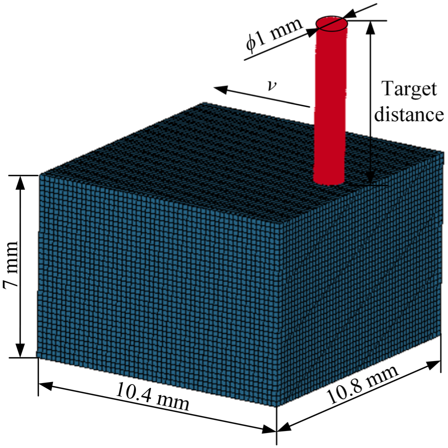
High-pressure water jet demolition model.
The “MAT_NULL” model in LS-DYNA, usually combining with the Gruneisen state equation, can be used to describe the water material.33,34 Thus, the material model for high-pressure water jet in the simulation adopted “MAT_NULL” model and its parameters are listed in Table 1. The rock material model in this study is set as the RHT (Riedel-Hiermaier-Thoma) model. RHT model can well describe the mechanical behavior of materials in the stage of impact compression and characterize the rock fragment performance under continuous water jet cutting better.35,36
Material model parameters of high-pressure water jet.

To illustrate the effectiveness, the rock model parameters were calibrated using uniaxial compression and Brazilian splitting experiments and the RHT model parameters were obtained after multiple comparison adjustments of the numerical simulation and experiment. The comparison results of equivalent stress versus loading displacement in numerical simulation and experiments are illustrated in Figure 4. We can figure out that the stress-displacement curves all show the law of increasing until the rock breaking strength reached and the maximum equivalent stress in numerical simulation is consistent with that in experiments. The above results demonstrate that the stress-displacement curves of rocks measured in both numerical simulation and experiments confirm to the fracture characteristics of rocks under these parameters. The parameters set for RHT model in high-pressure water jet demolition model were presented in Table 2.

Equivalent stress versus loading displacement: (a) uniaxial compressive strength and (b) Brazilian splitting.
Parameters of RHT model for rock.

Other setting in the numerical model are as follows. The contact model “Contact_Eroding_Nodes_To_ Surfac” were adopted. The failure criterion is set through “Mat_Add_Erosion.” When the rock failure criterion was met, the rock mass grid was categorized as a failure and automatically deleted. The high-pressure water jet velocity is set through “Define_ SPH_Injection” and the transverse velocity is set through “Boundary_Prescribed_Motion_Set.”
To verify the validity of the numerical model, the high-pressure water jet cutting experiments were conducted on the high-pressure water jet experiment platform, which mainly consists of the high-pressure water jet generation system, the motion control platform and the water jet nozzle, as shown in Figure 5. The maximum working pressure of the high-pressure water jet is 120 MPa, the nozzle diameter is 1 mm and the transverse velocity can be tuning from 1 to 5 m/min.

High pressure water jet experiment platform.
Given the cutting capacity of the high-pressure water jets, the water jet velocity is much greater than the transverse velocity. Amplifying the transverse velocity to study fragmentation under high-pressure water jets has been proved by the metallic material cutting under high-pressure water jets. 37 When the transverse velocity in the numerical simulation is approximately 600 times that of the experiment, the variation laws of the rock demolition depth under different the transverse velocity are consistent. 38 Apart from the transverse velocity, the other working condition parameters, such as the water jet velocity, the water jet diameter and the water jet target distance, are set consistently. Comparison shows that the relationship between the transverse velocity and the rock demolition depth of numerical simulation is consistent with that of experiment, as shown in Figure 6.

Relationship between demolition depth and transverse velocity.
To further verify that the correctness of the numerical model, the rock demolition performance in the simulation and experiment were compared under the condition that the working pressure is set as 40 MPa and the transverse velocity is set as 1.8 m/min. The rock demolition depths in the numerical simulation and experiments were 9.4 and 8.2 mm, the demolition widths were 2.0 and 1.7 mm, respectively. The errors of the rock demolition depth and width in the numerical simulation and experiment are 14.6% and 17.6%. The reasonable cutting errors and the calibration results of the rock mechanics properties prove that the developed numerical model can effectively simulate the process of high-pressure water jet cutting rock.
Demolition mechanism and performance analysis
Single continuous high-pressure water jet
Demolition mechanism analysis
The demolition crater evolution process under the cutting of continuous high-pressure water jet is shown in Figure 7. High-pressure water jet initially cut rocks with a small demolition area and the crater diameter is similar with that of the water jet. As the cutting continues, the diameter of high-pressure water jet is altered by rebound jet particles and some diffuse outwards, causing the demolition crater developing into bowl pits. Until the cutting completing, the demolition crater shape no longer changes.
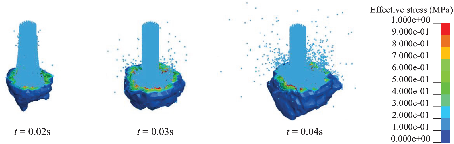
Evolution process of demolition crater.
To analyze the rock failure mechanism under high-pressure water jet and the cutting stress of the rock elements, the effective stress variation laws of the longitudinal and transverse rock elements were extracted. The longitudinal and transverse elements on the rock sample are arbitrarily selected, and location is illustrated in Figure 8. The effective stress variation laws of the longitudinal and transverse rock elements are demonstrated in Figure 9.

Position of effective stress extraction rock elements: (a) position of longitudinal rock elements and (b) position of lateral rock elements.

Variation laws of effective stress in rock elements: (a) effective stress variation of longitudinal elements and (b) effective stress variation of lateral elements.
Figure 9(a) shows that the effective stress is smaller in the initial cutting process and fluctuating upward with the high-pressure water jet traversing close to the selected elements. Once the water jet particles cut the selected rock elements, the effective stress accelerates to the peak. When the effective stress exceeds the rock failure stress, the rock elements fragmentate and the effective stress drops to zero instantaneously. Compared with the effective stress of cutting area edge elements, the effective stress of central elements has a low peak. This is because that the central elements are elastic deformation, while the edge elements are tensile failure. Figure 9(b) shows that the effective stress of the central elements quickly reaches its peak and fails instantaneously. The rock elements that far away from the center of water jet are repeatedly affected by cutting stress waves, resulting in the effective stress fluctuating. In addition, the failure rate of different rock elements varies but has the same instantaneous characteristics and the edge elements presenting higher peak values of failure stress.
Cutting performance analysis
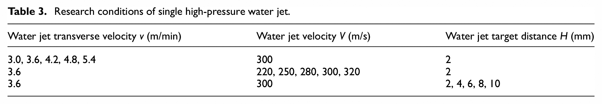
The target distance, water jet velocity and transverse velocity of high-pressure water jet have an important influence on the demolition performance. Therefore, reasonable working parameters can improve the demolition efficiency and reduce the investment cost. This section will explore the influence of water jet velocity, water jet transverse velocity, target distance on the demolition width and depth. The working conditions is shown in Table 3.
Research conditions of single high-pressure water jet.
The influence of transverse velocity on the demolition width and depth is shown in Figure 10, which shows that the demolition width remains stable with transverse velocity and varies at 1.6 mm. The demolition depth decreases with transverse velocity and tends to be stable eventually. The change of demolition depth is more remarkable when the transverse velocity changes from 3.0 to 4.2 m/min compared to 4.2 to 5.4 m/min. As the transverse velocity increases, the time for the high-pressure water jet to cut the same rock elements will be shortened, causing the upper rock element failed and the lower rock element preserved with the shallow demolition depth.

Variation of width and depth of demolition with water transverse velocity.
The influence of water jet velocity on the demolition width and depth is shown in Figure 11, which illustrates that the demolition width decreases and gradually stabilizes with the water jet velocity, while the demolition depth shows a non-linear increasing trend. In the low velocity stage, the instantaneous cutting stress of high-pressure water jet on the rock surface does not reach the failure stress and the water jet particles diffuse outward under the subsequent particles compression. The rock element effective stress accumulates to the failure stress under continuous cutting, resulting in rock element fragmented with a large demolition width. But the demolition depth is still shallow attributing to the short cutting time. With water jet velocity increasing, the demolition depth increases rapidly, which is generated by water hammer phenomenon.

Variation of demolition width and depth with water jet velocity.
The influence of water jet target distance on the demolition width and depth is shown in Figure 12, which demonstrates that the demolition width and depth are stable when the water jet target distance changes from 2 to 10 mm. This is because that the cutting capability of water jet particles is weakened by collision between the water jet particles. During the actual cutting process, the cutting energy of high-pressure water jet undergoes resistance loss. However, the influence of water jet target distance in the millimeter level on resistance loss is much smaller than that of the water jet velocity under hundred meters per second condition.

Variation of demolition width and depth with water target distance.
Cutting performance analysis of high-pressure abrasive water jet
To further validate the superiority of the established model, it was extended for the investigation of abrasive water jet. The established model is presented in Figure 13 and the dimensions is identical to those in Figure 2. The abrasive water jet comprises abrasive particles and water jet particles. The abrasive mass percentage in abrasive water jet can be changed by adding different number of abrasive particles. The abrasive mass percentages configured for the abrasive water jet in this study were 1%, 2.5%, 4%, 5.5% and 7%.

Abrasive water jet demolition model.
The influence of abrasive mass percentages on the demolition width and depth is shown in Figure 14. We can figure out that the demolition width and depth of abrasive water jet are significantly increased compared with high-pressure water jet without abrasive. The demolition width is fluctuating with the abrasive mass percentages, while the demolition depth first increases and then tends to be stable. Within the mass percentage range in this study, the maximum increase of the demolition width and depth of water jet is around 50% under the impact of abrasive. Generally, higher abrasive mass percentages in the abrasive water jet leads to a greater impact energy. However, the probability of collision between abrasive particles will be exacerbated with the abrasive mass percentage increase. The collision between abrasive particles will diminish the impact energy and the demolition performance of high-pressure water jet cannot be improved further.

Variation of demolition width and depth under different abrasive mass percentages.
Multiple continuous high-pressure water jets
Demolition mechanism analysis
Due to the similarity, this paper takes rock cutting by double water jets as the research object and its modeling is the same as the section “Demolition modelling” presented. The demolition crater evolution process of the rock cutting under the double high-pressure water jet is shown in Figure 15.

Evolution process of demolition crater under double high-pressure water jet.
High-pressure water jets initially cut rocks with a huge pressure that far exceeding the failure stress and a double water jet shaped demolition crater is formed on the surface. Compared with the single high-pressure water jet cutting process, the double high-pressure water jets cutting process has a remarkable diffuse phenomenon and a larger demolition range. And the center area under double high-pressure water jets cutting bears higher cutting stress. Furthermore, the effective stress variation laws of double high-pressure water jets are basically consistent with that of single high-pressure water jet.
Demolition performance analysis
The water jet spacing is another important parameter that affects the demolition performance and reasonable water jet spacing can improve the work efficiency. Since the influence of water jet velocity and transverse velocity on the high-pressure demolition performance under double high-pressure water jets is similar with that of single high-pressure water jet, this section only explores the effect of water jet spacing on demolition performance. The working conditions are shown in Table 4.
Working conditions of multiple high-pressure water jets.

The variations of the demolition width and depth under different water jet spacing are presented in Figure 16. We can figure out that the demolition width of the double water jets increasing firstly and then decreasing with water jet spacing. The demolition width keeps increasing until the water jet spacing reaching 2.2 mm, where the demolition width reaches its maximum. This is because that the force from the double water jets is exerted into the rock elements at the water jet spacing, leading to the increase in demolition width. When the spacing increases to a certain extent, the force is insufficient to fracture the rock. The remarkable increase in demolition width only occurs while the water jet spacing is under an appropriate working condition. Figure 16(b) shows that the demolition depth decreases firstly and then tends to be stable with the water jet spacing. The demolition depth of the multiple high-pressure water jets is much deeper than that of the single water jet under the small water jet spacing condition. This is because that the cutting force is significantly increased attributing to the overlap of high-pressure water jets.

Variation of demolition width and depth with water jet spacing: (a) width variation and (b) depth variation.
Variation of the demolition area with water jet spacing is shown in Figure 17. The curve of demolition area varies sinusoidally with jet spacing and there are two extreme points. The first extreme point is 1 mm, where the demolition area reaches its maximum value of 20.16 mm2, while the demolition width is only 2.8 times the water jet diameter. The second extreme point is 2.2 mm and the value of demolition area is 17.64 mm2, which is smaller than the first extreme point. Compared with the first extreme point, the demolition width has increased 1.5 times.

Variation of cross-sectional demolition area with water jet spacing.
Rock demolition crater under different water jet spacing at 0.18 s is shown in Figure 18. The demolition crater at the first extreme region is narrow and deep, while the demolition crater at the second extreme region is wide and shallow. The cutting bulge occurs when the water jet spacing is 2.2 times the water jet diameter. This incomplete fragmentation phenomenon illustrates that the double high-pressure water jets reached the limitation of the cutting width when the water jet spacing exceeds 2.2 times the water jet diameter. Since the demolition depth can be increased by reducing the transverse velocity to prolong the cutting time, setting the water jet spacing around 2.2 times the water jet diameter is more reasonable for multiple high-pressure water jets.

Rock demolition cloud maps with water jet spacing at 0.18 s.
Conclusion
The developed demolition model based on SPH coupling with FEM can realize the continuous water jet only by a single layer of SPH particles rather than multi-layer SPH particles superposition, which saves lots of calculation cost and can achieve the unrestricted long-time continuous water jet. Under the continuous water jet cutting, the failure rate of the different rock elements shows an instantaneous damage phenomenon. The maximum damage stress of the central rock elements is smaller than that of the edge.
The demolition width remains stable with transverse velocity and target distance, while decreases with water jet velocity and gradually stabilizes. The demolition depth remains unchanged with different target distance, while decreases with transverse velocity and tends to be stable eventually, as well as showing a nonlinear increasing trend with the water jet velocity. Moreover, the demolition width and depth increase with abrasive mass percentage, but the aggravated collision between abrasive particles of high mass percentage will prevent the values increase. Comparative study shows that the demolition width is more sensitive to the water jet velocity, and the demolition depth is more sensitive to the transverse velocity and the water jet velocity.
Under the cutting of multiple high-pressure water jets with different water jet spacing, the rock demolition width increases firstly and then decreases, the demolition depth shows decreasing exponential law, and the demolition crater cross-section area shows a sinusoidal variation law. The incomplete fragmentation phenomenon occurs when the water jet spacing is 2.2 times the water jet diameter. Setting the water jet spacing around 2.2 times the water jet diameter is more reasonable for multiple high-pressure water jets applied in demolition robot.
Footnotes
Correction (December 2025):
Article has been updated to correct figures 2, 3, 4, 5, and 15.
Handling Editor: Sharmili Pandian
Funding
The author(s) disclosed receipt of the following financial support for the research, authorship, and/or publication of this article: This work is supported by the Suzhou Science and Technology Plan (Basic Research) Project (SJC2023002), the Basic Science (Natural Science) Research Project of Higher Education Institutions in Jiangsu Province (23KJB440002), the Suzhou Science and Technology Plan (Key Technology Research and Development) Project (SYG2024071).
Declaration of conflicting interests
The author(s) declared no potential conflicts of interest with respect to the research, authorship, and/or publication of this article.