
Abstract
High entropy alloys exhibit superior mechanical properties, especially wear resistance, making them crucial for wear-resistant and surface protection applications, necessitating in-depth research into their wear resistance and coating materials. This study utilizes molecular dynamics methods to perform a comprehensive investigation and meticulous analysis of the wear resistance of FeNiCrCoAl high entropy alloys, with the goal of providing crucial theoretical support for their practical applications. The FeNiCrCoAl high entropy alloy was applied as a coating onto an Al substrate, serving as the subject of friction simulations. By regulating the indentation depth of abrasive particles and coating thickness, we systematically examined how these factors affect the friction properties of the material. The findings reveal that when the depth of abrasive pressing is less than the coating thickness, the friction coefficient rises with increasing pressing depth; conversely, when the pressing depth exceeds the coating thickness, the friction coefficient decreases. As the coating thickness increases, the material generates a reduced proportion of disordered lattice structures during friction, accompanied by an increase in dislocation line density. This suggests a reduced wear from abrasive particles, indicating that thicker coatings enhance the material’s wear resistance.
Introduction
High wear and friction have been significant problems for engineering since material loss leads to significant component failure, friction losses, and large economic costs. Therefore, scientists have been eager to discover new wear-resistant materials. In the last few decades, high entropy alloys (HEAs) have become a research hotspots in recent years due to their unique physical and chemical properties such as high temperature stability, high hardness, high strength, high corrosion resistance creep resistance, wear resistance, low friction, high toughness, and good ductility.1–3 In particular, HEAs appears to be highly promising and economically viable to apply HEAs as coating materials to provide contact and wear protection for mobile mechanical devices and lengthen their service life based on these excellent corrosion and wear resistance advantages. 4 HEA coatings have been developed at high-temperature applications in automobile sector, turbine and aerospace applications to improve the durability of base alloy components in various gaseous and corrosive atmospheres. 5 In practical applications, the tribological properties of HEA coatings are one of the key factors for affecting the durability and performance of coatings under extreme conditions such as high temperature, high pressure, and high speed.
Previous experiment works have shown that HEA coatings have an outstanding wear resistance.6–9 Among these alloys, FeNiCrCoAl HEA is considered as an ideal coating structural material due to its excellent thermal stability, high-temperature oxidation resistance, and excellent mechanical properties. 10 Molecular dynamics models were built to explore the influences of scratching velocities on wear behavior of FeNiCrCoAl HEA coating on Ni substrate during scratching. 11 However, few literatures have been reported on the wear behavior of FeNiCrCoAl high-entropy alloy coatings from the micro mechanism level.
Therefore, this paper aims to systematically investigate the tribological properties of FeNiCrCoAl HEA coatings in order to provide a theoretical and experimental basis for their application under extreme operating conditions such as high temperature, high pressure, and high velocity. Specifically, this article will use molecular dynamics to conduct friction simulation and analysis using LAMMPS software, to investigate the tribological properties of adding FeNiCrCoAl HEA coatings to the Al matrix and analyze and interpret the tribological behaviors and mechanisms of these coatings. The purpose of adding different thickness of high entropy alloy coating on the soft Al substrate is to compare the friction resistance of different thickness of high entropy alloy coating. Furthermore, it offers a theoretical foundation for discussing the enhancement mechanism of friction properties when high-entropy alloys are added to the surfaces of other softer metallic materials. At the same time, this article will also explore how to find suitable coating thicknesses for different use scenarios in different environments.
Simulation model and method
In this study, the LAMMPS molecular dynamics software was used for modeling and simulation, and OVITO software was used as a visualization software for processing results. Taking single crystal Al as the substrate and FeNiCrCoAl HEA as the coating material, the lattice types of both materials were set as face-centered cubic (FCC). The lattice constant of Al is a = 4.05 Å, and the lattice constant of FeNiCrCoAl HEA is b = 3.56 Å. The model size of the Al substrate was 145 Å × 217 Å × 58 Å, with a total of 112,752 atoms. The HEA coating corresponds to four coating thicknesses (CT) with different cuttings of depths (COD), which are 10, 14, 18, and 22 Å. The substrate and coating adopt the same crystal orientation, with the x-axis, y-axis, and z-axis corresponding to the [100], [010], and [001] directions, respectively. We treat the high-entropy alloy coating and the substrate as a unified entity, ensuring that their lattice structures remain continuous. The periodic boundary conditions were adopted for x and y axis, and shrink-wrapped boundary conditions were adopted for z axis. The model was divided into the rigid, thermostat, and free zones, as shown in Figure 1(a).

(a) Schematic diagram of friction model and (b) atomic distribution of different elements.
The embedded atom method (EAM) was used for the interaction between the five atoms of FeNiCrCoAl HEA. 12 The EAM potential function is a model used to describe the interactions between atoms in multi-atom systems, which is mainly used in the study of alloys and can capture the complexity of atomic interactions in metals, including the embedding effect of electrons, as shown in equation (1).

where UEAM is the total energy, rij is distance between the atom i and j,
The Tersoff potential function was originally proposed by John Tersoff in 198813,14 and is used to simulate the interaction between atoms in silicon materials. The Tersoff potential function is an empirical potential function that describes the interaction between non-metallic elements and is particularly suitable for describing materials containing carbon and silicon. The form of the Tersoff potential function is relatively complex, but it can be basically divided into two parts: a pair interaction term and a three-body interaction term. The pair interaction term describes the interaction between two neighboring atoms, while the three-body interaction term considers the interaction between three neighboring atoms. The pairwise interaction potential energy is usually represented by the following expression:

where rij is the distance between the i-th atom and the j-th atom; fc(rij) is a truncation function, which is used to truncate interactions within a certain distance range; VR(rij) is an attractive term, which describes the attraction between atoms, while βijVA(rij) is a repulsive term, which describes the repulsion between atoms; βij is a parameter that adjusts the relative strength between attraction and repulsion. The three-body interaction term is used to describe the interaction between three neighboring atoms, and its expression is as follows:

Among them, ηijk is a characteristic quantity related to the atomic triplet configuration. This term is mainly used to correct the pair interaction, making the Tersoff potential function better able to describe the properties of materials.
During the friction process, the interaction between the abrasive diamond particle and the metal atoms is simulated using the Lennard-Jones potential function.15,16 The form of the force acting on the system is as follows:

In this context, r denotes the distance between two particles, σ is the cut-off distance of the potential energy function, and ε is the depth of the potential energy function, commonly referred to as the LJ parameter. The LJ potential energy function consists of two terms. The first term is an attractive term, representing the van der Waals attraction between atoms, while the second term is a repulsive term, indicating the van der Waals repulsion between atoms. These two terms together determine the total energy of the interatomic interaction. The LJ force field is a non-covalent force field used to describe the interactions of non-covalent bonds (such as van der Waals forces and electrostatic interactions) in molecules. The parameters of the LJ force field can be obtained through experiments or calculations and are adjusted and optimized based on the simulated system. The values of σ and ε for different elements are shown in Table 1.
L-J parameters for interactions between different atom pairs.

After the model construction was completed, in order to optimize the atomic structure of the model, the conjugate gradient algorithm 20 was first used to minimize the energy of the model. The conjugate gradient method is based on iteratively solving linear equations using a series of conjugate directions. In each iteration, the information from the previous calculation is used to accelerate the calculation. Specifically, in solving Ax = b, the conjugate gradient method calculates the residual r = b−Ax and a series of conjugate directions p and uses this information to iteratively calculate the final solution. The conjugate gradient method has the advantages of low iteration times and fast convergence and is widely used in solving large-scale linear equations and optimization problems. In order to achieve a balanced state for the model, the temperature was initialized first, with an initial temperature of 300 K. The following four steps were performed using the Nosé-Hoover heat bath method. 21 In the first step, the model was heated from 300 to 1000 K using the NPT ensemble,22,23 taking 200 ps; in the second step, the model was maintained at 1000 K for 100 ps using the NVT ensemble 23 ; in the third step, the temperature was lowered from 1000 to 300 K using the NPT ensemble, taking 200 ps; in the fourth step, the model was maintained at 300 K for 100 ps using the NVT ensemble. The model reached a balanced state, and the atomic distribution is shown in Figure 1(b).
The initial position of the abrasive particles was above the matrix. Initially, the abrasive particles are pressed into the matrix at a speed of 10 m/s in the negative Z direction. Upon reaching the predetermined depth, they are then rubbed along the positive Y direction at a speed of 100 m/s. Throughout the entire process, the Al layer and the HEA layer are configured as NVE ensembles, while the constant temperature layer was set to NVT ensemble, maintaining a temperature of 300 K.
Results and discussion
The influence of different pressing depths on tribological properties
Figure 2 shows the variation of normal forces with pressing depths under five different coating thicknesses. The positive force continuously increases as the thickness of the FeNiCrCoAl HEA coating increases, with an abrasive penetration depth of 8 Å. The positive force increases continuously with the increase of the thickness of the FeNiCrCoAl HEA coating. When the coating thickness is 10 Å, the increase in amplitude significantly decreases. When the indentation depth of the abrasive particles is 12 Å, the positive force increases continuously with the increase of the thickness of the FeNiCrCoAl HEA coating. When the coating thickness reaches 14 Å, the increase amplitude significantly decreases, and before 14 Å, the increase amplitude is larger. When the indentation depth of the abrasive particles is 16 Å, the positive force increases continuously with the increase of the thickness of the FeNiCrCoAl HEA coating to 18 Å. When the coating thickness reaches 22 Å, the increase amplitude significantly decreases.
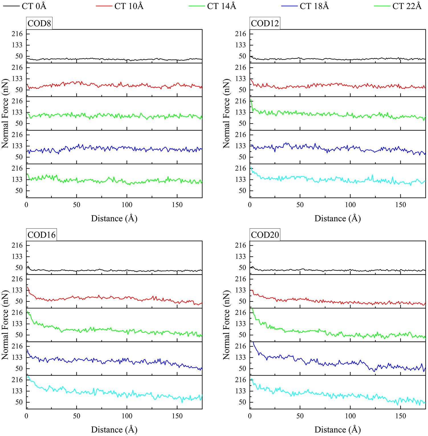
Normal force exerted by abrasive particles under five different coating thicknesses.
The variation in tangential force is illustrated in Figure 3. At an abrasive penetration depth of 8 Å, the tangential force escalates as the thickness of the FeNiCrCoAl HEA coating increases. However, once the coating thickness attains 10 Å, the rate of increase noticeably diminishes. Similarly, when the abrasive penetration depth increases to 12 Å, the tangential force continues to rise with the increasing thickness of the FeNiCrCoAl HEA coating. However, after reaching a coating thickness of 14 Å, the rate of increase slows down, with a steeper increase observed before 14 Å. Furthermore, at an abrasive penetration depth of 16 Å, the tangential force experiences a noticeable decrease in increase after the coating thickness reaches 18 Å, with a steeper increase observed before 18 Å. Lastly, when the abrasive penetration depth is 20 Å, the tangential force exhibits a significant increase as the thickness of the FeNiCrCoAl HEA coating increases to 22 Å.

Tangential force of abrasive particles across five different coating thicknesses.
As the coating thickness increases, both the normal force and tangential force continuously rise. When the coating thickness is less than the indentation depth, the normal and tangential forces undergo significant changes with the increase in coating depth. However, once the coating thickness exceeds the indentation depth, the magnitude of these changes diminishes.
As shown in Figure 4(a), the overall trend remains consistent across the four indentation depths. Specifically, the friction coefficient is minimal when the coating thickness is 0 Å, and then begins to rise as the thickness increases, gradually stabilizing thereafter. From the maximum values observed at the four indentation depths in the graph, it can be inferred that when the indentation depth is less than the coating thickness, the friction coefficient increases with increasing indentation depth. Conversely, when the indentation depth exceeds the coating thickness, the friction coefficient experiences a slight decrease, subsequently stabilizing. Figure 4(b) illustrates the wear of the substrate at four different indentation depths. At the same indentation depth, the number of wear atoms initially increases and then decreases as the coating thickness increases. The maximum value is achieved when the coating thickness is 10 Å.

Coefficient of friction and wear atom numbers of five coating thicknesses of abrasive particles at four indentation depths: (a) Friction coefficient varies with coating thickness and (b) The number of worn atoms varies with the thickness of the coating.
To investigate the micro-deformation mechanism of a FeNiCrCoAl high-entropy alloy (HEA) coating (14 Å thickness) under friction, we analyzed dynamic lattice changes using Common Neighbor Analysis (CNA). Figure 5 illustrates the structural evolution during abrasive particle movement (left to right) at varying indentation depths. As the diamond abrasive’s indentation depth increased from 8 to 20 Å, the face-centered cubic (FCC) structure proportion decreased from 73% to 64%, indicating reduced crystallographic order. Amorphous/defective structures increased from 25% to 33%, suggesting friction-induced atomic disordering. HCP Phase Formation: Hexagonal close-packed (HCP) structures emerged at grain boundaries, rising from 1.4% to 3.7%, correlating with deeper indentation. Increased grain boundary density due to localized plastic deformation. Stress concentration at grain boundaries triggered FCC-to-HCP transitions, with HCP proportion scaling with indentation depth. Progressive loss of FCC order and accumulation of disordered/defect phases. The observed trends FCC decline, disordered phase growth, and HCP nucleation highlight a friction-driven microstructural reconfiguration. These changes imply that higher indentation depths exacerbate lattice distortion, promoting defect generation and phase transformation. The HCP phase at grain boundaries may act as a stress buffer but could also accelerate crack initiation under cyclic loading. This mechanism underscores the interplay between mechanical stress and crystallographic evolution in HEAs, providing insights for designing wear-resistant coatings.

From a top-down perspective, the lattice structure changes with a coating thickness of 14 Å at pressing depths of 8 Å (a), 12 Å (b), 16 Å (c), and 20 Å (d), and friction distances of 0 Å (1), 90 Å (2), and 175 Å (3), respectively.
The transition from ordered structure to disorder during friction has also been observed in other high-entropy alloy experiments, including those conducted by Wu et al., who discovered the phase transformation behavior of FeNiCrCoMn high-entropy alloy. 24 Kelchner et al. argue that stress can induce phase transition behavior in high-entropy alloys, 25 whereas Korchuganov and his team maintain that the phase transition in these alloys is primarily attributed to the elevation of atomic potential energy. 26 During the lattice transformation, stacking faults continue to accumulate, forming a 45° angle with the normal indentation. This may be attributed to the damage inflicted on the matrix by the pressure exerted by the indenter, resulting in stress exceeding the critical nucleation stress required for the formation of stacking faults. This phenomenon has also been observed in other alloy systems.27,28 By observing the changes in lattice structure, it can be discerned that as the indentation depth increases, the wear of the material also exhibits a continuous rise, which aligns with the tangential force encountered during the loading process. Once the indentation depth of abrasive particles surpasses the coating thickness, as depicted in Figure 5(c) and (d), the Al matrix material becomes exposed, and the normal force diminishes during the loading phase. Consequently, the material exhibits superior friction resistance when the indentation depth of abrasive particles remains below the coating thickness.
According to the dislocation theory, the movement of all dislocations typically follows the path of lowest energy. Whether dislocations interact with each other primarily hinges on two conditions. That is, the geometric condition requires the conservation of the Burgers vector to be satisfied, while the energy condition stipulates that the reaction of dislocation must be accompanied by a reduction in energy. The diamond indenter generates significant stress in the matrix material. During the friction process, if the continuously accumulating stress exceeds the critical resolved shear stress value, the matrix material will relieve the stress through the nucleation and slippage of dislocations. 29 The type and length of dislocations are determined through the dislocation extraction algorithm (DXA). 30 Figure 6 illustrates the evolution of dislocations during the friction process. The red arrow designates the friction position of the abrasive grains, which initiate rubbing from left to right. As the abrasive grains interact with the substrate surface, dislocations nucleate beneath the indenter. With increasing penetration depth, these dislocations propagate through the matrix along the depth direction, facilitating stress release. In group a, the indentation depth is 8 Å. Notably, the length of Shockley incomplete dislocations expands from an initial 185.45 to 885.74 Å, while the length of perfect dislocations decreases from 656.14 to 193.14 Å. Additionally, the length of stair-rod incomplete dislocations decreases from 29.49 to 16.78 Å. The number of Hirth incomplete dislocations increases from 0 to 26.65 Å, and the number of Frank incomplete dislocations rises from 0 to 19.06 Å. These observations underscore the profound impact of the friction process on the dislocation structure within the matrix material. Different types of dislocations exhibit distinct evolution patterns under the influence of friction stress.

The dislocation evolution with a coating thickness of 14 Å under various indentation depths of 8 Å (a), 12 Å (b), 16 Å(c), and 20 Å (d), as well as friction distances of 0 Å (1), 90 Å (2), and 175 Å (3), observed from a front view perspective.
In the FCC lattice structure, all dislocations exist in an unstable state and spontaneously decompose into Shockley incomplete dislocations via the reaction mechanism. Consequently, Shockley incomplete dislocations predominate in the nucleation process, with Hirth incomplete dislocations, Stair-rod incomplete dislocations, and Frank incomplete dislocations nucleating subsequently through interactions with Shockley incomplete dislocations. Throughout the entire dislocation reaction process, Shockley incomplete dislocations maintain their dominant position. During the friction process, the number of Shockley incomplete dislocations continues to increase, while the population of all dislocations decreases significantly as they are destroyed and further decomposed into Shockley incomplete dislocations. The limited presence of Stair-rod incomplete dislocations and Hirth incomplete dislocations is attributed to their formation mechanism, which involves connecting different Shockley incomplete dislocations through stacking faults on distinct planes, rendering their formation less favorable. Frank incomplete dislocations, on the other hand, are synthesized through dislocation reactions associated with Shockley incomplete dislocations, explaining their scarcity. The slippage of Shockley incomplete dislocations plays a pivotal role in material deformation, aligning with observations made in previous experiments.31–33 As the indentation depth increases, the linear density of dislocations also rises. This enhanced dislocation density, coupled with their obstructive effect, leads to a corresponding increase in tangential force during the friction process, ultimately enhancing the material’s friction properties.
The impact of varying coating thicknesses at the same indentation depth
When the indentation depth of abrasive particles is 12 Å, nine coating thicknesses, namely 0, 10, 14, 18, 22, 30, 42, 50, and 70 Å, were selected. The tribological properties were analyzed at the same indentation depth. As shown in Figure 7, when the thickness of the HEA coating increases from 0 to 10 Å, both the normal force and tangential force increase significantly, with the tangential force increasing by four times and the normal force increasing by two times. As the coating thickness continues to increase, both the normal force and tangential force increase, albeit at a decreasing rate. When the coating thickness reaches 42 Å, further increases in coating thickness result in minimal changes in both the normal and tangential forces, which remain essentially unchanged.
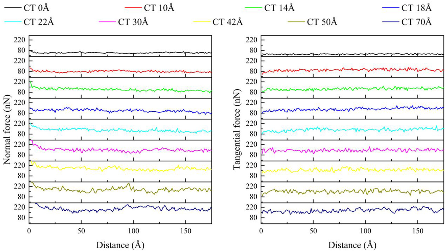
Normal force and tangential force of abrasive particles with varying coating thicknesses at an indentation depth of 12 Å.
To investigate the impact of coating thickness (10, 22, 50 Å) on lattice evolution in FeNiCrCoAl high-entropy alloys during friction, we analyzed structural changes via top-down observations (Figure 8). Thicker coatings showed higher initial FCC order from 68.5% (10 Å) to 83.4% (50 Å), while disordered phases decreased from 29.9% (10 Å) to 13.7% (50 Å). Reduction: All coatings exhibited FCC decline (10 Å: 68.5%→64%; 22 Å: 80.2%→71%; 50 Å: 83.4%→ 80%). Disorder increased proportionally to coating thinness (10 Å: 29.9%→34.3%; 22 Å: 18.1%→25.5%; 50 Å: 13.7%→16.6%). HCP Formation: Grain-boundary HCP phases grew with thickness—10 Å (1.6%→ 1.7%), 22 Å (1.7%→3.6%), 50 Å (2.9%→3.4%). Thicker coatings resisted FCC degradation due to higher initial crystallinity, while thinner coatings accelerated disorder generation. HCP accumulation at grain boundaries correlated with coating thickness, suggesting stress buffering but potential brittleness risks. Coating thickness critically governs lattice stability: thicker coatings preserve FCC order, reduce disorder, and promote HCP formation at boundaries during friction. This highlights the role of structural hierarchy in tailoring wear-resistant HEA coatings.

From a top-down perspective, when the pressing depth is 12 Å, the coating thicknesses are 10 Å (a), 22 Å (b), and 50 Å (c), respectively. The corresponding friction distances are 0 Å (1), 90 Å (2), and 175 Å (3), respectively.
During the initial stage, the insertion of diamond abrasive particles into the matrix generated significant stress, exceeding the critical nucleation stress threshold for stacking faults. Consequently, stacking faults emerged throughout the friction process, forming a 45° angle with the normal indentation. This surface defect resulted in the transformation of the lattice structure from FCC to a minor amount of HCP. The substantial stress triggered phase transformation behavior in the high entropy alloy. Furthermore, during the friction process, the stacking faults continued to proliferate. As the coating thickness increased, the proportion of ordered lattice structures at the end of friction progressively rose, indicating enhanced elastic properties and improved deformation recovery capabilities. 34 Consequently, the wear resistance of the material exhibited sustained enhancement.
To explore the impact of coating thickness on the friction-induced microstructure of FeNiCrCoAl high-entropy alloys, a comparison of lattice evolution was conducted across three thicknesses: 10, 22, and 50 Å (Figure 9). The results revealed that as the thickness increased from 10 to 50 Å, the initial proportion of the FCC phase rose from 68.5% to 83.4%, while the disordered phase decreased from 29.9% to 13.7%, suggesting that thicker coatings exhibit a higher degree of crystalline order. During the friction process, all coatings exhibited a decline in the FCC phase (with decreases of 4.5% for 10 Å, 9.2% for 22 Å, and 3.4% for 50 Å) and an increase in the disordered phase (with increases of 4.4% for 10 Å, 7.4% for 22 Å, and 2.9% for 50 Å). Additionally, there was a notable increase in the grain boundary HCP phase with increasing thickness (from 1.6% to 1.7% for 10 Å, from 1.7% to 3.6% for 22 Å, and from 2.9% to 3.4% for 50 Å). Mechanism analysis indicates that thick coatings, such as 50 Å, possess stronger FCC stability during friction due to their high initial order, whereas thin coatings, like 10 Å, have a high density of defects that accelerate disorder. The thickness-dependence of the HCP phase reflects an enhanced stress-buffering capacity in thick coatings, albeit potentially accompanied by the risk of grain boundary brittleness. In summary, coating thickness plays a pivotal role in governing the initial structural order and dictating the friction-induced lattice phase transformation pathway, offering crucial design insights for optimizing the wear resistance of high-entropy alloys.

The dislocation evolution is observed at an indentation depth of 12 Å with coating thicknesses of 10 Å (a), 22 Å (b), and 50 Å (c), and friction distances of 0 Å (1), 90 Å (2), and 175 Å (3) in the front view.
During the friction process, the number of various dislocations in the model with 10 coating thickness consistently decreased. This could be attributed to the fact that the indenter’s penetration depth exceeded the coating thickness of the high entropy alloy. Consequently, the deformation capabilities enhanced by dislocations were insufficient to cope with the level of damage. The material suffered permanent damage due to the abrasive particle friction, leading to a transition from an ordered lattice structure to a disordered one. As a result, all types of dislocation lines began to diminish. When the indenter penetration depth was less than the coating thickness, specifically for coating thicknesses of 22 and 50 Å, the total dislocations were resolved into Shockley incomplete dislocations during the friction process. The significant increase in Shockley incomplete dislocations subsequently led to an elevation in the dislocation lines of stair-rod, Hirth, and Frank incomplete dislocations. The dislocation line variations for the three coating thicknesses depicted in Figure 10 align with our anticipated outcomes. When the indentation depth of the indenter is less than the coating thickness, both the total dislocation count and line length decrease, whereas the number and length of Shockley incomplete dislocations increase, mirroring our findings in models with coating thicknesses of 22 and 50 Å. As the coating thickness increases, dislocation lines persistently grow, correlating with changes in the ordered proportion of the lattice structure. As evident from Figure 7, the material’s positive force increases concurrently, indicating that the relative alterations in lattice structure and dislocations collectively bolster the material’s friction properties.

Models with coating thicknesses of 10, 14, and 18 Å, and the changes in the number (a) of total dislocations and Shockley incomplete dislocations, as well as the length (b) of dislocation lines, during the friction process.
It can be observed from Figure 11 that the friction coefficient increases by 2.2 times after the addition of a 10 Å high entropy alloy coating. Subsequently, it exhibits a decreasing trend with increasing coating thickness, stabilizing at 0.9 from the material with a coating thickness of 50 Å. The trend in the number of worn atoms varies with coating thickness aligns with the change in friction coefficient. As the coating thickness increases, the material’s recovery ability improves. The metal bond strength between atoms in the high entropy alloy is significantly stronger than that of pure Al material. Consequently, when the metal bond is disrupted, the increase in tangential force exceeds that of the normal force, as illustrated in Figure 7, load-displacement curve, leading to an increase in the friction coefficient.

The friction coefficient and the number of wear atoms in high entropy alloy coating materials vary with the coating thickness.
The friction coefficient is calculated using the Amontons-Coulomb friction law,35,36 without considering the roughness of the friction surface. It is possible that the uneven surface of the material has contributed to a significant error, as illustrated in Figure 11. The error is smaller when the coating thickness is greater and when dealing with elemental Al, and the surface roughness changes during the indenter friction process are less pronounced. The friction coefficient variation pattern observed in this study aligns closely with the trend exhibited by the corresponding experimental results.37,38
Conclusion
This article employs molecular dynamics methods to conduct an in-depth analysis and investigation of the tribological properties of FeNiCrCoAl high entropy alloys at the atomic scale. Friction scratch simulations are utilized to analyze the evolution of lattice and dislocation behavior, while the friction coefficient of the material is calculated based on the Amontons-Coulomb friction law. The following conclusions were drawn regarding the tribological properties of two materials.
As the depth of abrasive grain indentation increases, the proportion of disordered lattice structure rises, accompanied by an increase in dislocation line density primarily due to Shockley incomplete dislocations. Through analysis of the lattice distortion effects in high entropy alloys, it is evident that the energy required by abrasive particles during this process also increases significantly, leading to an elevated friction coefficient and increased wear of the material. When the depth of abrasive pressing is less than the thickness of the coating, the friction coefficient increases with increasing pressing depth; however, when the pressing depth exceeds the coating thickness, the friction coefficient decreases as the pressing depth increases. As the coating thickness increases, the proportion of disordered lattice structures generated by the material during friction decreases, accompanied by an increase in dislocation line density. This suggests a reduction in the wear caused by abrasive particles on the material, indicating that as the coating thickness increases, the material’s wear resistance improves. After applying a high entropy alloy coating to the substrate material, there is a significant enhancement in the material’s tribological performance. For instance, when the thickness of the high entropy alloy coating is 7 Å, compared to the Al substrate material, the hardness increases by twice and the elastic modulus increases by 1.5 times.
Footnotes
Handling Editor: Sharmili Pandian
Funding
The author(s) disclosed receipt of the following financial support for the research, authorship, and/or publication of this article: This work was supported by the National Natural Science Foundation of China under Grant no. 12002223, the Natural Science Foundation of Hebei Province under Grant no. A2020210035 and E2022210032, the Scientific Research Plan Projects for Higher Schools in Hebei Province (Projects for young top talent) under Grant no. BJ2025102.
Declaration of conflicting interests
The author(s) declared no potential conflicts of interest with respect to the research, authorship, and/or publication of this article.