
Abstract
Aircraft continuously change their flight attitudes during actual operations. If a constant attitude is maintained during wind tunnel tests, the aerodynamic characteristics obtained may significantly deviate from the actual performance of the aircraft. Such discrepancies hinder the optimal design of aircraft and can adversely affect safety. The dual-rotating shaft mechanism is a commonly used model support system in wind tunnel testing, playing a crucial role in simulating various flight attitudes of the aircraft. The paper integrates the structural characteristics of a newly designed dual rotating shaft mechanism to perform a numerical analysis of its aerodynamic shape and evaluate its impact on the quality of the wind tunnel flow field. Multiple rounds of numerical simulations and comparative analyses were carried out on mechanisms with different structural configurations, leading to an optimized structural design. Subsequently, corresponding experiments were conducted to validate the design results. The results indicate that reducing the axial width and thickness of the front shaft crutch arm and positioning it further from the rotor center can alleviate upstream interference. The research provides a valuable reference for the future development of dual rotating shaft mechanisms.
Keywords
Introduction
The shape of an aircraft is closely related to its aerodynamic characteristics, and wind tunnel testing is a key step in evaluating the aircraft’s shape and obtaining data for optimization design. The quality of the wind tunnel flow field directly affects the authenticity of the test results.1–5 Since aircraft continuously adjust their flight attitudes during actual operation,6–10 conducting wind tunnel tests with a constant attitude can lead to very limited flight attitude envelope data, which may introduce potential flaws in the design and safety of the aircraft.11,12 Therefore, during wind tunnel testing, the model must simulate various flight attitudes based on flight conditions to obtain complete and authentic data for verification and design guidance. The ability to simulate changes in flight attitude relies on the wind tunnel model support mechanism. The wind tunnel model support mechanism should meet the requirements for adjusting the attitudes of the aircraft model during testing. However, while the model support mechanism changes the aircraft’s attitude, its main structure can interfere with and affect the wind tunnel flow field. Consequently, designing a support mechanism that meets the needs of wind tunnel testing while minimizing interference with the flow field has become an important issue that urgently needs to be addressed in wind tunnel experiments. 13
The dual-axis support mechanism 14 is commonly used in wind tunnel tests to simulate various flight attitudes. It consists of two rotation shaft mechanisms powered by high-frequency response motors, which are combined in series. During wind tunnel testing, the test model is connected to the dual-axis mechanism via support rods and is placed within the flow field. Throughout the test, the model’s attitude is changed by the rotation of the two shafts of the dual-axis mechanism about their own axes, as illustrated in Figure 1. The dual rotary axis mechanism is a support mechanism commonly used in wind tunnel testing to simulate the aerodynamic characteristics of aircraft in different attitudes. The mechanism consists of two rotary axes in series, each driven by a high-frequency responsive motor, connected to a test model by a support bar to adjust the attitude of the model in the wind tunnel flow field.

Schematic diagram of the structure of the dual-rotating shaft mechanism.
Twin-axis support systems in wind tunnel tests have been studied in several literatures. For example, Bani-Hani et al. 15 investigated the aerodynamic performance of a biaxial wind turbine, and Chen 16 analyzed the dynamic response of a biaxial system with shaft deformation. However, there are relatively limited reports in the literature on the direct effect of the biaxial support structure on the quality of the wind tunnel flow field. Some studies explored the performance of different support structures,13–16 but these studies did not fully consider the fine interference of biaxial support on the wind tunnel flow field. Even minor flow field disturbances caused by support structures can lead to systematic errors in aerodynamic measurements. As modern aircraft designs increasingly rely on computational fluid dynamics (CFD)-validated wind tunnel data, minimizing structural interference becomes essential for validating complex flow phenomena such as shock-wave/boundary-layer interactions and dynamic stall. This study is dedicated to the in-depth exploration of the effect of biaxial support on the quality of wind tunnel flow field through numerical simulation and structural optimization to make up for the shortcomings of the existing studies. Although there is limited literature published on the dual-axis mechanism or dual-axis support system in wind tunnels, related research has explored other functional areas of support systems. Bani-Hani et al. 15 studied the dual-axis wind turbine to enhance wind energy collection capabilities; Chen 16 analyzed the dynamic response of a dual-axis system with translational motion under the influence of rotation axis deformation, and the research results indicate that residual axial bending can increase the amplitude of lateral displacement, contact ratio, and phase angle of gear pairs within the system; Chen et al. 17 conducted a comprehensive study on rotor system misalignment to understand the characteristics and impacts of misalignment error values under various misalignment conditions; Zeng et al., 18 proposed a dual-axis dynamic model that considers the interaction between the grinding wheel and the spindle neck, using an iterative algorithm to simulate material removal and roundness changes during the spindle neck grinding process; Xiong et al. 19 proposed a new type of dual-axis model for internal hole grinding and used an iterative algorithm to calculate the material removal and the formation process of internal hole roundness. While prior studies on dual-rotating shaft mechanisms have focused on mechanical performance, they largely neglect the quantitative relationship between structural aerodynamics and flow field quality.
The aircraft model is supported by a support structure in a wind tunnel for aerodynamic testing. Due to the presence of the support structure, the originally uniform flow field in the test area is distorted, also known as support interference. There are various forms of model support structures used in wind tunnel testing, such as abdominal support, tail support, back support, and tension support. Different support structures and forms also have different interferences with the flow field. In low-speed wind tunnel tests, abdominal support is commonly used. When the model angle of attack is small, the interference of the model support structure on the drag coefficient and torque coefficient is greater than the measured values. Support interference becomes the main factor affecting the accuracy of low-speed wind tunnel model small angle of attack test data. In high-speed wind tunnel tests, almost all conventional model tests use tail support, and in some high subsonic wind tunnel tests on large aircraft, blade belly support is also used. Under the above two support methods, the influence of support interference on the accuracy of test data is also significant, and there are significant differences in the measured test data between the two different model support methods. One important reason for using different model support methods in different wind tunnel tests is to reduce the impact of model support structures on the flow field.
The dual-rotating shaft mechanism support is a tail support method in high-speed wind tunnel testing. Many studies have been conducted both domestically and internationally on the interference of wind tunnel model support. For example, Yang et al. 20 from the High Speed Aerodynamics Research Institute of China Aerodynamics Research and Development Center (CARDC) conducted research on the support forms and support interference of transport aircraft models in high-speed wind tunnel testing. They studied the interference of different blade belly supports and blade belly support and tail support combinations during high-speed wind tunnel testing of transport aircraft; Gao et al. 21 from Northwestern Polytechnical University conducted research on the interference characteristics of low-speed wind tunnel thrust vectoring test backing, studied the influence of back support structure on the accuracy of test data, and explored the interference characteristics of several back support methods on the flow field. Han et al. 22 from the China Aerospace Industry Aerodynamics Research Institute conducted a study on interference using a straight tail support as the main support and an abdominal support as the auxiliary support. Xiong et al. 23 from the High Speed Aerodynamics Research Institute of China Aerodynamics Research and Development Center (CARDC) conducted wind tunnel tests on tail support interference of large aircraft layouts. Through numerical simulation and experimental research, it can be concluded that the tail support interference varies linearly with the angle of attack in the range of −2° to 6°. The secondary interference caused by using the front blade support as an auxiliary support can be ignored, and this result was further verified by testing a new dual balance auxiliary support system. The above research indicates that there have been many studies on the influence of single back support structures and abdominal support structures on the flow field of wind tunnel tests, and relevant conclusions have also been verified through wind tunnel tests. However, there is currently limited research and model testing on the interference of the dual axis mechanism on wind tunnel flow fields. As a model support structure increasingly used in wind tunnel testing, the dual axis mechanism is considered necessary to carry out relevant model support interference in order to obtain accurate wind tunnel test data.
This paper presents the design of a novel dual-axis mechanism and explores the optimization of its aerodynamic shape. Through comparative analysis, the study investigates the impact of the mechanism’s aerodynamic characteristics on the quality of wind tunnel flow. The influence of various structural shapes on the wind tunnel flow field quality is analyzed and compared, and multiple rounds of optimization designs are conducted. Ultimately, a dual-axis mechanism with minimal flow field interference and a reliable structure are achieved.
Structure design and layout of double-rotating shaft mechanism
The dual rotating shaft mechanism is composed of two rotation shafts connected in series. The two shaft mechanisms are referred to as the front shaft mechanism and the rear shaft mechanism. The front shaft mechanism is installed within a cylindrical structure that is connected to a bracket, and it is then connected to the rear shaft mechanism via the connecting bracket. The rear shaft mechanism is mounted as a whole within a central support plate, as shown in Figure 2.

General structure and layout.
The front and rear shaft mechanisms are composed of a drive motor, a reducer, a drive shaft and a support bearing, as shown in Figure 3.

The drive shaft system of front shaft mechanism.
During the wind tunnel test, the aerodynamic load and gravity load of the model, support rod, etc. are transmitted to the connecting support plate through the front axle mechanism, then to the rear axle mechanism, and finally to the middle support position, as shown in Figure 4.

The transfer paths of force.
The design of the dual rotating shaft mechanism primarily includes the transmission chain design of the front and rear shaft mechanisms, as well as the structural reliability design of the connecting bracket and the central support. Among these, the structural design of the connecting bracket and the central support, and achieving an ideal structure, is of great importance.24–26 First, the structural strength of these components is related to the overall mechanism’s load-bearing capacity. Second, the structural shape affects the level of interference with the wind tunnel flow field, and these two factors interact with each other. For the dual-axis mechanism, a higher structural strength and better load-bearing capacity result in higher reliability and safety, enabling the conduct of more high-load wind tunnel tests. However, to enhance structural strength, one must inevitably increase the structural size when considering the same material, which can cause significant interference with the wind tunnel flow field. Even if applied in wind tunnel tests, the accuracy of the test data may be compromised. Conversely, to obtain accurate test data, it is necessary to minimize the interference of external factors such as the dual-axis mechanism’s structure on the wind tunnel flow field. In this case, the smaller the structure size, the better, but this sacrifices structural strength and load-bearing capacity, resulting in the structure’s reliability and safety no longer being adequate. Therefore, when conducting the design, the structural reliability of the connecting bracket and the aerodynamic shape must be coordinated to achieve the optimal solution.
Numerical mesh validation
This section employs structured, unstructured, and hybrid meshing techniques to validate the probe rod model, establishing a foundation for subsequent numerical computations of the more intricate dual-rotor and single-rotor models.27,28 Figure 5 illustrates the probe model’s dimensions, with a front strut diameter of 170 mm, rear strut diameter of 540 mm, a distance of 4 m from the mechanism’s origin to the center of rotation, and a far-field diameter of 10 m.

Model of the probe rod ((a) Dimensions of the probe rod, (b) Schematic diagram of the probe rod).
Generate structured, unstructured, and mixed meshes using ANSYS Mesh. Structured grids are used for the main flow area (such as the surface of the probe rod and far-field), unstructured grids are used for complex geometric transition areas (such as the connection between the support structure and the rotation axis), and hybrid grids combine the advantages of both to balance computational accuracy and efficiency. As depicted in Figure 6, the numerical simulation model of the probe rod is discretized using structured, unstructured, and hybrid meshes. Notably, the simulation of the near-wall attached surface layer is refined, with the height of the first mesh layer adjacent to the wall set at 0.01 mm. Based on the current flow conditions, a mesh height of 0.01 mm and a y+ value of approximately 1 were used to ensure accurate simulation of the boundary layer near the walls. The total mesh counts for the probe rod model are 665,000 for the structured mesh, 275,600 for the unstructured mesh, and a significantly higher count of 1,131,980,000 for the hybrid mesh.

Probe mesh ((a) structured mesh, (b) unstructured mesh, and (c) hybrid mesh).
For the computational domain of the probe, the inlet boundary is defined as a pressure boundary with the total inlet pressure set to P0 = 100 kPa and the inlet temperature set to T0 = 288 K. 29 Under the conditions of the flow field calculation using the three-mesh scheme, the incoming flow Mach number is Ma = 0.6. The outlet is assigned a back pressure to maintain the desired Mach number. A solid wall boundary condition is applied to simulate an adiabatic, non-slip wall with a specified level of roughness. The three-dimensional viscous Reynolds-averaged Navier-Stokes (RANS) equations are solved using the commercial ANSYS-CFX software version 2023 R2, with the Shear Stress Transport (SST) turbulence model selected. This model combines the high accuracy of the k −ω model in the near wall region and the stability of the k −ε model in the far field, and is suitable for complex flows with inverse pressure gradients. The model equation is as follows:


Among them, F1 is the mixing factor, determined by equation (2):

Among them, h is the minimum distance from the grid element to the wall, m; D kω is the part of the second equation where the diffusion term is greater than 0, and its expression is:

The eddy-viscosity expression is:

F2 is defined as


Among them,
The gas is assumed to be an ideal gas, and the convergence criterion for the solution is set such that the accuracy of the residuals is maintained below 10−6 .30–33 The results of these CFX calculations are presented in Table 1. Table 1 shows the results of CFX calculations for the probe rod model at different grid types (structured, unstructured, and hybrid grids), including the Mach number at the inlet and outlet, and the effect of different grids on the consistency of the flow field. The inlet and outlet Mach numbers are presented in Table 1. Compare the differences in key parameters under three grid types. The results showed that the Mach number difference at the outlet of the mixed grid was less than 0.3%, and the wall pressure distribution converged. There are slight differences in the inlet Mach numbers between cases 1, 2, and 3, mainly due to variations in the test conditions. The outlet Mach numbers were obtained by numerical simulations using specified boundary conditions and a CFD-based flow field solver to ensure accuracy.
Results of CFX calculations.

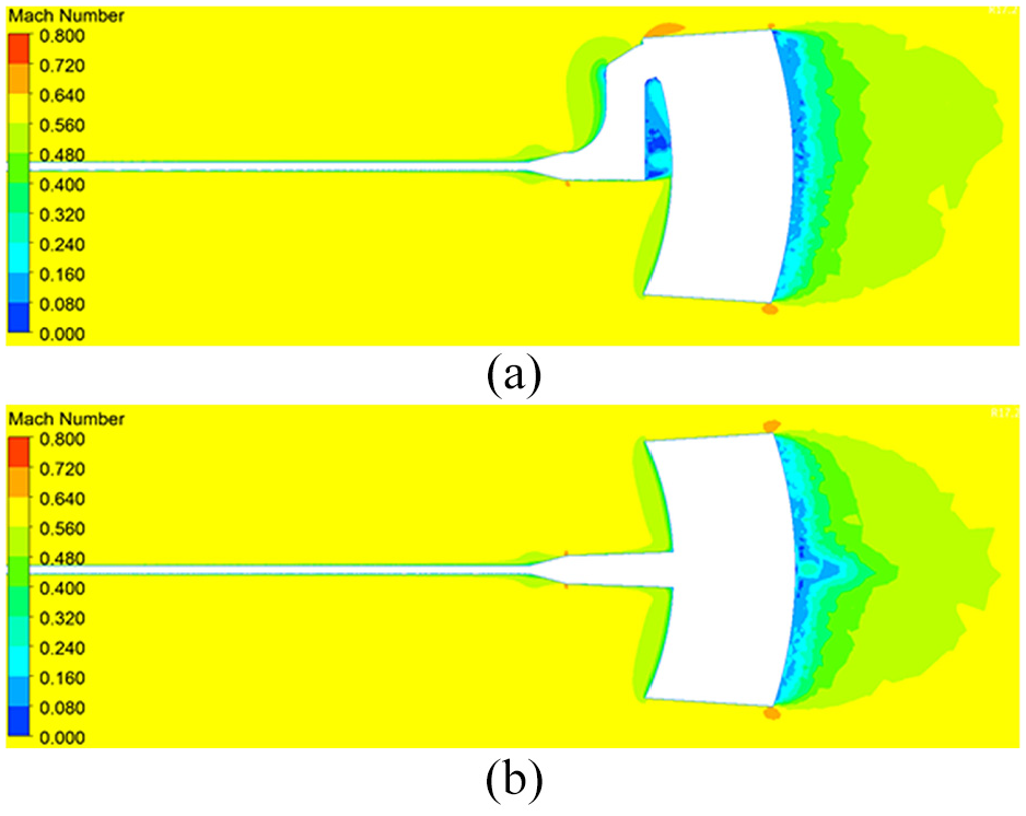
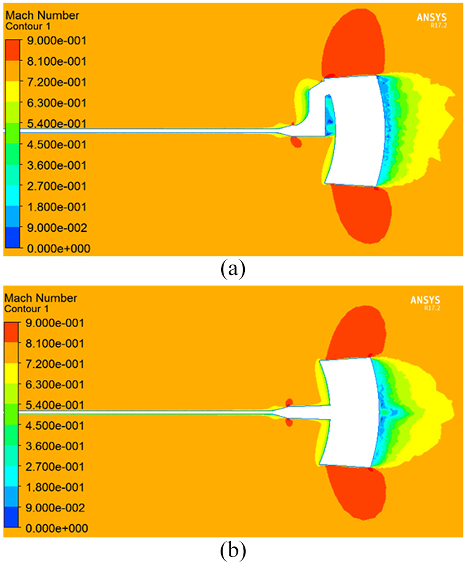
Figure 7 illustrates the definition of the probe centerline and the Mach number distribution along this line. The numerical simulation results indicate that the Mach number distribution along the probe centerline, computed using structured, unstructured, and hybrid meshes, exhibits a similar trend. However, the wall Mach number obtained from the unstructured mesh exhibits fluctuations with a magnitude of ±0.002. As depicted in Figure 8(a), the cloud of near-wall Mach numbers at the center of the probe reveals that the unstructured mesh poorly adheres to the near-wall surface, leading to discrepancies in the near-wall flow due to the presence of concavities and convexities in the wall. The numerical calculations further show that the Mach number remains relatively constant from the wind tunnel inlet to the centerline of the spinning center probe, whereas it gradually decreases from the spinning center cross-section to the centerline of the cone angle probe. Figure 8(b) corroborates the observation that the cone angle introduces a certain range of upstream airflow disturbances. The gauge centerline is the axis of the probe and is used to describe the Mach number distribution along the axis direction. In the depiction of Figure 8, the definition of the probe centerline is based on the geometric axis, and the calculation method employs integration along the probe center to obtain the distribution of Mach numbers. This method ensures that the aerodynamic characteristics in complex geometries accurately reflect the flow field characteristics.
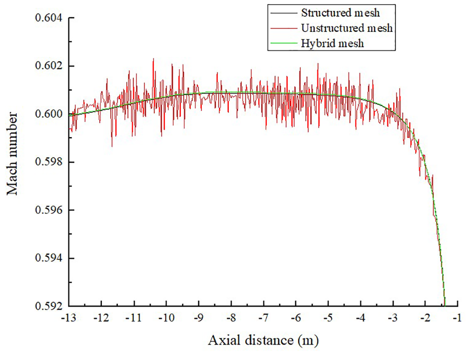
Mach number distribution curve of the probe centerline.

Mach number distribution around the probe: (a) Mach number cloud of the near-wall surface of the probe and (b) Mach number distribution from the pivot section to the cone Angle near the wall.
Influence of aerodynamic shape on quality of wind tunnel flow field
Aerodynamic shape of support structure
Figure 9 depicts the schematic representation of the aerodynamic configuration of the support structure. In Structure I, the model is composed of a strut, a dual-rotating shaft, and a bender, with all angles—head angle, side slip angle, and roll angle—set to 0°. Structure II, on the other hand, comprises a strut, a direct head, a rear axle, and a bender, and it also maintains the angles of approach, side slip, and roll at 0°.

The schematic model of Aerodynamic shape of support structure: (a) structure I (strut + double rotor + bender) and (b) structure II (strut + direct head + rearaxle + bender).
The commercial ANSYS-CFX software is employed to assess the impact of the aerodynamic shape on the flow field. 34 ANSYS Mesh software generates an unstructured mesh based on the fluid domain model constructed using the aerodynamic shape and the far-field characteristics of the mechanism. The mesh count for the calculation domain of Structure I (strut + dual rotor + bender) amounts to 5,411,300, whereas Structure II utilizes a mesh count of 3,665,600. The initial near-wall grid cell height is set to 0.001 mm, and the near-wall surface layer is refined to simulate the flow characteristics in detail. This is depicted in Figure 10, which illustrates the local area mesh. The body wall is defined as an adiabatic, non-slip wall, and the solid wall boundary condition is set with a specified level of roughness.

Computing domain and mesh.
Flow field quality
Ma = 0.60
Ma = 0.6: Represents a typical subsonic cruise condition for commercial and military aircraft, where aerodynamic efficiency and stability are critical. This regime is particularly sensitive to flow disturbances caused by support structures, making it essential for evaluating low-speed interference effects. Ma = 0.8: Corresponds to transonic flight conditions near the critical Mach number, where localized supersonic flows and shock waves may occur. This regime is crucial for assessing the dual-rotating shaft mechanism’s performance under mixed subsonic/transonic interactions, which are common during high-speed maneuvers. Ma = 0.95: Approaches the upper limit of transonic flow (near-sonic conditions), simulating extreme aerodynamic loads and compressibility effects. This tests the robustness of the optimized structure under near-critical flow separation and turbulence, ensuring its applicability to high-speed testing scenarios. In this study, Ma = 0.6, 0.8, and 0.95 were chosen for the simulations, mainly to cover typical flow conditions at low, medium, and near-sonic speeds, which are representative of the aerodynamic properties of the model at different flight speeds, in order to comprehensively assess the effect of the structure on the flow field. Repeat the experiment three times to reduce errors.
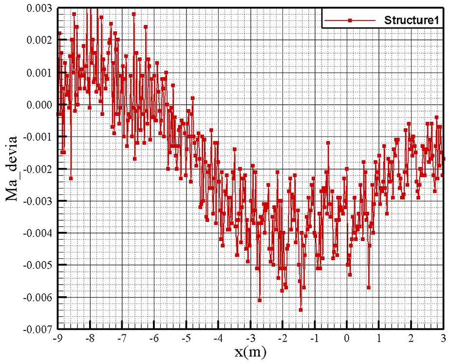
Table 2 presents the calculated flow field results for the two structural solutions under flow field calculations with an inlet Mach number of Ma = 0.6. The Mach number distribution across the inlet and outlet cross-sections of the first dual-rotating shaft demonstrates a pattern similar to that of the direct head structure, as illustrated in Figure 11. The cross-sectional Mach number distribution reveals that the attachment area of the dual-rotating shaft structure is more influenced by the gas flow. Figure 12 provides the flow field area along the central axis of the airflow, depicting the upstream Mach number distribution difference between Structure I and Structure II from the entrance of the test section to downstream of 12 m. The results indicate that, when compared to the Structure II with the direct head, the Structure I with the dual-rotating shaft exhibits a small fluctuation in the upstream Mach number distribution along the central axis, with a maximum absolute difference of 0.008.
Results of numerical calculations. (Ma=0.6)

Distributions of Mach number at Ma = 0.60 in the mid-section: (a) structure I and (b) structure II.

Difference in Mach number in the centerline of the probe tubes between structure I and structure II. (Ma=0.6)
Ma = 0.80
Table 3 outlines the calculated flow field results for the two structural solutions under flow field calculations with an inlet Mach number of Ma = 0.8. Consistent with the findings at Ma = 0.6, the Mach number distribution across the inlet and outlet cross-sections of the first dual-rotating shaft maintains a similar pattern to that of the direct head structure, as depicted in Figure 13. The cross-sectional Mach number distribution suggests that the gas flow perturbation is more pronounced in the attachment region of the dual-rotating shaft structure. As shown in Figure 14, similar to the behavior at Mach 0.6, the Structure I of the dual-rotating shaft along the central axis exhibits a small fluctuation in the upstream Mach number distribution, with a maximum absolute difference of 0.01.
Results of numerical calculations. (Ma=0.8)

Mach number distribution in Middle cross-section at Ma = 0.80: (a) structure I and (b) structure II.
Difference in Mach number in the centerline of the probe tubes between Structure I and Structure II. (Ma=0.8)
Ma = 0.95
Table 4 illustrates the calculated flow field results for the two structural solutions under flow field calculations with an inlet Mach number of Ma = 0.95. The Mach number distribution across the inlet and outlet cross-sections of the first dual-rotating shaft displays a similar pattern to that of the direct head structure, as visualized in Figure 15. The cross-sectional Mach number distribution indicates that the dual-rotating shaft structure is more susceptible to gas flow disturbances in its vicinity. As depicted in Figure 16, akin to the behavior at Mach 0.8, the Structure I of the dual-rotating shaft along the central axis exhibits a small fluctuation in the upstream Mach number distribution, with a maximum absolute difference of 0.01.
Results of numerical calculations.


Mach number distribution in Middle cross-section at Ma = 0.95: (a) structure I and (b) structure II.

Difference in Mach number in the centerline of the probe tubes between Structure I and Structure II (Ma=0.95)
This section presents a comparative analysis of the Mach number distributions for Structures I and II. Under identical inlet Mach number conditions, the maximum difference in Mach number distribution along the central axis of the flow for Structure I is found to be 0.008, which falls short of the target threshold of less than 0.005. Considering the influence of the flow field behind the model area, the location of the model area, and the minimal impact of different model support structures on the forward flow, a Mach number difference of no more than 0.005 is selected as the target value. At the same time, in order to optimize the structural shape of the dual axis mechanism and reduce the impact of the mechanism on the flow field interference, it is required that the difference between the interference of the dual axis mechanism support form and the direct head support form on the flow field interference in the model area should not exceed 0.005. To ensure that the structural optimization reduces the disturbance of the flow field to an acceptable range, so as to obtain highly accurate test data. Consequently, subsequent efforts focus on the structural and aerodynamic shape optimization of Structure I to address this discrepancy. Each round of optimization refines variables based on previous results. In this section, the probe rod model is validated by numerical partitioning of structured, unstructured, and hybrid meshes to ensure the accuracy and consistency of the simulation calculations.
Dual-rotating shaft optimization
Structure optimization
The optimization model is conFig.d with a strut, dual rotor, and bending knife, with the angles of yaw, sideslip, and roll set to 0°, as illustrated in Figure 17. The optimization process primarily concentrates on refining the structural design of the front shaft arm, which involves trimming the arm, such as reducing its width or minimizing cross-sectional blockage. The aerodynamic shape of the mechanism and the far-field characteristics of the fluid domain model are established using ANSYS Mesh software, as depicted in Figure 18. The near-wall attached surface layer is refined to capture the flow characteristics of the near-wall surface. The total number of meshes is 3,376,300.
Wind tunnel test section model of structure I(strut+double rotor+bender): (a) original and (b) optimized.
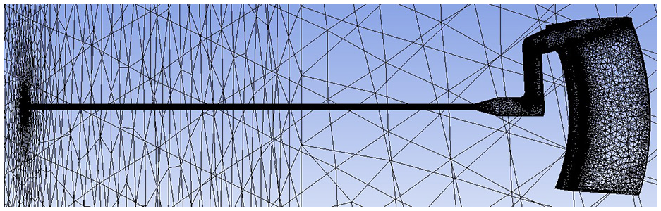
Structure 1 optimized model mesh.
Figure 19 depicts the Mach number distribution curve along the probe centerline for flow conditions with inlet Mach numbers of Ma = 0.6, 0.8, and 0.95. It shows a diminishing near-wall Mach number along the probe’s axial length, with the most significant reduction occurring near the front axial cone of the probe centerline. Figure 20 illustrates the difference in Mach number distribution between the original and optimized versions of Structure I for the upstream central axis of the downstream flow field, from the inlet of the test section to 12 m downstream. Calculation results under these flow conditions indicate that, compared to the direct head of Structure II, the optimized Structure I design demonstrates a maximum difference in Mach number distribution along the central axis of the airflow upstream of 0.005, indicating an improvement over the original Structure I design. This section focuses on the optimization of the structural design of the front axle arm, including the reduction of the width of the axle arm and the reduction of the cross-sectional obstruction rate, in order to achieve structural lightweighting and reduce the interference with the flow field.

Structure II, Structure I original and optimized probe tube centerline Mach number distributions: (a) Ma = 0.60,(b) Ma = 0.80, and (c) Ma = 0.95.

Structure I original and optimized probe centerline Mach number differentials: (a) Ma = 0.60, (b) Ma = 0.80, and(c) Ma = 0.95.
Aerodynamic profile optimization
Optimization ideas
From the above, it can be seen that the base scheme of the dual-rotating shaft mechanism has greater interference with the upstream flow field under inlet Mach number 0.8 and 0.9 conditions. Additionally, the structural strength in the front shaft is subjected to greater aerodynamic load in the rest of the state angle. In order to make the optimization process more controllable, a step-by-step optimization method is adopted in this study. Compared with the global optimization, the step-by-step optimization can gradually reduce the interference of the structure on the flow field, and avoid the computational instability and convergence difficulty caused by introducing too many variables at one time. The term “Ma_deriva” in Figure 21 is defined as the difference in Mach numbers between two different cases. It is used to measure the degree of influence of different structures on the flow field disturbance before and after optimization. Figure 21 depicts the optimized zone of the shape in the front shaft for the base scheme of the dual-rotating shaft mechanism with a 20°, and the idea of the optimization of the aerodynamic shape is as follows:
Decrease the axial width of the front shaft crutch arm.
Reduce the thickness of the front shaft crutch arm.
Shift the axial position of the front shaft crutch arm away from the center of rotation
Perform numerical simulation optimization to assess the variation under incoming flow Mach number 0.9 conditions.

Definition of the front axle profile optimization region.
Comparison of front axle round 1 optimization
Figure 22 illustrates the comparison of the first round of optimization models. The axial width of the front shaft V32 crutch arm is reduced, and the thickness of the crutch arm is increased, resulting in a maximum thickness of the front shaft crutch arm increasing from 200 to 430 mm. It can be observed from the Mach number distribution curve along the center line of the probe tube that the increase in the thickness of the axial bending arm of the front end in the first round of optimization (scheme YH54) significantly affects the axial region of the upstream flow field from −3 to 3 mm. The Mach number of the probe tube optimized in the first round decreases more rapidly on the central axis, as depicted in Figure 23(a). Figure 23(b) shows the difference in Mach number along the centerline of the probe tube between YH54 and V32 at the inlet Mach number Ma = 0.90. The results indicate that the Mach number difference in the first round optimization of the YH54 central axis tube surface is more pronounced than in the baseline scheme V32. At 0.008–0.018 of the base scheme V32, the target of 0.005 is not achieved. From Figure 23(c) and (d), it is evident that the thickening of the front shaft arm in the first round of optimization for YH54 has a more significant influence on the upstream flow field compared to the baseline scheme V32.

Comparison of optimized models in round 1.

The influence of optimized models in round 1 on flow field quality. (a) Mach number distribution curves on the centerline of the probe tube. (b) Mach number difference between YH54 and V32 probe centerlines. (c) V32 Base Plumb Horizontal Mach. (d) The first round of optimization. YH54 Lead Plane and Horizontal Mach Number.
Comparison of front axle round 2 optimization
Figure 24 show the second round of optimization models. Building upon the previous round’s optimization scheme YH19, the current iteration involves repositioning the axial location of the front shaft flexion arm rearward. Figure 25(a) illustrates the Mach number distribution curve along the centerline of the probe tube. The results indicate that the second round of YH61 optimization has shifted the axial position of the front shaft bending arm backward and away from the rotation center, thereby diminishing its impact on the upstream flow field. As depicted in Figure 25(b), the Mach number difference along the center shaft tube surface for scheme YH61 in the second round of optimization is 0.0052 at a distance of 2.8 m, which is remarkably close to the target of 0.005. In comparison to YH59 from the first round of optimization, YH61 in the second round has a reduced influence on the upstream flow field due to the backward movement of the axial position of the front axle inflection arm, as evidenced in Figure 25(c).

Comparison of optimized models in round 2.

The influence of optimized models in round 2 on flow field quality. (a) Mach number distribution curves on the centerline of the probe tube. (b) Mach number difference between YH61 and V32 probe centerlines. (c) Round 2 optimization YH61 Pilot Plane and Horizontal Plane Mach Number.
Comparison of front axle round 3 optimization
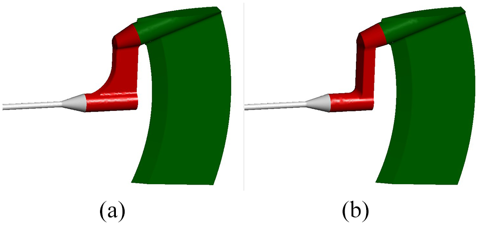
Figure 26 depicts the third round of optimization models. In contrast to the second round, the rotation center of the mechanism is elevated by 400 mm, the cantilever length of the front bridge is shortened, and the cantilever’s stiffness is increased to a certain extent. Additionally, the front bridge cantilever is moved forward toward the center of the cantilever. Figure 27(a) illustrates the Mach number distribution curve along the centerline of the probe tube. The results indicate that the YH81 scheme from the third round of optimization is fundamentally aligned with the Mach number distribution along the centerline of the dual-rotating shaft probe tube. As illustrated in Figure 27(b), under the condition of a flow Mach number Ma = 0.90, the Mach number difference between the probe tube centerline of the YH81 optimization scheme and the V32 base scheme is 0.005 at 2.8 m, meeting the design requirement of 0.005. As can be seen from Figure 27(c), in comparison to the optimization scheme YH61 from the second round, the optimization scheme YH81 from the third round raises the probe 400 mm upwards, which mitigates the interference of the upstream flow field.

Comparison of optimized models in round 3.

The influence of optimized models in round 3 on flow field quality. (a)Mach number distribution curves on the centerline of the probe tube (b)Mach number difference between YH81 and V32 probe centerlines. (c) Round 3 optimization YH81 Pilot Plane and Horizontal Plane Mach Number.
Comparison of front axle 4th round optimization
Figure 28 illustrates the fourth round of optimization models. In contrast to the third round, modifications include a 357.8 mm increase in the elevation of the center rod, with a 42.2 mm reduction in the probe’s height. Additionally, the front shaft cantilever was tilted backward to enhance cantilever stiffness. Figure 29(a) depicts the Mach number distribution curve along the centerline of the probe tube. The results reveal that, following the fourth round of optimization for the YH91 scheme, the rotation center of the mechanism is elevated by 357.8 mm. The Mach number distribution along the centerline of the dual-rotating probe tube remains largely unchanged, but the interference of the Mach number in the axial direction of −2 to 3 m is gradually intensified. Under the condition of an inlet Mach number Ma = 0.90, the Mach number difference of the probe tube centerline between the YH91 optimization scheme and the V32 reference scheme indicates that the Mach number difference at 2.8 m is 0.005, which meets the design goal of 0.005, as shown in Figure 29(b). From Figure 29(c), it is evident that, compared to YH81 from the third round of optimization, YH91 from the fourth round of optimization is elevated by 400 mm, which slightly increases the interference of the upstream flow field.
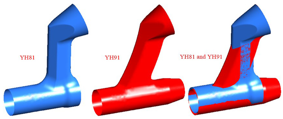
Comparison of optimized models in round 4.

The influence of optimized models in round 4 on flow field quality. (a) Mach number distribution curves on the centerline of the probe tube (b) Mach number difference between YH91 and V32 probe centerlines. (c) Round 4 optimization YH91 Pilot Plane and Horizontal Plane Mach Number.
The numerically calculated data for the static pressure and Mach number on the centerline of the probe are given in Table 5
Static pressure and Mach number data on the centerline of the probe.

Machining and testing
The construction design of the double-rotating shaft mechanism is carried out to complete the structural design optimization, and the processing and manufacturing are carried out according to the construction drawing. In the manufacturing process, emphasis is placed on controlling the dimensions and accuracy of the front support plate, middle support and other structures, and the 3D model of the final optimization results is imported into the machining center for reshaping and modeling, so as to ensure that the manufactured object remains the same as the simulation model, as shown in Figure 30.

Front support plate processing and manufacturing.
After the manufacturing is completed, the components are assembled and the mechanism is run and debugged to ensure that the operation indicators of the mechanism are qualified, as shown in Figure 31.

Dual-rotating shaft mechanism assembly and forming.
In order to verify the optimization results of the aerodynamic shape of the structure, the actual interference of the dual-rotating shaft mechanism on the flow field in the test area is measured. In an existing wind tunnel equipment, the double-rotating shaft mechanism is installed in the wind tunnel, as shown in Figure 32. An axial probe is installed at the front end of the double-rotating shaft mechanism, and a pressure measuring point is set on the axial probe to measure the local section pressure of the flow field in the test area, so as to calculate the Mach number of the local section, as shown in Figure 33.

Double-rotating shaft mechanism installed in a wind tunnel.

Flow field interference test model.
Wind tunnel equipment was used to complete the test of incoming Mach numbers of 0.5, 0.6, 0.7, 0.8, and 0.85 in the test area. The test results are shown in Figure 34. According to the test results, we calculated the difference between the measured Mach number and the theoretical Mach number (i.e. the interference △Cma), as shown in Figure 35. According to the test results, it can be seen that it has a certain effect on the aerodynamic shape optimization of the double rotating shaft structure, and reduces the influence of the double rotating shaft support structure on the flow of the test area.

Test results of different Mach numbers.

Difference in Mach numbers: (a) 0.5, (b) 0.6, (c) 0.7, (d) 0.8, and (e) 0.85.
Evaluating the discrepancies between empirical test outcomes and theoretical predictions is essential for several reasons. Primarily, inadequate manufacturing precision poses a significant challenge. The deviations in dimensional accuracy from the ideal specifications can lead to inconsistencies with the simulation models, as real-world production processes often fail to achieve the flawless geometries assumed during computational modeling.
Secondly, during the assembly of mechanisms, physical irregularities such as holes and gaps at screw installation points and around local rectifier cover plates can diverge significantly from the idealized conditions represented in simulation models. These imperfections can induce localized airflow disturbances that were not accounted for in the theoretical calculations, thereby affecting experimental results. Specifically, in complex aerodynamic structures like dual-rotating shaft mechanisms, such anomalies can critically disrupt airflows, impacting overall performance metrics.
Furthermore, the inherent instability in the flow field generated by wind tunnel equipment introduces another layer of variability. Fluctuations in the incoming flow’s Mach number introduce additional uncertainties that are absent in theoretical analyses, which typically assume a constant Mach value. This disparity between the dynamic conditions encountered in practical testing scenarios and the static assumptions made in theoretical models contributes significantly to the divergence between predicted and actual outcomes.
Overall, optimizing the aerodynamic design of dual-rotating shaft mechanisms aims to mitigate these flow field interferences within the test area. By refining the structural configurations, it is possible to minimize adverse effects caused by both manufacturing inaccuracies and assembly irregularities. This approach not only enhances the fidelity of experimental results but also provides valuable insights for future engineering endeavors. Consequently, these efforts hold considerable significance for advancing similar research and development activities, contributing to more accurate simulations and efficient designs in aerospace engineering and beyond.
The abbreviations used throughout the text are shown in Table 6.
Abbreviation list.

Conclusion
A novel dual-rotating shaft mechanism is designed to enable continuous attitude adjustment simulation of aircraft, thereby significantly contributing to the advancement of aircraft aerodynamics in wind tunnel experiments. The impact of the mechanism’s aerodynamic shapes on wind tunnel flow field quality is comprehensively analyzed to refine the design. Consequently, numerical simulation and iterative optimization of the support structure are conducted to enhance flow field quality, providing a valuable reference for aircraft development in wind tunnel testing.
The Mach number distribution trends at the probe rod centerline from structured, unstructured, and hybrid meshes exhibit a comparable pattern, yet the wall Mach number from the unstructured mesh shows fluctuations of ±0.002. Considering the structural complexity of the support mechanism, a hybrid mesh is predominantly utilized for numerical investigations of the biaxial mechanism.
A numerical comparative analysis of the two original structural solutions, Structure I and Structure II, is conducted. The results indicate that within the range of −9 to 3.0 m, the surface Mach number difference between the dual-rotating shaft mechanism and the direct head mechanism is 0.0025 at incoming Mach numbers of 0.6 and 0.8. Moreover, the Mach number difference on the center shaft tube surface is 0.0025 at 0.6, 0.0058 at 0.8, and 0.0082 at 0.9, falling short of the target of 0.005.
Multiple rounds of iterative aerodynamic shape optimization are performed, comparing axial width, thickness, and axial position of the front crutch arm, along with the Mach number difference at Mach 0.9. The results indicate that reducing the axial width and thickness of the front shaft crutch arm and positioning it further from the rotor center can alleviate upstream interference. The surface Mach number difference between the optimized schemes 81 (elevated by 400 mm) and 91 (raised by 357.8 mm) at 2.8 m is 0.005, meeting the requirements. However, considering the cantilever beam’s rigidity and structural safety, the optimized scheme YH91 is deemed suitable. The study provides a theoretical basis for exploring the model analysis of dual-rotating shaft mechanisms at higher Mach numbers in the future.
Footnotes
Handling Editor: Divyam Semwal
Funding
The author(s) received no financial support for the research, authorship, and/or publication of this article.
Declaration of conflicting interests
The author(s) declared no potential conflicts of interest with respect to the research, authorship, and/or publication of this article.