
Abstract
The compressor blades in gas turbines are subjected to long-term dynamic stress, and the blades sustain a certain degree of damage. This high-cycle fatigue damage of the blade accumulates to a certain extent, the crack will appear. The blade will fracture after the crack gradually expands to a certain size. A novel evaluation approach of the high-cycle fatigue life for the cracked blade is developed. This paper analyzes the influence of the different crack sizes on the vibrational characteristics and fatigue lifetime of the blade. Considering the aerodynamic and centrifugal loads, the finite-element model of the cyclic symmetric impeller structure is constructed. A time-varying aerodynamic load mapping method and a modeling approach for contact interactions at the blade root and dovetail slot are proposed for better dynamic stress calculations. The transient dynamics method is used to solve the vibration response of the blade considering Rayleigh damping, and the results are obtained and compared to the experimental results. The reasonable structural damping is selected to lay a foundation for the analysis of blade fatigue lifetime. Goodman and S-N curves are adopted to estimate the blade fatigue lifetime. The results show that the appearance of a crack leads to the reduction in the first three natural frequencies of the blade; when the crack occurs and the crack size increases, the position of the maximum dynamic stress shifts from the blade root to the two ends of the crack, and the mean dynamic stress
Introduction
The dynamic blade is a key component in the gas turbine compressor, subjected to centrifugal load, aerodynamic force, and other forces during operation. 1 Under the influence of these complex forces, the blade is prone to vibration and High-Cycle Fatigue (HCF) damage, which affects the service life of the blade.2–4
Recent studies have significantly advanced the understanding of blade vibration characteristics. Rout and Hota 5 studied the nonlinear free vibration of the turbine blades. Nan et al. 6 investigated the vibration characteristics of compressor blades under different working conditions. Based on the S-N curve, the fatigue lifetime of the blade was investigated. Fallah Sheykhlari et al. 7 studied gas turbine blade fracture surfaces, concluding that fatigue mechanisms were the primary cause of failure. Vo et al. 8 presented a thermo-fluid-structural analysis program to estimate the fatigue lifetime of the gas turbine blade. He et al. 9 proved the reason for turbine blade failure according to the different analysis approaches, some suggestions for increasing the service life of steam turbine blades are put forward. Zucca et al. 10 proposed a method for calculating the friction force at the root joint of the blade and assessed its influence on the blade dynamics. This method is currently applied for nonlinear dynamic analysis of the turbine blades. Farghaly et al. 11 investigated the complexity of the aerodynamic performance of aircraft propeller blades by generating a three-dimensional unstructured grid using GAMBIT software. Fu et al. 12 built a numerical analysis model for the blade, and calculated the vibrational characteristic under the centrifugal and aerodynamic loads; then the improved fatigue model is applied to forecast the fatigue lifetime of the blade under the actual operating conditions. Rani and Agrawal 13 analyzed the fatigue lifetime of turbine blades under cyclic loading. The numerical model based on the Smith-Watson-Topper, Strain life, and Morrow average stress theory was established to predict damage to the blade.
High-cycle fatigue, mechanical damage, corrosion, and water erosion may lead to cracks in the blade. These cracks can significantly reduce the blade’s service life.14–17 Farghaly et al. 18 investigated the erosion of propeller engine blades and their impact on blade profile degradation. Marandi et al. 19 studied particle impact damage (FOD) on aircraft blade leading edges. Wu et al.20,21 studied the influence of crack location and depth on blade vibration characteristics. Salehnasab and Poursaeidi 22 investigated the propagation mechanism of fatigue cracks in first-stage gas turbine blades made of CM186LC material. Xiong et al. 23 presented a crack fault diagnosis index of the rotating cracked blade with breathing influence according to the vibration energy method; and based on the energy response analysis, the influences of crack depth on the nonlinear vibrational characteristic of the rotating cracked blade were studied. Bhamu et al.24,25 explored the influence of different blade crack depths on the natural frequencies and critical speed of the blade. Moradi et al. 26 investigated the 13th row of the T56 compressor blade, and computed the amount of cycles required for the crack propagation and the blade fracture by Paris law. Based on FRANC3D and the ANSYS platform. Wang et al. 27 investigated the crack growth process of aero-engine blades under centrifugal and aerodynamic loads. Salehnasab et al. 28 studied the thermal fatigue lifetime of cracks in a gas turbine engine under elastic-perfectly plastic conditions, the investigators accurately predicted fatigue lifetime by using finite element analysis. Wei et al. 29 investigated the fracture mechanism of the low-pressure rotor of the steam turbine to find the reason for the crack and the preventive measures that can be taken. Khan and Sasikumar 30 explored the microstructure of low-pressure steam turbine blades to probe the crack propagation mechanism. Graciano et al. 14 applied a new method to assess the damage and service life of the fractured blades. The results show that the performance of steam turbine blades will change with the change in crack size. Chowdhury et al. 31 introduced thermal performance and failure analysis of gas turbines. Yang et al.32–35 researched an improved analytical model of breathing cracks for rotating blades. It has been observed that as the crack position moves closer to the blade root, the crack depth increases, resulting in reduced stiffness of the rotating blade and a corresponding decrease in its resonance frequency. In addition, many other parameters, such as revolution speed and aerodynamic amplitude, significantly affect the vibration of cracked blades.36–40 The dynamic process of crack propagation has also received a lot of attention in the past decades.41–45
Many parameters affect the fatigue lifetime of a blade, and crack size is one of the most significant factors. When a blade in the compressor produces cracks at the beginning, the impact on the operation and detection data is not significant due to the small crack, which is often difficult to detect. The remaining life of the blade under the different crack sizes is important for blade health monitoring and life management. Researchers have conducted much work on blade vibration and fatigue lifetime, but research on the vibration and life under the various typical crack sizes during crack expansion is scarce. In this paper, a dynamic blade model with different typical crack sizes is established, and the inherent characteristic of the blades is analyzed by the finite element method. The centrifugal and aerodynamic loads are applied to the blade to evaluate the fatigue lifetime. It is novel to develop the assessment approach of the fatigue lifetime for the cracked blade. The research work has essential value for the vibrational response calculation and fatigue lifetime assessment of the blade.
Calculation method of vibration responses
To evaluate the high-cycle fatigue life of the dynamic blades, the vibration characteristics of the blade should be analyzed first. Blade vibration analysis includes the intrinsic characteristics analysis and the vibration response calculation.
Intrinsic characteristics analysis and transient dynamics
The structural dynamics governing the equation of the blade is

where

The solution of equation (2) is

where A is the amplitude; ω is the circular frequency; α is the initial phase of the system. Substituting the equation (3) into the equation (2), we can obtain

Then, the natural frequency of the structure can be expressed as

For the damped model, if the external force is not considered, equation (1) can be expressed as

Let the solution of equation (6) be

Substituting equation (7) into the equation (6), we can obtain

The necessary and sufficient condition for the existence of nonzero solutions in equation (8) is

Equation (9) is a quadratic algebraic equation concerning λ, which has 2n characteristic roots, λ i (i = 1, 2, 3 … 2n).
In the calculation of harmonic response analysis, the transient vibration generated at the start of the excitation is ignored, that is, only the vibration after the steady state is considered. Researchers can analyze the dynamic characteristics of the structure by harmonic response analysis. They can also evaluate its vibration resistance.
In the harmonic response analysis, the structural dynamics equation can be seen in equation (1). The vibrational displacement can be expressed as

where qmax is the maximum displacement; i is the unit complex number; ω is the circular frequency of the excitation force; φ is the phase angle of displacement; t is the time. Similarly, the load can be expressed as

where Fmax is the load amplitude; ψ is the phase angle of the load.
Because the qmax and φ corresponding to each node on the structure may be different, equations (10) and (11) can be rewritten as complex form, respectively.


Then we can get


Substituting equations (14) and (15) into equation (1), the basic equation of harmonic response can be obtained

where F1 and F2 are the real part and the imaginary part of the harmonic load, respectively; q1 and q2 are the real part and imaginary part of displacement, respectively. According to equation (16), when the imaginary part of the applied load is not zero, the solution obtained by the calculation of the harmonic response is in the complex form.
The transient dynamics analysis will be briefly introduced below. The basic equations of motion are shown in equation (1). The direct integral approach is adopted to obtain the solution of equation (1). In an ultrashort time span (Δt), the velocity and displacement are presented as equations (17) and (18)


where α and δ are the Newmark integral parameters.
Equation (1) at time t n +1 is denoted as

Substituting equations (17) and (18) into equation (19) and introducing the related parameters leads to


where


and then we can get

The initial conditions

where

where n is the coefficient of damping decay, the default value is 0.1.
Rayleigh damping is adopted in the analysis, and the damping is written as

Where α0 and α1 are the mass and stiffness damping coefficients, respectively. The Rayleigh damping at each order mode is expressed as

Blade fatigue lifetime
Fatigue load is a dynamic load that causes fatigue failure of the structure. It is mainly divided into alternating load and random load. The alternating load shows that the size and direction of the load change periodically with time, and the stress of the structure under the alternating load is alternating stress. The random load is that the size and direction of the load change randomly with time.
Figure 1 is a curve of alternating stress changing periodically with time, and a periodic stress change process is defined as a stress cycle. The cyclic stress characteristics are typically described by the maximum stress σmax, the minimum stress σmin, and period T (or frequency f = 1/T). Due to the absolute value of the σmax and the σmin being equal and the sign being opposite, it is called symmetrical cyclic alternating load. The stress amplitude is σ a ; the vibrational amplitude of stress (Peak-to-Peak Value) is Δσ; the average stress is σ m . The relationship between them can be expressed as

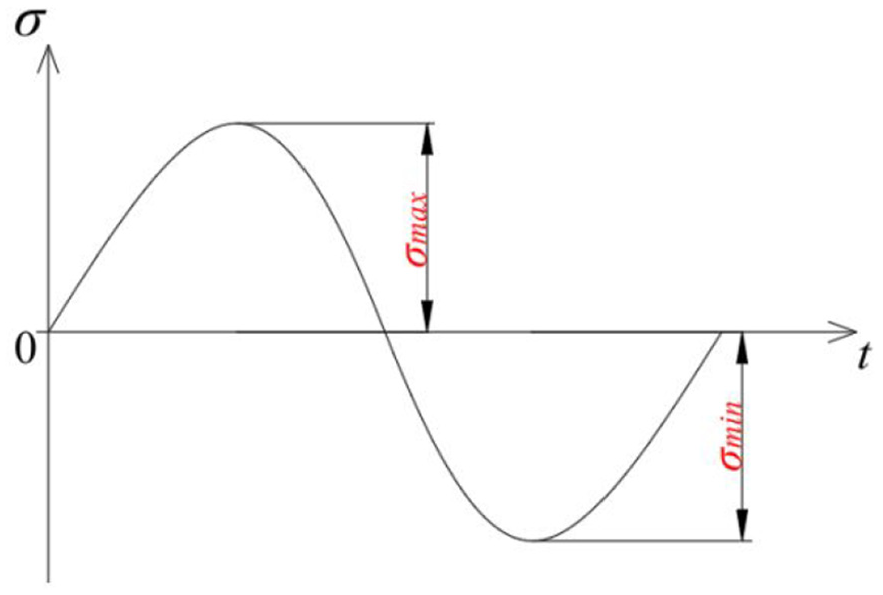
Symmetric cyclic alternating load.
The σ a refers to the amplitude of alternating stress in a cycle, which is often the important cause of the fatigue failure of metal structures.
Under the combined action of dynamic load and static load, the stress curve of the component with time is shown in Figure 2. The asymmetry of cyclic stress is generally quantified by the ratio R of the minimum stress to the maximum stress. R is the stress ratio, also known as the symmetry coefficient, that is written as

When R = −1, the cyclic stress is defined as symmetric cyclic stress; when R ≠ −1, it is defined as asymmetric cyclic stress.

Asymmetric cyclic alternating load.
The average stress is an important factor affecting the fatigue resistance of the structure. Decreasing the mean stress can increase the fatigue strength, whereas increasing the mean stress can decrease the fatigue strength. Therefore, in the analysis of fatigue strength and life, for a specific cyclic stress level, it is necessary to determine σ a and R, or σmax and σ m , and sometimes σmax and σmin can be used to represent the cyclic stress level.
In general, the smaller the stress amplitude of the cyclic loading of the structure, the longer the number of cycles to fatigue failure. The S-N curve is usually adopted to describe the relationship between the stress amplitude of the structure and the number of cycles experienced. The S-N curve is also known as the stress-life curve, and it is applied to characterize the relationship between stress and fatigue lifetime. If the structure can withstand more than 106 cycles, it is usually called high-cycle fatigue. On the contrary, it is called low-cycle fatigue. In the case of low-cycle fatigue (LCF), the structure will undergo plastic deformation at local positions. The S-N curve of the blade material in this paper is shown in Figure 3. 46 The abscissa is the number of cycles, denoted by N, and the ordinate is the Stress amplitude under cyclic loading, usually denoted by S. When the stress is reduced to a critical value, the S-N curve tends to be horizontal, which indicates that the structure can undergo numerous cycles without fatigue failure.

S-N curve of the blade (R = −1).
The Goodman curve is widely applied in engineering practice, therefore, we use this curve to calculate and analyze in this work. The Goodman curve is shown in Figure 4. 47 This kind of diagram is also called the constant life diagram or the fatigue limit diagram. Its engineering significance is that, based on the given average stress level and the known symmetrical cyclic fatigue limit, the fatigue limit stress amplitude corresponding to the stress level is calculated, which helps us to predict the fatigue resistance of materials under specific stress conditions more accurately. When the stress amplitude and the average stress are within the Goodman curve and the N life range, fatigue failure will not occur. The fatigue lifetime of dynamic blades is mostly calculated by high-cycle fatigue (HCF). Therefore, the stress mean value and the stress amplitude during steady state in the dynamic stress diagram, as important parameters of the HCF, are calculated. Based on the Goodman curve, the expression of the equivalent effect stress is written as

where
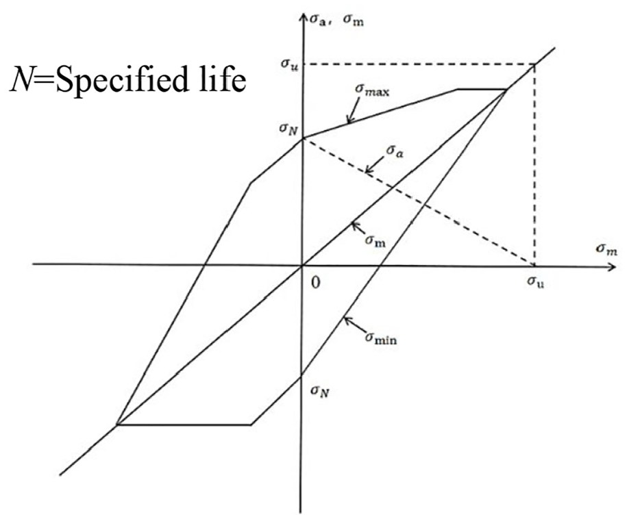
Goodman curve.
Modeling of blade structure
Geometric model
The whole cyclic impeller model of the gas turbine compressor is established, as shown in Figure 5. There are 37 blades in the whole impeller, a blade without a crack (Figure 6) and a blade with a certain crack size (Figure 7) are taken as the research object. The crack shape and parameter are shown in Figure 8, where the crack length is a (mm) and the crack depth is c (mm). Three blade models with different crack sizes are established, and the crack parameters are shown in Table 1 with a width of 222.16 mm and a height of 478.98 mm for the blade.

Geometric model of the whole ring-bladed disk.
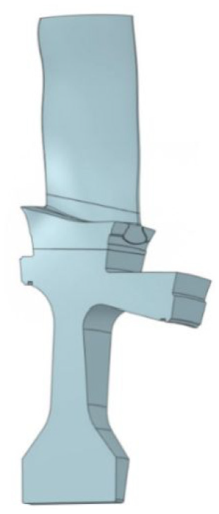
Geometric model of the blade without crack.

Geometric model of the blade with crack.

Crack shape and parameter.
Crack parameters.

According to fracture mechanics and the theory of material mechanics, crack initiation and propagation are influenced by factors such as stress state, material properties, and crack geometry. Based on these considerations, cracks were introduced in the lower back arc region of the blade. This area is prone to stress concentration due to the combined effects of fluid impact and mechanical loads. When local stress exceeds the material’s strength limit, cracks are likely to initiate and propagate in this region. The selection of this location is theoretically justified and effectively represents typical failure modes observed in real engineering applications.
Finite element analysis
The finite element analysis is performed using ANSYS Workbench 2020 R2, where material properties are assigned, meshing is completed, and the displacement/load boundary conditions are applied. The blade material is specified as X5CrNiCuNb16-4, while the disk material is 26NiCrMoV14-5Mod, both with a Poisson’s ratio of 0.3. The mesh was generated using the Mesh module integrated in Ansys Workbench. Solid187 tetrahedral elements are selected due to their superior performance in high-precision modeling of complex geometries. The augmented Lagrangian method is employed to model contact interactions between components, ensuring effective constraint enforcement and numerical stability. A friction coefficient of 0.3 is adopted to simulate realistic interfacial contact behavior. These parameter settings are carefully determined based on engineering practices and relevant research to guarantee the reliability and physical significance of the computational results.
In engineering simulations, excessively coarse meshes may compromise accuracy, while overly refined meshes increase computational costs. Therefore, a mesh independence study is essential to evaluate the sensitivity of results to mesh density. Solution convergence is achieved when further mesh refinement produces variations within acceptable tolerances. To balance computational accuracy and efficiency, six blade models with varying mesh densities were established (see Table 2). The mesh independence verification was conducted using the ANSYS meshing module. In the study, the centrifugal load with a speed of 3000 RPM was selected to analyze the inherent characteristics of the blade. By comparing the 1st inherent frequency (First inherent frequency) changes of the six models, it was judged whether the frequency results were affected by the number of meshes.
Comparison of the number of different meshes and the 1st inherent frequency (no crack).

The calculation results of the 1st inherent frequency of different meshes are given in Table 2. It can be seen from Table 2 that the calculation results of different meshes are not much different, and the inherent frequency after Mesh 3 tends to be stable, with a maximum difference of only 0.025%. Therefore, the frequency results of the blade are not affected by the number of grids when the number of grids exceeds 124,734. However, the calculation time will gradually increase with the increase in the number of meshes. Considering the calculation accuracy and the cost comprehensively, the appropriate mesh density is adopted in this research. To study the local characteristics of crack-related regions for the cycle symmetry structure, the crack-related regions of the blade root are subjected to grid encryption; tetrahedrons are applied as the element type; the finite element analytical model after the meshing includes 188,269 nodes and 127,211 elements, as shown in Figure 9. Figure 10 shows grid encryption of the crack-related area in the blade root with the crack parameter a = 12 mm and c = 5 mm. A surface-surface contact is applied between the blade root and the rim groove of the impeller with a coefficient of friction of 0.3; the displacement constraints and the centrifugal load of 3000 RPM (Revolutions per minute) are applied to the structure. After this, the aerodynamic load will be exerted on the structure for the mode analysis and the life calculation.

Finite element analytical model of cycle symmetry structure.

Grid encryption of the crack-related area in the blade root: (a) grid encryption in the blade root and (b) local grid encryption near the crack.
Vibrational and fatigue lifetime analyses
Modal analysis
In this study, we use the three-dimensional solver ANSYS CFX to calculate the aerodynamic load distribution on the blade surface, solving the full-annular unsteady Navier-Stokes equations to ensure the accuracy and reliability of the aerodynamic load calculations. Regarding the boundary conditions for the numerical simulations, the inlet boundary conditions are specified with total pressure, total temperature, and velocity direction as inputs, given in a radial distribution format to match actual operating conditions. The outlet boundary condition is set with an exit static pressure boundary, also specified in a radial distribution format. The hub, casing, and blade surfaces are applied with no-slip solid wall boundary conditions. Furthermore, to account for the effect of the stator’s circumferential non-uniform distribution and to preserve the circumferential asymmetry, the steady-state calculations use the Frozen Rotor interface condition, while the unsteady calculations employ a transient interface condition to accurately capture the unsteady aerodynamic effects. The dynamic blade is subjected to the centrifugal force and aerodynamic force. The centrifugal force is the body force of the blade at the working rotating speed, and it can be calculated. The dynamic frequencies under the centrifugal load and the average value of the aerodynamic load should be calculated first for vibration analysis. When the blade is running at a stable rotating speed, it is subjected to a constant centrifugal force; the aerodynamic forces acting on the blade include the mean part and the time-varying part, and the aerodynamic mean part causes the bending and static deformation of the blade. The modal analysis of the blade under the action of centrifugal load and the aerodynamic mean load will be carried out in this section, and the distribution of the aerodynamic mean load on the blade surface is shown in Figure 11. The effect of crack on the first three order static frequencies (SF), the dynamic frequencies only under the centrifugal load of 3000 rpm (Dynamic frequency 1, DF1), the dynamic frequencies under the same centrifugal and aerodynamic mean loads (Dynamic frequency 2, DF2) is calculated, as shown in Figures 12 to 15.
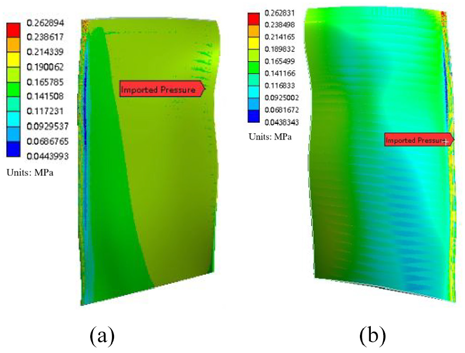
Mean aerodynamic load distribution on blade surface: (a) suction surface and (b) pressure surface.

The first three natural frequencies and mode shapes of the blade with no crack.

The natural frequencies and mode shapes of the blade with crack 1.
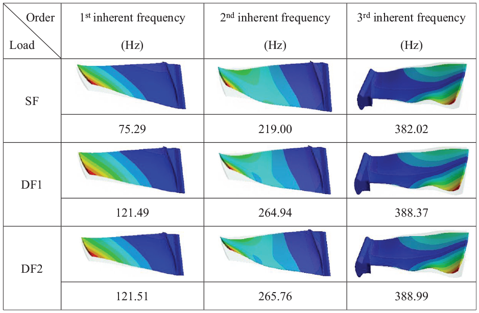
The natural frequencies and mode shapes of the blade with crack 2.

The natural frequencies and mode shapes of the blade with crack 3.
It can be seen from Figures 12 to 15 that with the increase of the load (SF → DF1 → DF2), the same order natural frequency of the blades under the same crack size increases, DF1 increases substantially compared to SF, the increased range is as follows, the increased range of 1st inherent frequency is in 61.24%–61.41%; 2nd inherent frequency (Second inherent frequency) is in 20.86%–21.13%; 3rd inherent frequency (Third inherent frequency) is in 1.63%–1.70%, and DF2 increases very little comparing to DF1, the increase range of 1st inherent frequency is only 0.02%–0.07%; 2nd inherent frequency is 0.31%–0.39%; 3rd inherent frequency is 0.08%–0.18%; when there is a transverse crack in the lower part of the blade back arc, as the crack increases (no crack → crack 1 → crack 2 → crack 3), the natural frequencies of the circumferential, axial bending vibration, and the torsional vibration of the blade decrease with the increase of the crack size. The reason for these characteristics is that both load and crack will affect the blade stiffness, which changes the natural frequency. Increasing the centrifugal load or decreasing the crack size will increase the blade stiffness, thus increasing the natural frequency of the blade; decreasing the centrifugal load or increasing the crack size will decrease the blade stiffness, accordingly decreasing the natural frequency.
Harmonic response analysis
The harmonic response analysis of the blade structure is carried out in this section. The natural frequency of the blade can be obtained by analyzing the steady-state vibrational response of the blade under the harmonic excitation. Based on the finite element model under consideration of the centrifugal load and aerodynamic mean load, the 5 N remote force is exerted on the blade, and the blades with different crack sizes are analyzed. The frequency-response curves of the leading edge point for the blades are extracted, as shown in Figure 16. The first three-order natural frequencies of the four configurations are roughly all 120, 265, and 390 Hz, respectively, which are approximately equal to the first three natural frequencies calculated by mode analysis. The existence of a difference is related to the setting of the step size for the harmonic response analysis. It can also be seen from Figure 16 that the amplitude of the first-order natural frequency is insensitive to the change of crack size, the maximum amplitude difference is only 12.02%; the amplitude of the second-order natural frequency increases with increasing of the crack size when the crack is extended from no crack to crack 3, the amplitude increases by 252.83%; the amplitude of the third order natural frequency decreases with increasing of the crack size when the crack is extended from no crack to crack 3, the amplitude is reduced by 97.80%. The local amplification of the frequency response curve is shown in Figure 17.
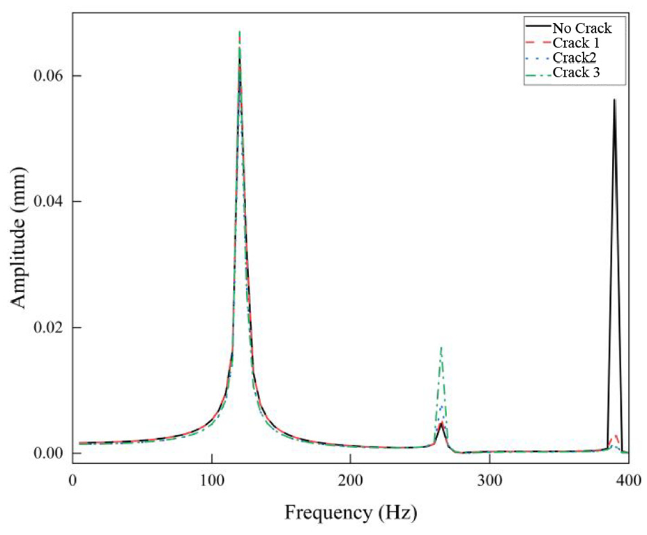
Frequency response curve of the leading edge point for the blade.

Local amplification of the frequency response curve: (a) first order, (b) second order, and (c) third order.
Determination of the structural damping
The vibration and life of blades are easily affected by the structural damping, and the structural damping is difficult to measure experimentally. Therefore, the appropriate structural damping of the blade will be determined by calculating the vibration amplitude of the blade and making the amplitude equal to the amplitude of the experiment. The experiment of the blade vibration was conducted, and the curve of vibration with change of time is shown in Figure 18, where the vibration amplitude is 0.80 mm. By adjusting the damping, the calculated amplitude (Figure 19) is equal to the experimental amplitude, thus, the reasonable damping ξ = 0.001 is determined. The subsequent vibration response calculation and life analysis are based on the damping value, this lays a solid foundation for the accurate calculation of vibration and life.

Vibration displacement diagram of the leading edge point for the blade with change of time obtained by experiment.

Vibration displacement diagram of the leading edge point for the blade with change of time obtained by FEA (Finite Element Analysis).
Static strength analysis
The static strength analysis of the blade is the basis of fatigue lifetime analysis. Static strength analysis is used to determine the strength characteristics of the structure under the static load. The centrifugal load of 3000 RPM and the mean aerodynamic load are applied to the blades with different crack sizes, and the static strength of the blades is analyzed. From the preliminary calculation results, it can be seen that the maximum stress of the blade is in the lower area of the blade body, so only the stress cloud map of the lower part of the blade body and the root of the blade is shown in Figure 20. It can be seen from Figure 20(a) that the maximum static stress of the blade without crack appears in the red circle, and the value is 549.78 MPa; the maximum static stress of the other three blades with the different crack sizes appears at both ends of the crack, the values are 666.90, 696.682, and 797.33 MPa, which increase by 21.30%, 26.75%, and 45.03% comparing with the crack-free blade, respectively. It can be deduced that under the action of the centrifugal and mean aerodynamic loads, the maximum static stress of the cracked blade appears at both ends of the crack, and the maximum static stress value increases with the increase of the crack size.

Static stress distribution diagram of the blade root: (a) no crack, (b) crack 1, (c) crack 2, and (d) crack 3.
Dynamic strength and fatigue lifetime calculation
The dynamic strength analysis should be conducted to obtain the dynamic stress curve of the key points of the blade before the fatigue lifetime analysis. The centrifugal load of 3000 RPM and the time-variable aerodynamic load are applied to the blade to calculate the dynamic stress curve of the key points of the blade. The position of the key point of the blade without a crack is at the blade root, and the position of the key point of the blade with a crack is at both ends of the crack and the dynamic stress curve of each key point is shown in Figure 21. The average stress and stress amplitude of each point can be calculated from the dynamic stress curve, the

Dynamic stress curves of the key points for the blades with the different crack sizes: (a) no crack, (b) crack 1, (c) crack 2, and (d) crack 3.
The
Comparison of the fatigue lifetime of the blades with the different cracks.

Conclusions
Cracks may occur in the dynamic blade of the gas turbine compressors during long-term operation and further expand to cause fractures. Aiming at this difficult problem, based on the transient dynamic analysis method, we consider the Rayleigh damping effect, centrifugal and time-varying aerodynamic loads, and a new method for calculating the vibration response and high-cycle fatigue life of cracked blades is proposed. In this paper, the influence of different crack sizes on the high-cycle fatigue life of the blade is studied. The main conclusions are summarized as follows.
(1) The effects of the loads and crack sizes on the first three natural frequencies of the blade are studied. The 1st order natural frequency of the blade under the centrifugal load increases greatly compared with the static frequency, and the 1st order natural frequency of the blade under the centrifugal and aerodynamic loads increases slightly compared with the frequency only considering the centrifugal load. When there is a transverse crack in the lower part of the blade back arc, the natural frequencies of the circumferential, axial bending vibration, and the torsional vibration of the blade decrease with the increase of the crack size.
(2) The small crack size has little effect on the first three natural frequencies. The modal transient dynamic analysis method is adopted to obtain the vibrational responses of the blade under the centrifugal and aerodynamic loads. The vibration displacement of the leading edge point of the blade is calculated, and the structural damping of the blade is determined after comparing it with the experimental data, so as to ensure the accuracy of the dynamic stress and fatigue lifetime calculation for the blade.
(3) The fatigue lifetime of the cracked blades is analyzed based on the Goodman curve and the S-N curve. The static strength analysis of the crack-free and cracked blades is carried out, and the maximum static stress value of the blade without crack is 549.78 MPa; the maximum static stress of the blades with the different crack sizes all appear at both ends of the corresponding crack, the stress increases with the increase of the crack size to a certain extent; the three stress values increase by 21.30%, 26.75%, and 45.03% compared with the crack-free blade, respectively. When the crack occurs in the blade and the crack size increases, the position of the maximum dynamic stress shifts from the blade root to the two ends of the crack, and the mean dynamic stress
(4) Limitations and Outlook. Although this study has reached several important conclusions regarding the dynamic response and fatigue lifetime evaluation of cracked blades, there are still factors not considered that may affect the comprehensiveness of the results. For instance, the nonlinear behavior of materials, the complexity of crack propagation, and the deformation and load variations under different operating conditions still require further experimental investigation and research validation. These factors may have significant impacts on the fatigue lifetime and safety assessment of blades in practical applications, and future research should focus on an in-depth exploration of these aspects.
Footnotes
Appendix
Handling Editor: Divyam Semwal
Funding
The author(s) disclosed receipt of the following financial support for the research, authorship, and/or publication of this article: This project is supported by National Natural Science Foundation of China (Grant No. 52275118).
Declaration of conflicting interests
The author(s) declared no potential conflicts of interest with respect to the research, authorship, and/or publication of this article.