
Abstract
High-speed heavy-load spiral bevel gears put forward high requirement for flexural strength; shot peening is a technique that greatly improves the bending fatigue strength of gears. During shot peening, a large number of fine pellets bombard the surface of the metal target material at very high speeds and let the target material undergo plastic deformation, at the same time strengthening layer is produced. Spiral bevel gear as the object of being bombarded inevitably brought the tooth surface micro-morphology changes. In this article, we aim to reveal the effect of microtopography of tooth shot peening on gear lubrication in spiral bevel gear, try to establish a reasonable description of the microscopic morphology for tooth surface by shot peening, to reveal the lubrication characteristics of spiral bevel gears after shot peening treatment based on the lubrication theory, and do comparative research on the surface lubrication characteristics of a variety of microstructures.
Introduction
Shot peening is used for precision gear drive widely. Lubrication characteristics become an increasingly significant issue for a gear drive by shot peening strengthening. Many scholars researched the lubrication and fatigue of gear transmission and also obtained some academic achievements. L Dimitrov et al. 1 investigated the contact fatigue resistance of gear teeth by experimentally and analytically subjected to shot peening treatment. L Guo et al. carried out a serial sectioning procedure on a shot-peened 12Cr martensitic stainless steel to determine the location of fatigue crack initiation sites from pits of varying depth. These results indicate that common assumptions about crack initiation from pits in shot-peened steel can be misleading. 2 S Li proposes a contact fatigue model for spur gears operating in high speed. A comparison between quasi-static life and tribo-dynamic is performed to demonstrate the important role in the fatigue damage. The impacts of the input torque, surface roughness and lubricant temperature on gear contact fatigue are also investigated. 3 C Zhou et al. established a new normal stiffness model for oil film, the viscous-elastic fluid between spur gear pair being equivalent to a massless spring element, and the tangential stiffness model is proposed according to the hypothesis of equal shear stress on laminar element surfaces. It is indicated that the rational parameter match is valid in mesh impact reduction and stationarity enhancement. 4 D Gallitelli et al. 5 proposed an approach that can reveal the relation between the state of treated part and process parameters. Y Lv et al. studied W6Mo5Cr4V2 steel gear tooth flank by laser irradiation, and then treated by shot peening with shot particles of different materials and peening time. The experimental results have showed that the hardness of gears increased and the surface roughness of gears decreased after shot peening treatment. In addition, the residual stress state in the near-surface layer of shot-peened gears was changed from tensile stress to compressive stress. 6 A Terrin analyzed six case hardened sun gears damaged by pitting during endurance tests. All analyzed gears belong to planetary final drives placed on a wheel hub of axles for off-highway vehicles. The aim of the analysis was to highlight the key aspects of the morphology and the evolution of pitting damage on the case hardened sun gears. 7 W Pu et al. 8 conducted an analysis in lubrication performance, friction and gearing geometry for spiral bevel and hypoid gears. C-B Tang et al. investigated the effect of plasma molybdenizing and shot peening on fretting wear and fretting fatigue behaviors of Ti6Al4V alloy. The results indicate that a beneficial residual compressive stress distribution, high surface hardness with suitable hardness gradient distribution, good apparent toughness, relatively low surface roughness, and excellent surface integrity are achieved. 9 B AlMangour presents an attempt at inducing grain refinements through a shot peening process creating severe plastic deformation at the outer surface layers to improve the physical properties of components produced by Direct Metal Laser Sintering (DMLS). The research result can highlight the efficiency and applicability of the shot peening treatment to practical cases. 10 The objective of this contribution is to analytically derive a solution of the Reynolds equation to describe the longitudinal fluid pressure distribution, load capacity, and coefficient of friction of a mechanical horsepower surface structure. It was shown that the lateral effects in machine hammer peened surface structures significantly increase the fluid pressure. Therefore, the analytical approach presented can be used to estimate the lower bound. 11 VV Simon 12 proposed a method that can minimize the influence of misalignments on lubrication characteristics of spiral bevel gears. S Mo researched the true tooth surface precise modeling method for spiral bevel gear in consideration of machining adjustment parameters and used the experiment to prove that the modeling method is right and precise. At the same time, the research in star gear transmission system was also conducted.13,14 IS Tertuliano studied the tribological response of four different advanced fully formulated gear oils and three different materials (coatings and topographies) in terms of friction and wear. He found that the frictional dependence on the surface topography and lubricant type is not significant, while the wear mechanisms were highly dependent on material and surface conditioning. 15 F Concli and C Gorla 16 introduced a new automated mesh-partitioning strategy implemented to extend the applicability of the previously developed computational effort reduction method to complex gearboxes getting over the geometrical limitations adopted in the past. S Haizuka 17 carried out a more fundamental research on tooth surface strength of gears with high hardness to increase the load-carrying capacity of gears. F Concli and C Gorla 18 proposed a comment on a review of the different available tools and described the characteristics of a single method for the availability of methods and tools to forecast the behavior with respect to lubrication and power losses. J Xie et al. analyzed the effect of shot peening on contact fatigue property in the aspects of bending fatigue of a single tooth, contact fatigue of tooth surface, contact fatigue crack initiation and propagation, the microhardness, residual austenite, residual compressive stress and substructure in surface layer. The results show that the residual compressive stress produced by shot peening and the phase change of microstructure caused by plastic deformation are main factors improving the contact fatigue strength of the gears. 19 W Welsch 20 conducted an in-depth study of controlled shot peening influencing the prestressing technique. F Concli 21 has developed an innovative calculation method capable to quantify efficiency and related operating temperatures under different operating conditions to find the best compromise between the load-carrying capacity and the maximum transmittable power due to thermal limitations.
These researches just focus on elastohydrodynamic lubrication or shot peening. But few literature about elastohydrodynamic lubrication characteristics focus on shot peening. In addition, some people even assume that shot peening has few effect on elastohydrodynamic lubrication characteristics. Heretofore, few study focus on lubrication characteristics of spiral bevel gear by shot peening strengthening. This article reveals the lubrication characteristics of spiral bevel gears after shot peening process, based on the elastohydrodynamic lubrication theory, making a comparative research of the tooth surface lubrication characteristics of various microscopic morphologies.
The microscopic morphology description of spiral bevel gear tooth
The surface by shot peening is different from the roughness of tooth surface by mechanical processing, and the roughness of tooth surface after shot peening strengthening presents some regularities. When the spiral bevel gear enters elastohydrodynamic lubrication stage, the lubricating oil film between the two contact tooth surfaces and the peak of the roughness of tooth surface morphology after shot peening strengthening is in the same order of microcosmic magnitude. The projectile materials used in shot peening mainly include ceramic, cast steel, glass, cast iron, and so on. The shape of the projectile is mainly spherical. Being made in spherical can prevent concentrated stress point which is produced when the angle of projectile bumps into the workpiece surface. The size of the projectile is different. The smallest diameter is 0.1 mm, and the biggest diameter can be up to 2 mm. The size and the material of projectile must to be chosen according to the strengthening requirements of the sprayed workpiece surface, the roughness and mechanical properties of workpiece surface. The sketch of the surface of workpiece hit by single projectile, as shown in Figure 1. Single projectile hits the structure of the workpiece, as shown in Figure 2.

The sketch of the surface of workpiece hit by single projectile.

Single projectile hits the structure of the workpiece.
After shot peening, the strengthening effect involves many factors, such as material properties of the sprayed workpiece, the distance between shot peening machine’s nozzle and the contact surface of workpiece, the incident angle and the impact speed of projectile, fraction of coverage, the types of materials, hardness, the time of shot peening, size, and other factors about shot peening. The process parameters that affect the shot peening are many, and the coupling mechanism between them is very complicated.
The model of multiple-projectiles polarization shot peening strengthening
Because high precision machined surface topography has been completely destroyed after shot peening strengthening, the peak of the tooth surface roughness which is formed by shot peening is higher than the roughness level of the tooth surface formed by grinding. The current shot peening finite element (FE) model is divided into multi-projectile model. Figure 3 is the coverage and modeling principle of shot blasting for nine-pellet model. Figure 4 is the FE model of shot blasting strengthening (nine-pellet model). As shown in Figures 3 and 4, in the nine-pellet model, there are four pills in the first layer, two pills in the second layer, two pills in the third layer, and one pills in the fourth layer.

The coverage and modeling principle of shot blasting (nine-pellet model).

The finite element model of shot blasting strengthening (nine-pellet model).
Based on the modeling principle of nine-pill granule model, this article established high precision three-dimensional (3D) four-layer 25-pill granule polarization shot peening strengthening simulation model. Figure 5 is the coverage and modeling principle of shot blasting for 25-pellet model. Figure 6 is the FE model of shot blasting strengthening (nine-pellet model). This model assumes that the projectile arranges according to some rules and offsets distribution. The projectiles according to the order, in turn, vertically impact the target material surface, reduce the blind spot area, and improve the coverage. Based on the polarization modeling method, the radius of the first layer projectile is R, the projectile center distance is 2R, the second layer is offset from the first layer in X direction by R, the third layer is offset from the first layer in Y direction by R, the fourth layer polarization distance in x and y directions is R, and size of the target material is 6R × 6R × 12R. As shown in Figures 5 and 6, in the 25-pellet model, there are 4 pills in the first layer, 12 pills in the second layer, 9 pills in the third layer, and 1 pills in the fourth layer.

The coverage and modeling principle of shot blasting (25-pellet model).

The finite element model of shot blasting strengthening (25-pellet model).
Random distribution is a better approximation of shot peening process. But the shot blasting area may overlap. There are many factors that influence the effect of shot blasting. In this article, we only need to obtain the surface morphology after shot blasting.
However, there is one precondition: the surface morphology of target material has been completely destroyed after the shot blasting, and the characteristics of machining roughness have been lost.
Coverage is an important factor in achieving this condition. In the reinforcement of shot blasting in the 25-pellet model, the pit rules formed by shot blasting are obvious and independent, and there is no mutual influence. Therefore, we can study the effect of pit on the lubrication characteristics of the slug flow separately.
The target material is made of high-performance gear steel: 16Cr3NiWMoVNbE, and the mechanical parameters are as follows: elastic modulus is 210 GPa, Poisson’s ratio is 0.3, density is 7800 kg/m3, initial yield stress is 800 MPa, hardening modulus is 1000 MPa, and the Coulomb friction coefficient is 0.2. Mechanical parameters of projectile are as follows: elastic modulus is 210 GPa, density is 7800 kg/m3, Poisson’s ratio is 0.3, and the initial velocity of shot peening is 50 m/s.
Among many nonlinear problems, contact problems are very common. Common contact problems can be summed up in two situations: rigid–flexible contact and semi-flexible–flexible contact. For this kind of metal forming process, scholars often regard this situation as rigid–flexible contact, in which the workpiece is regarded as flexible body and the mold as rigid body. In this article, rigid–flexible contact is adopted, in which projectile is regarded as rigid body and target material as soft body.
In this case, the initial velocity is set and the rotation of each projectile is limited, and the center of mass of the projectile is uniformly added to a velocity field in one direction, which simulates the process of projectile hitting the target material. The velocity of projectile is uniform and the impact is regular. The establishment of target material is a part of simulated gear. The default shot blasting at the bottom of the target material has no effect on the bottom, so all the degrees of freedom at all points at the bottom of target material are set to zero. Since this example is only part of the interception gear, the four sides are not actually the boundary. In this case, the normal lateral displacement of the side is set to 0 and the four sides are “fixed.”
In this case, the face–surface contact algorithm is chosen to define the contact between projectile and workpiece. Because the hardness of the projectile material is much higher than that of the workpiece, the surface of projectile is set as the main contact surface, while the surface of workpiece is from the contact surface. The coulomb friction model was used to describe the contact between projectile and workpiece. According to the practice of engineering and references, we set the friction coefficient as 0.2.
Some constitutive model can be used for shock problem, such as Cowper–Symonds constitutive model, Johnson–Cook constitutive model, and Zerilli–Armstrong constitutive model. According the speed of shot peening, we chose the Cowper–Symonds constitutive model. This model is suitable for the collision of high strain rate materials. The Cowper–Symonds constitutive model has considered the strain rate in the FE model.
The model of shot peening surface microstructure
The results of shot peening simulation and the microstructure of shot peening are shown in Figure 7. It is clear that the projectile and the target surface make a collision and all rebound, leaving a lot of regular craters on the surface of the target. Twenty-five-pill model did not completely change the microstructure of the tooth surface, between the crater and the crater, and there are many areas that projectiles do not cover.

The surface microtopography of target material by shot peening strengthening.
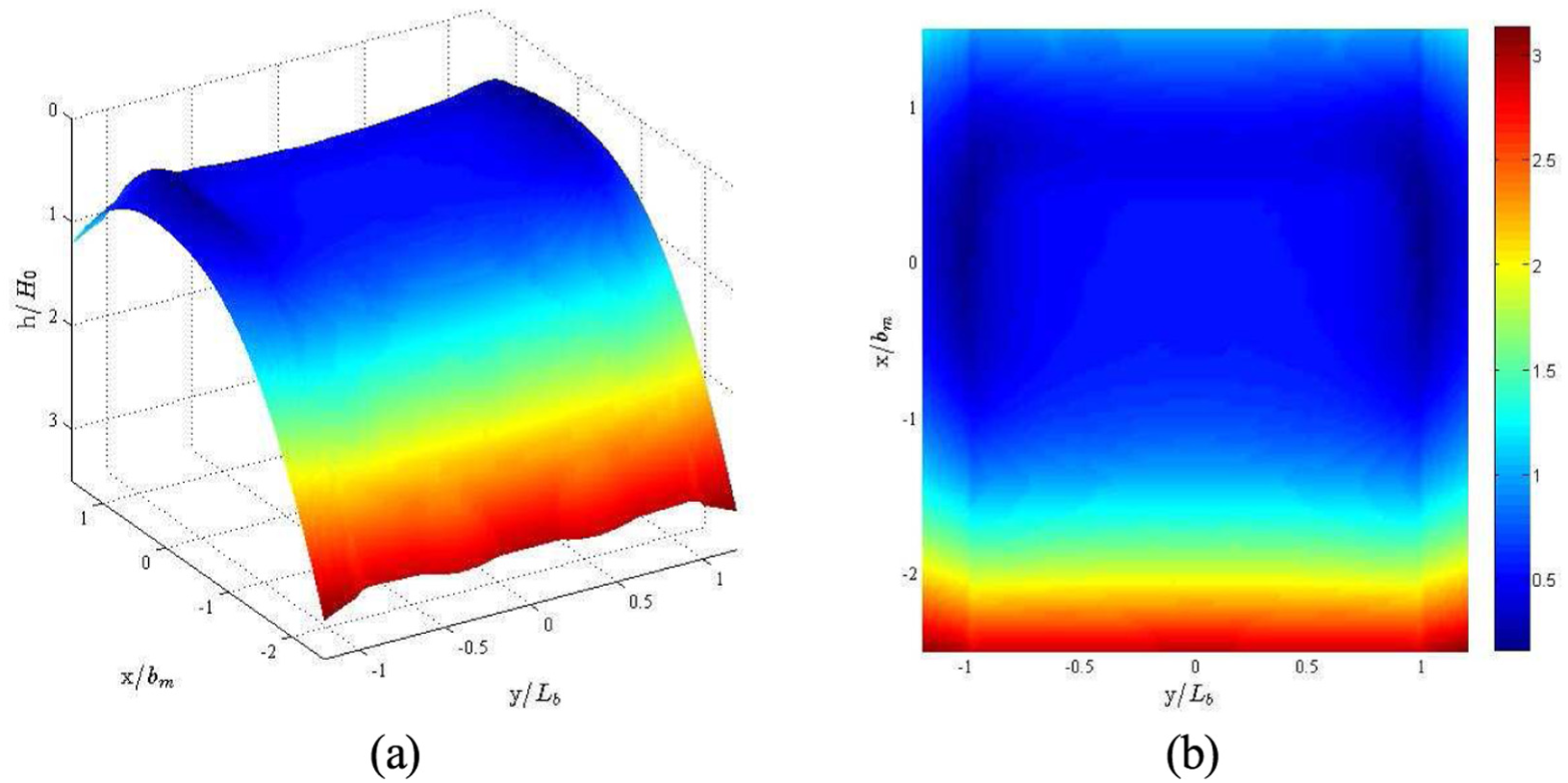
The numerical calculation of the lubrication characteristics is finally done in MATLAB, so it is necessary to realize the numerical representation and reconstruction of the surface after shot peening in FE simulation and convert the finite element analysis (FEA) model into numerical model, extract the deformation data of the shot peening surface, and derive the data to form the .txt file. The surface microtopographic data after shot peening were sorted by surface node number, forming a surface morphological database and importing into MATLAB. The 3D matrix of surface topography is established in MATLAB, the numerical simulation and reconstruction of surface morphology are carried out, and 3D cloud was formed, as shown in Figure 8, x axial is stand for the half-width of Hertz contact of gear pair, y axial is stand for the node at the location of the contact line half-length.

Reconstruction of surface topography by shot peening.
Equivalent lubrication model of spiral bevel gear
During meshing process of spiral bevel gears, the lubricating oil film between the two contact surfaces is at the same order of the roughness of the machined surface, local contact area rough contact will occur, and the gear will get into the mixed lubrication state. Lubricating oil film is subjected to strong shear which will produce non-Newtonian fluid properties. With the effect of limiting torque, the oil film thickness is drastically reduced or even ruptured, the metal surfaces contact directly, and the tooth surface enters the dry friction state. As one of the boundary conditions of the elastic fluid lubrication model, the load distribution determines the thickness of oil film and the magnitude of pressure in contact zone.
Equivalent gear model of spiral bevel gear
Starting from engineering practice, when the gear is not at very high speed, the steady-state load distribution model is applicable. To establish the numerical model of the long-chain contact steady-state mixed elastic-flow lubrication in the meshing area, it is necessary to master the classical Hertz contact theory and the elastic fluid lubrication theory to establish the film thickness and the Reynolds equation. Finally, both the distribution of pressure and film thickness will be solved, and the elastic-flow characteristics of shot peening gear will also be analyzed.
This article mainly explores lubrication characteristics of gear tooth surface after shot peening strengthening. Predecessors theory and experimental results have shown that although the tooth surface shape is complex of spiral bevel gear, as long as in the same operating conditions, the spiral bevel gear can be treated as the equivalent of cylindrical gear. Therefore, we can use classical elastic-flow theory.
Aiming at the problems of gear contact, it is necessary to establish a long-term contact two-dimensional elastic-flow lubrication equation. Take the suction speed of the contact point as the x-axis, the contact line direction as the y-axis, and the contact area normal direction as z-axis.
In view of this, the study model is based on the equivalent cylindrical gear system shown in Figure 9, and the gear transmission parameters are shown in Table 1. Lubricating oil parameters are as follows: viscosity coefficient α = 2.272 × 10⁻² mm/N and dynamic viscosity η0 = 5.4 × 10⁻⁸ N m/mm2.

The gears’ meshing equivalent system.
Parameters of gear drive.

Using cylindrical gear as the equivalent gear of spiral bevel gear, tooth number of equivalent cylindrical gear is called as equivalent teeth number of the spiral bevel gear. zv is the tooth number of equivalent cylindrical gear, z is the tooth number of spiral bevel gear, δ is the pitch angle of spiral bevel gear, and dv is the pitch diameter of equivalent cylindrical gear for spiral bevel gear. Based on the knowledge of mechanical principle, we can obtain zv = z/cosδ. So zv1 = z1/cosδ1, zv2 = z2/cosδ2, dv1 = mzv1, dv2 = mzv2. N1c and N2c are the radius of curvature for two contact cylinder in lubrication theory, N1c = dv1sinα, N2c = dv2sinα.
Lubrication control equation
S(x, y) is the roughness function of contact tooth surface for tooth surface a. This function can be described by either the random roughness function simulated in this article or the surface morphology after shot blasting. The basic equation of elastohydrodynamic lubrication is discretized with steady-state condition as an example. The average velocity in the y direction is small compared to that in the x-direction, so it can be ignored in calculation. For steady-state conditions, the extrusion term can be omitted.
For steady-state conditions, the gear pair at each meshing position is equivalent to a pair of reverse disk rollers with different radius of curvature, and the load of each roller is different. With steady load distribution as the elastohydrodynamic lubrication equation of boundary conditions, mesh position on the pitch circle of gear to numerical lubrication condition can obtain the moment of contact area pressure distribution and change the rule of oil film thickness. The elastohydrodynamic lubrication state of the meshing gear at this position is used to express the lubrication state of the whole area, and then the elastohydrodynamic lubrication characteristics of the shotcrete gear can be calculated and solved.
The following hypothetical conditions are quoted in the research work. The fluid in the lubricating film is a continuous medium. The inertia force and volume force in the fluid differ by several orders of magnitude from the surface force, which is ignored in this article. Because the lubricating oil film is particularly thin, it can be regarded as the constant fluid pressure, viscosity, and density in the direction of thick oil film. As the lubricating oil film is particularly thin and the tangential velocity of the fluid surface is much higher than the normal velocity, except, other velocity gradient in the fluid is removed. The lubricating oil film and the metal friction surface adjacent to it have stable adsorption and no relative sliding.
Reynolds equation and boundary conditions
Figure 10 is the deformation of Hertz contact area. Non-Newtonian fluid refers to a fluid that does not satisfy Newton’s law of viscosity, that is, its shear stress and shear strain rate are not linear relations. Under the condition of elastohydrodynamic lubrication, a variety of additives is added to the lubricant, and the lubricant would normally work under high pressure and high shear resilience. In the small contact area, lubricating oil film will bear local high pressure momentarily. Obviously, under such high pressure, shear stress and temperature rise will result in severe non-Newtonian properties of the lubricant. In terms of description of rheological model, Ree–Eyring model, J-T model, and B-W model are generally accepted.

The deformation of Hertz contact area.
The non-Newtonian fluid is chosen as the lubricant, and the Reynolds equation suitable for unsteady line contact is presented below

In formula (1), p and h are the pressure and oil film thickness, η* is the equivalent viscosity of the lubricating oil, ρ is the density of the lubricating oil, t is the time variable, μx is the tooth surface suction velocity, and it is the average of the sum of the tangential velocities, we can also say μx = (μa + μb)/2.
Equation (1) is actually a flow balance equation from the physical point of view. The first term on the left end of the equation is the pressure flow along the x-direction in the fluid lubricating oil film due to the pressure gradient, also known as the Poiseuille stream. The first term on the right indicates the shear flow due to the surface velocity, also known as the Couette flow, and the second term of the right end is the change in the flow rate caused by the squeezing motion, including the change in density.
The boundary condition of formula (1) is as follows
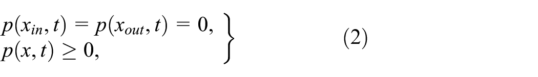
In the formula, xin is the starting point of the calculation area coordinates, and this article takes xin = −4b; b is the Hertz contact half-width; xout is the end of the calculation domain coordinates, and this value cannot be artificially set, only in the numerical calculation process to determine by iterative.
Oil film thickness equation
Figure 11 is the geometric gap of equivalent cylindrical. In the case of elastic fluid lubrication, the contact deformation of the cylindrical surface in the normal direction can affect the shape of the gap. Under the effect of load in contact zone, the normal direction of the two cylindrical surfaces is deformed elastically, and this deformation is manifested as surface depression. Assume the tooth surface a is a rough surface and the tooth surface b is a smooth surface, when the elastic cylindrical contact, the thickness between the engagement tooth film is as follows


Geometric gap of equivalent cylindrical
In formula (3), h0 is a constant associated with the thickness of the rigid body membrane, and it is also the thickness of the rigid body; Δh =x2/2R is the amount of change in film thickness as the tooth profile changes toward the x-direction. R is the combined curvature radius of the meshing point and E′ represents the elastic modulus of teeth. S(x, y) is the function of contact surface for the tooth surface A, and this function can be a random roughness function or one of the surface morphologies after shot peening.
Load balance equation
In the absence of external force, the contact area of the two reverse cylinders is a line, but when the external force is applied on the load in the direction of generatrix, the contact line will be extended to a contact area, and the oil film which is squeezed creates a pressure distribution in contact area. The balancing equation of load can be written as follows

In equation (4), A is the total area of contact area, Cw is the load coefficient, and wn is the load of each pair of meshing instantaneous target teeth. In steady state, Cwwn = Fs.
Rheological model of lubricating oil
In the event of elastic fluid lubrication, lubricants usually bear high pressure and high shear strain force, and in a small contact area, the lubricating oil film will occur instantaneously at local high pressure. Obviously, such a high pressure, shear strain, and temperature rise will cause the oil to exhibit severe non-Newtonian properties. The description of the rheological model is generally accepted with the Ree–Eyring model, the J-T model, and the B-W model.
At present, the Ree–Eyring model is used as the rheological model of lubricants in the elastic fluid lubrication model and is applied to the unified Reynolds equation

In equation (5), τ0 is the reference shear stress,
Lubricating oil viscosity η uses Roelands relation

In equation (6), z is the viscosity index, and η0 is the environmental viscosity of lubricating oil. The equivalent viscosity η* satisfies the following equation

The lubricating oil density ρ uses the Dowson–Higginson formula

In equation (8), ρ0 is the initial density.
Dimensionless equations
Generally before the analysis of the operation, it is necessary to take the parameters of each basic equation to do dimensionless processing. In order to make the number of variables in the dimensionless equation smaller, making the computational machinery of the equation easier and easier to simplify the process. The article selected the commonly used non-quantifiable parameters

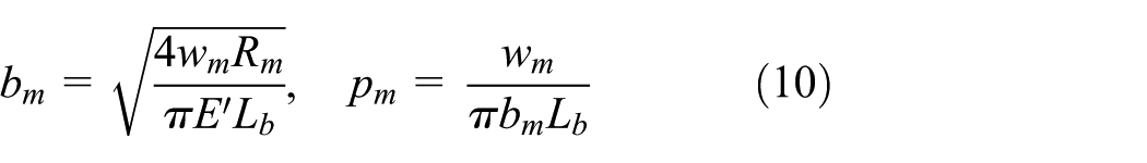
In the formula, ρ0 and η0, respectively, are the environmental density of the oil and the environmental viscosity; Lb is the node at the location of the contact line half-length; Rm and μm, respectively, are the node at the integrated radius of curvature and the suction speed, and the node position under the load of Hertz contact area, half-width and peak pressure, is expressed as follows
Substituting equations (9) and (10) into equations (1)–(4), we obtain the dimensionless elastic-flow control equation.
where R is the integrated radius of curvature for two contact surfaces, and relationship between the radius of curvature R1 and R2 of the surface l and surface 2 is as follows

E′ is the integrated elastic modulus of two solid materials surface, the elastic modulus E1 and E2 of the solid l and solid 2, and Poisson’s ratio is as follows

Calculation flow chart
The Reynolds equation is solved by iterative method, and each cycle uses two convergence criteria to determine whether to continue the loop or to be out of the cycle, output pressure, and film thickness values, as in equation (13)

Figure 12 provides a flow chart for solving the two-dimensional finite-length contact steady-state mixed elastic fluid lubrication calculation.
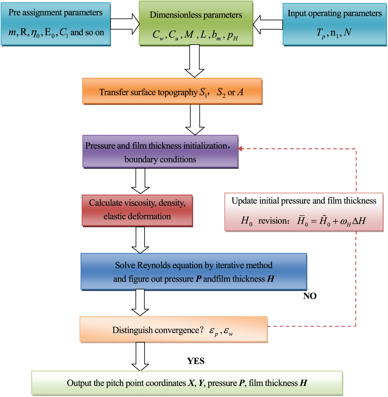
Flow chart of elastohydrodynamic lubrication.
Lubrication characteristics of gear-pressure distribution and oil film thickness
Performing the elastic-flow analysis to multi-pellet bias, shot peening model can better observe the impact of a single crater on the lubrication and research the effect of shot peening on elastohydrodynamic lubrication after remodeling the entire micro-surface. Figures 13 and 14 show the 3D distribution of elastic pressure and oil film thickness after shot peening, x axial is stand for the half-width of Hertz contact of gear pair, y axial is stand for the node at the location of the contact line half-length, h axial is stand for the film thickness of oil, p axial is stand for the pressure of oil. It can be known in Figures 13 and 14 that the overall match the three rules of pressure and film for the distribution.
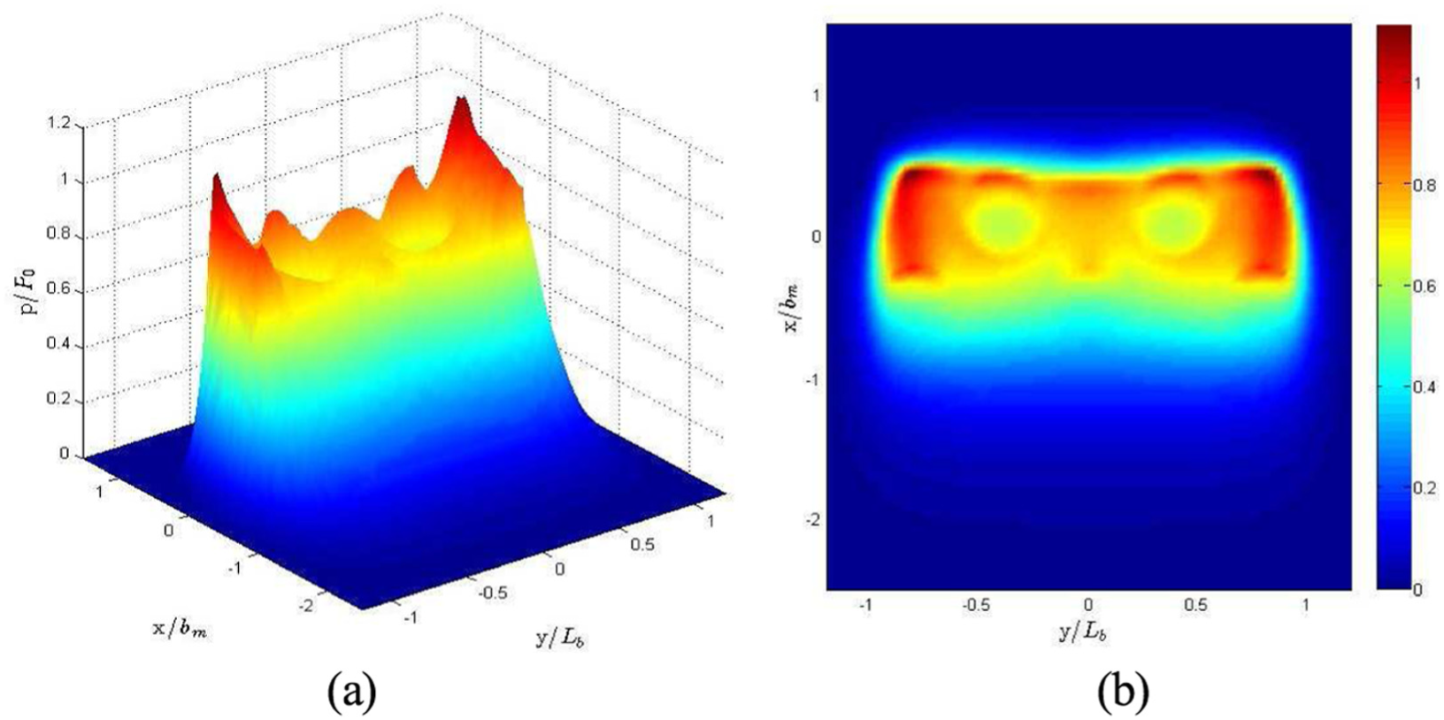
Distribution of lubrication pressure.
Distribution of oil film thickness.
Along the direction of the meshing line, with the increase in load, pressure gradually increases, oil film thickness decreases gradually, the two end faces of contact area will appear at the peak in pressure area due to the concentration of stress, and it can reach P0∼1.15P0. A certain degree of reduction will happen to the corresponding film thickness of both sides, only 0.4H0∼0.6H0, the pressure presents a low distribution between the two highs, and the thickness just at the opposite.
In the direction of the take-up speed, x began to play elastic lubrication from a contact area half-width bm, the load determines the size of the peak pressure on a large program, but the place of the largest the pressure is not in the center contact area. As the volume increases, there will appear the secondary peak in the exit area, but the area of the biggest pressure often is in the exit zone. The pressure of the inlet and the central zone is between 0.6P0 and 0.8P0, while the pressure of the outlet zone can reach P0∼1.15P0. Correspond to the distribution of pressure, the film thicknesses in the outlet area and the pressure peak area at both ends are the smallest. In the center contact area, due to the existence of deformation, the thickness of oil film is small and is about 0.6H0, away from the contact area, the lubrication changes from the elastic-flow state into a full film lubrication, and the oil film becomes bigger.
In the two end areas of exit area, the effects of the two are superimposed on each other, the largest pressure area occurs, the pressure can reach the maximum of 1.15P0. The thickness of oil film is less affected by the take-up speed, the smallest thickness of oil film appears in the contact area on both sides, the minimum is only 0.4H0. In general, the pressure and the thickness distribution of the elastic fluid lubrication are affected by the load and the take-up speed.
Observing at the same time, it can be concluded that the local pressure will drop at the pits formed by the shot peening, the film thickness will rise, and the effect will be obvious. Puffed tooth surface orange peel pits contain more oil, which is conducive to lubrication, while in the bumps formed around the orange pits, the pressure increases and the influence is greater in the direction of the take-up speed, and the pressure peaks are easily to be formed.
Figure 15(a) is the distribution of film thickness (y = 0.5 section), Figure 15(b) is the distribution of pressure (y = 0.5 section), Figure 16(a) is the distribution of film thickness (x = 0 section), and Figure 16(b) is the distribution of pressure (x = 0 section). In Figures 15 and 16, the distribution of pressure and oil film thickness at y = 0.5 and x = 0 are given. The section of y = 0.5 is just across the orange peel pits, the section of x = 0 is also just across two orange peel pits. Along the x-direction, the pressure is concentrated in Hertz contact area, pressure value is forward, and there is a secondary peak. The pressure in the central area pits decreased significantly from 0.75P0 to 0.6P0. The pressure is reduced by 20%, while the pressure of this part should be increased. The thickness of oil film in central area is about 0.6H0, in the export area it reaches the minimum, 0.45H0.

Distribution of pressure and film thickness (y = 0.5 section).

Distribution of pressure and film thickness (x = 0 section).
Leaving the contact line areas, the film thickness increases to the positive and negative directions. Along the y direction, the pressure of the both ends is higher than the pressure of central area, and there is a pressure peak. The pressure in the pit is significantly reduced from 0.75P0 to 0.6P0. The pressure is reduced by 20%, but the pressure of this part should not be too small, and the pressure around the pit should not be too big. The thickness of the film in the central area is small and basically the same in the 0.5H0 up and down, and there is a phenomenon of increased thickness of the pit, which is 0.55H0. Under the influence of pressure on both ends, the thickness of the film decreases by a minimum of 0.2H0.
Conclusion
It can be concluded that for the orange peel pits, it is no doubt that the occurrence of pits enlarges the gap between the gears, the pressure at the pit decreases significantly and can reduce more than 20%. At the same time, the thickness of the film at the pits increases, although the magnitude of the increase is not large, and it can increase the lubricating oil here.
On the contrary, due to the emergence of pits, protrusions form around the pits, and these protrusions greatly increased the pressure, because of the increasing of the pressure, the deformation is also enlarged, finally the change of thickness for oil film is very small. The appearance of the protrusion around the pits is not conducive to lubrication, easily give rise to excessive pressure, and finally oil film ruptures.
Footnotes
Appendix 1
Acknowledgements
The authors acknowledge Prof. Haruo Houjoh and Shigeki Matsumura of Tokyo Institute of Technology, Prof. Izhak Bucher of Israel Institute of Technology, Prof. Yidu Zhang of Beihang University, and Mr Zhou Yao and Ms Wei Hong for their constant assistances.
Handling Editor: Michal Kuciej
Declaration of conflicting interests
The author(s) declared no potential conflicts of interest with respect to the research, authorship, and/or publication of this article.
Funding
The author(s) disclosed receipt of the following financial support for the research, authorship, and/or publication of this article: This research is supported by Natural Science Foundation of Tianjin (No. 17JCQNJC04300), Open Funding of the State Key Laboratory of Materials Processing and Die & Mold Technology-Huazhong University of Science and Technology (No. P2019-022), Open Funding of The State Key Laboratory of Mechanical Transmissions (No. SKLMT-KFKT-201616), Applied Basic Research Project of China Textile Industry Association (No. J201806), Fundamental Research Funds for the Tianjin Universities (Nos 2017KJ083, TJPUZK20170118), National Natural Science Foundation of China (Nos 51475330, U1733108), and the Program for Innovative Research Team in University of Tianjin (No. TD13-5037).