
Abstract
This study presents a novel optimal controller that is designed based on a linear transformation with upper and lower prescribed functions. The utilization of the linear transformation, akin to the Kalman function, forms an integral part of the optimal control input. The development of the proposed controller is rooted in non-conventional prescribed techniques, which contribute to its uniqueness and innovative nature. The effectiveness of the proposed controllers is assessed by applying them to regulate the vibration of a suspension system featuring a semi-active magnetorheological fluid base damper (MR Damper in short). Initially, random peaks representing random disturbances are employed as excitations in the simulation and two benchmark controllers (conventional optimal control and linear matrix inequality (LMI) control which has been modified to have conventional upper and lower boundaries) are carefully selected for reasonable comparison. The simulation results unequivocally demonstrate that the proposed controller possesses stronger capabilities in suppressing vibrations when compared to the benchmark controllers. The controllers are also applied in the real suspension system. The experimental results show that the proposed control provides better than the comparative controllers with around 18% and 35% reduction for the seat displacement and the seat acceleration, respectively.
Keywords
Introduction
The modern control with its features of optimal control and prescribed performance is still developing with new forms and frequently requires significant advancement with extensive applications in both industries and household devices. The study by Chen and Braun 1 presented an optimal technique that utilized a model-based forward prediction and an adaptive model using Hessian and Cholesky factorizations to design a linear transformation. The objective of this proposed approach was to minimize the time lag between the simulation progress on the computer and the real-time progress during system control. In Chen et al., 2 the findings from Chen and Braun 1 were expanded by integrating a switching-type model, and the adaptation laws were based on the input control function and the switching time function. However, the control efficiency of the proposed approach was affected due to the high number of iteration steps required by the inequality switching model. A new modification of the Bolza-Meyer criterion, which relates to the cost function of optimal control, has been proposed in Phu et al. 3 Two gain matrix functions were designed based on the state variables and the input control function. As demonstrated in Do et al., 4 the performance of optimal control was improved by utilizing adaptation laws in which both the disturbance boundary and PID control were taken. This model employed the Riccati-like equation for both the state matrix and disturbance matrix, followed by the application of a switching function to optimize the calculation progress. The control design often encounters two challenges: time delay and dead zone. These issues were successfully addressed by employing a modified optimal control approach utilizing the Riccati-like equation, as demonstrated in Phu and Mien. 5 The methodology presented in Phu and Mien 5 introduced a novel concept for resolving the closed boundary of the dead-zone phenomenon in structures incorporating smart materials. The concept of prescribed performance can be incorporated into the sliding surface of sliding mode control and combined with optimal control, as demonstrated in Do et al. 6 The proposed control approach in Do et al. 6 showcased its robust performance in the presence of significant disturbances. The modification of the H-infinity technique was investigated in Bergeling et al., 7 where a novel input control approach for optimal control was introduced. This approach was involved for minimizing the argument of the state variables to address the bottleneck frequency in a network system. A comprehensive analysis of the quadratic nonlinear system was provided in Sassano and Astolfi, 8 where the models were formulated based on the Hamiltonian function, incorporating new definitions of the virtual disturbance function on the initial boundaries. The research direction of iterative optimal control for online updates was outlined in Chen and Braun. 9 It is worth noting that the controller presented in Chen and Braun 9 shares similarities with the studies conducted in Chen and Braun 1 and Chen et al. 2 Typically, the feed-forward optimal control is regarded as a crucial aspect of control system design. However, a fresh perspective on feedback optimal control was introduced by Zhu. 10 This model employed the Hamilton-Jacobi-Bellman equation as the primary approach for deriving the proposed control. To facilitate the determination of boundaries in optimal control, the analysis of a novel symplectic algorithm was conducted in Chen and Zhu. 11 These tools presented in Chen and Zhu 11 served as essential mathematical models for obtaining both theoretical and experimental state variables of the system. A recent advancement in prescribed performance was introduced in Katsoukis and Rovithakis. 12 One notable distinction between the conventional model of prescribed performance and the model proposed in Katsoukis and Rovithakis 12 lies in the flexibility of adjustable response areas during control action.
Recently, the implementation of prescribed performance within specified timeframes has been further explored through various applications.13–26 The traditional prescribed performance approach was initially utilized by Li et al. 13 In this study, the prescribed tracking time was determined by delineating the boundaries through a t-norm formulation of the state variables. Furthermore, a backstepping technique was introduced to formulate the controller. It is worth noting that the time component in the prescribed time model typically incorporates a time-varying function, often designed based on an exponential-like function. This methodology was also adopted by Wang et al. 14 in conjunction with the traditional prescribed performance framework. Moreover, the conventional prescribed performance was leveraged to enhance adaptive control based on a fuzzy model, as demonstrated by Ding et al. 15 The backstepping approach was similarly employed in this model. Additionally, a time-varying function following an exponential pattern was utilized to anticipate the prescribed time for adaptive control in the study by Zhang et al. 16 The application aimed to address the limitations of fault-tolerant control by integrating prescribed performance and time-varying functions, as highlighted in the research by Liu et al. 17 Notably, the signum function was incorporated into the leader controller, designed using conventional optimal control techniques. In scenarios requiring control in unknown directions, prescribed performance with Nussbaum-like equations was employed, as explored by Aforozi and Rovithakis. 18 In the aforementioned analyses, a consistent methodology involving the combined use of prescribed performance, prescribed-time models, and time-varying functions was implemented in studies conducted by Xu et al., 19 Wan and Zeng, 21 Zhang and Xiang, 23 Singh et al., 24 and Stihi et al. 26 The challenge of delayed time in control applications was addressed through prescribed forms in research by Yilmaz and Krstic, 20 Adil et al., 22 and Ding et al. 25 These studies introduced novel approaches to managing delayed time, utilizing techniques such as gradient and Hessian, 20 linear matrix inequality (LMI) methods, 22 and the signum function. 25 Optimal control and sliding mode control methodologies were also explored in the designs as evidenced by Zhang and Xiang, 23 Singh et al., 24 and Stihi et al. 26
Based on the above analysis, the Hamiltonian equation emerges as the principal model for optimal control, making it a key equation in enhancing the performance of new optimal control techniques. The exploration of diversified optimal control approaches has been conducted3,4,13,16 to achieve robust performance in the presence of severe disturbance. The introduction of diverse algorithms has facilitated flexible calculations. Furthermore, the establishment of response boundaries has been also based on the concept prescribed performance.16,26 However, the conventional models of prescribed performance have fixed boundaries that follow user-defined models. In higher levels, the conventional prescribed performance combined with the time-varying model for obtaining the optimal time in controlling has been recently presented in several works.13–26 However, the disadvantage of these studies are continuously to use the conventional model of the prescribed technique with no breakthrough in the design, besides of the time-varying function. This problem can be seen as a milestone in the development of the modern control related to the prescribed technique. Therefore, this study introduces a proposed model that utilizes new linear transformations of the Kalman function, incorporating new definitions of both upper and lower boundaries following the optimal-like control and the prescribed technique. The aim of this proposed model is to overcome the disadvantageous properties of the current models mentioned above and validate the effectiveness of the proposed controller by applying it to vibration control of the vehicle seat suspension system incorporating a magnetorheological fluid-based damper (MR damper). The boundaries are derived from a novel non-conventional prescribed performance approach. In summary, this study offers several key technical contributions in controller design and vibration control application. Firstly, the theorem of a new optimal control with the upper and lower functions is proposed. Secondly, simulations of the proposed control and two benchmark controllers are analyzed to show the excellent properties of the proposed controller. Thirdly, three controls are carried out in the real seat suspension system to validate its eminent properties.
This article is organized as follows. In Section “Design of proposed flexible prescribed optimal control,” the proposed control is derived and proved its stability. In Section “Application to magneto-rheological fluid suspension system and discussions,” the application to seat suspension system is experimentally carried out and subsequently discussed the results achieved from both simulation and experiment. Finally, Section “Conclusion” briefly concludes the main result done in this work with comments on the future works.
Design of proposed flexible prescribed optimal control
The proposed control is designed following nonlinear model, which is default in any system. The governing equation of a nonlinear system is defined as follows:

Where,

Where,
In this proposed model, the values

Where,
The t-norm forms using in equation (3) guarantee the positive value and the tracking performance in case of trajectory application. In case of using in vibration control, the value of t-norms in equation (3) can play as corresponding boundary through the upper and lower values to guarantee the performance in reducing the vibration. The terms


Equation (4) can be alternatively expressed in the following form:
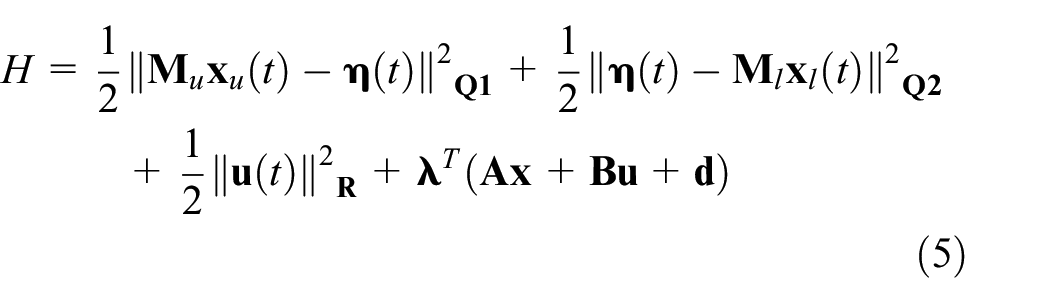
Where,


In equation (13), the value

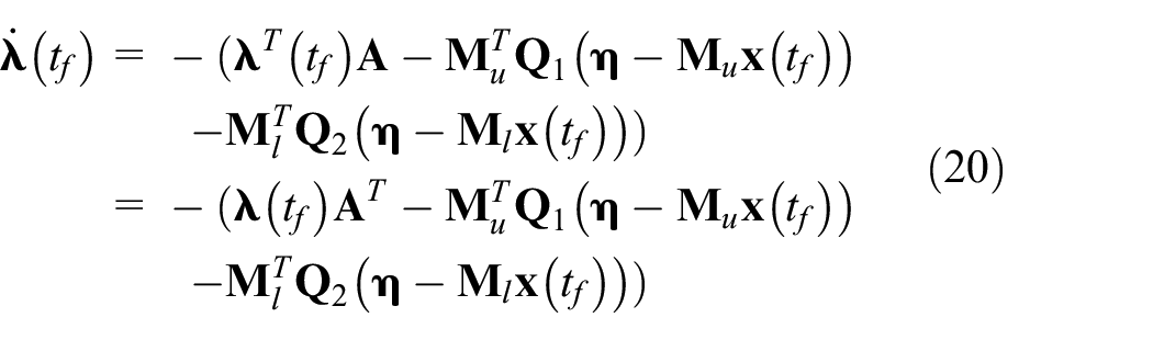
On the other hand, the co-state dynamic equation or Euler-Lagrange equation (5) is given by

The result equation (15) can be expressed as follows:


By utilizing equations (14) and (16), the result can be written as follows:

The optimal input control is given by:

By substituting equation (18) into equation (17), we obtains:
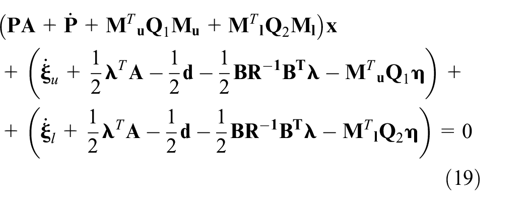
Using equation (14), we obtain three equations as shown in equations (8)–(10). The proof of equations (8)–(10) is now complete. ■
Now, let’s proceed with the proof of conditions equations (11) and (12). By solving equations (8)–(10), the dynamic parameters of the system, as shown in equation (2), are determined, and subsequently find the input control equation (18). This progress ensures the stability requirement and good performance of the controlled system. Utilizing equation (16) for the final time
By solving

Where,
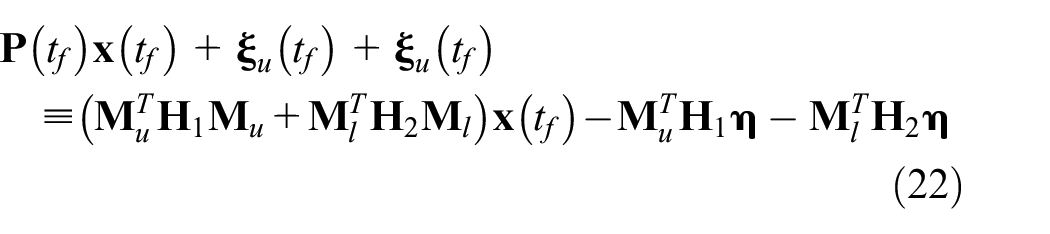
Applying the homogeneity coefficient method to equation (22), the values of


The boundaries of

with the system
Where,


By utilizing equations (24) and (25), the performance function equation (26) is derived by employing the local variation approach as:

subject to


Where,


The boundaries of

Where,
By utilizing equations (32)–(35), the results of equations (32) and (33) can be obtained in the following forms:


The results equations (34) and (35) indeed represent the maximum boundaries of the local variation of


Where,
The progress of calculating proposed control is summarized in Figure 1. The dynamic outputs of the system serve as inputs to the conditions presented in equations (11) and (12) and the adaptive optimal laws (8)–(10). The output of the adaptive laws is then utilized to determine the value of the control input, as shown in equations (2) and (18). In the subsequent stage, the input control is applied to control the plant. During the calculation progress, the output values of the observer are utilized to evaluate the performance of the plant’s output.

Flow chart of the proposed control.
Application to magneto-rheological fluid suspension system and discussions
Magneto-rheological fluid suspension model
In this study, the vehicle seat suspension system with a MRF damper, as investigated in Do et al. 6 is utilized to showcase the efficacy of the proposed controller. This model is different from the seat models in Yang et al. 27 (active suspension system), Turan et al. 28 (negative stiffness structure), and Maciejewski et al. 29 (active seat suspension). The main characteristic of the MR suspension is semi-active model based on the feature of MR damper. The application of the proposed controller in the MR model helps to observer the variation of the responses through the input control and other parameters explicitly. It is noted that the MR damper with its controls was also presented in Pang et al. 30 and Wu et al. 31 These models can be seen as the second potential choice for evaluation test.
The mechanical model of the MR suspension system is depicted in Figure 2. The governing equations of the system are derived as follows:

Where,


MRF seat suspension model.
It is observed that

The detailed dynamic values of the system are presented in Table 1.
Values of MR seat suspension system.

The damping force

Where,


Values of MR damper. 30

In these equations (43) and (44), the values of
Simulation: Experiment results and discussions
The simulation is conducted based on the mathematical models proposed in Theorem. The essential parameters of the theorem utilized for setting up the simulation are presented in Tables 1 to 5. Additionally, two benchmark models from Chen and Braun 1 (Compared control 1) and Do et al. 4 (Compared control 2) are selected to compare their properties and results with the model derived from Theorem. The model by Chen and Braun 1 represents the conventional optimal control, while the control by Do et al. 4 is a new modification of the prescribed performance with the conventional upper and lower boundaries employing the linear matrix inequality (LMI) method. These selected models are the optimal choice for assessing the accuracy of the proposed control compared to the existing controls of Chen and Braun 1 and Do et al. 4 To analyze the performance of the proposed control and benchmark controls in Chen and Braun 1 and Do et al., 4 we apply an initial excitation with random peaks as shown in Figure 3. The simulation results, depicted in Figures 4 to 6, showcase various aspects such as displacement-time, upper boundary function – time, lower boundary function – time, conventional prescribed performance – time of the second comparative control. Figure 4(a) highlights the exceptional vibration control properties of the proposed control, compared to the comparative controls illustrated in in Figure 4(b). As mentioned earlier, the proposed control introduces a novel flexible prescribed performance, which adheres to the upper boundary function and the lower boundary function outlined in the Theorem equations (9)–(12). These aspects are illustrated in Figure 5(a) and (b) for the upper and the lower boundary functions, respectively. In Figure 5(a), the upper calculated boundary highlights that the obtained values consistently belong to the established functions associated with the upper and lower functions, as indicated in equations (9) and (11). Despite fluctuations in the final stages of the control progression, the upper boundary values consistently remain below the prescribed boundaries. This variation is also from the strong disturbance applied in this simulation with the objective to evaluate performance of the proposed control. Similarly, the lower boundary values in equations (10) and (12), as depicted in Figure 5(b), fall within the range of the upper and lower boundaries. It also exist the variation in the end of the lower boundary, which is also mentioned as shown in the upper boundary function (9) and (11). These results substantiate the effectiveness of the newly proposed model in control, as demonstrated in Figure 4, showcasing a breakthrough flexible prescribed performance. The results presented in Figure 6(a) and (b) for the second comparative control further validate the aforementioned observation: the conventional prescribed performance exhibits lower efficiency in controlling severe continuous disturbances. This also proved that the conventional prescribed performance cannot follow the fast variation of the severe disturbance, and then its calculation is low than expected in this environment. These results prove that the proposed models stand outs significantly compared to the others. These results severe as evidence that the proposed model, incorporating the new Kalman function (2) and its adaptation laws, as depicted in equations (8)–(12), effectively handle severe disturbances. The application of the upper and lower boundary functions allows for flexible calculations in the face of disturbance variations.
Definition of parameters of the proposed control.

Definition of parameters of the Compared Control 1. 1

Definition of parameters of the Compared Control 2. 4


Random excitation for simulation.

Simulation result of displacement-time of the proposed control and two compared controls: (a) general view and (b) large view.

Boundary function of the proposed control: (a) upper function and (b) lower function.

Conventional prescribed performance of the second comparative control: (a) general view and (b) large view.
From the above results, the proposed control and the second comparative control (compared control 2) are chosen for carrying out the experimental test. It is noteworthy that these controls are the same method in implementation of the prescribed-like performance in design. The final results are shown in the next section.
Experimental results and discussions
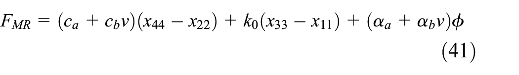
As mentioned above, two controller such as the proposed control and the compared control 2 with both theirs best performance and theirs model in simulation are chosen for experimental test. The setup equipment system are shown in Figure 7. The sensors using for the test include a linear variable differential transformer sensor (name: Honeywell, type: JEC-AG-DC-DC) for the displacement of the seat, an acceleration sensor (name: CLX Xbow MEMSIC, type: IMU440) for the acceleration of the mass (human), an acceleration sensor (name: Crossbow, type: CXL04M1Z) for the acceleration under the seat. There are two dSpace DS1104 boxes for controlling and collecting the signals from the sensors and the vibration table. The dSpace systems are protected by setting up the maximal voltage 10 V. It is noted that the damping force from the MR damper is 1000 N at an input current 2 A. The applied voltage to the MR damper is calculated following equations (41) and (42). It is noted that the vibration table in this experiment has frequency 0.3 Hz, which is suitable for evaluation the suspension. Hence, the proposed experiment for controls is limited in this frequency for safety requirements for both human and machines.
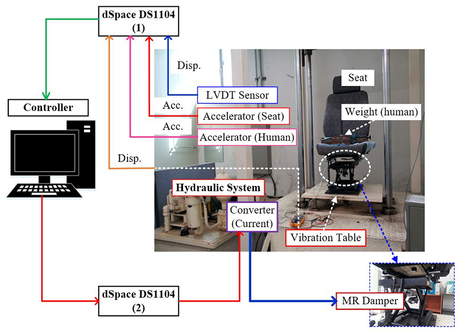
Experimental system with suspension featuring MR damper.
The flow chart of the experiment is shown in Figure 7. The bump signal is used for this test with a peak as shown in Figure 8. This signal is differ from the simulation, which using the random signal with multiple peaks. The bump test gives an ideal evaluation with any controllers in severe disturbance and guarantee the safety for the machine in the test. The displacement of the seat in the experiment is depicted in Figure 9(a). It is shown that the proposed control has good performance, which is better than the others. The initial peaks in the excitation are controlled well, and replaced by the new peaks, which is less than the initial values. The new replacement of peaks is appear in three controllers. The ranges of the seat displacement in Figure 9(b) are

Experimental vibration.

Experiment result of seat: (a) general view of displacement and (b) large view of displacement.

Experiment result of seat: (a) general view of acceleration and (b) large view of acceleration.

Experiment result of human (driver): (a) general view of acceleration and (b) large view of acceleration.

Experiment result of applied current.
From the above analysis, the proposed controller is always better than the compared controls. It can be improved performance based on the special mechanism in design with flexible boundaries following the variation of the system inputs. The statistical values of the controls associated to the seat displacement are approximately 61%, 59%, and 77% for the compared control 1, the compared control 2, and the proposed control, respectively. The difference value of the proposed control is around 18% when comparing with the comparative controls, which can be seen a good value for using this control in real application. When evaluating following the peaks of the seat acceleration, the proposed control has the best index approximately 35% comparing with the other controls. These indexes show that the proposed control can be adapted with the prompt response in severe disturbance.
Conclusion
This study presented an innovative approach to formulate a controller featuring a flexible prescribed performance by modifying the Kalman function. This model can give a breakthrough of the conventional control model considering the prescribed performance. The proposed model was derived using a non-conventional linear transformation of Kalman function incorporated with embedded upper and lower boundary functions. All variables of the linear transformations were updated following three adaptation laws to account for disturbances where the stability of the proposed controller was analyzed and proven based on maximal values of boundaries. Following the formulation, simulations were conducted to compare the performance of the proposed model with two existing benchmark controllers presented by Chen and Braun 1 (compared control 1) and Do et al. 4 (compared control 2). The simulation results demonstrate that the proposed control performs admirably under severe continuous disturbances and surpasses the performance of the compared controllers. To validate the performance of the proposed control in real application, the MR seat suspension system was used and tested experimentally by implementing the proposed controller. Three controllers including the proposed model, the compared control 1, and the compared control 2 were realized in a closed-loop control test. The experimental results show that the proposed control is better performance compared with two bench marked controllers in all dynamic state values. It has been quantitatively identified that the proposed controller can reduce vibration higher 18% and 35% than compared controller 1 and 2, respectively, in terms of displacement and acceleration. This result directly indicates that the proposed controller derived using a non-conventional linear transformation of Kalman function incorporated with embedded upper and lower boundary functions can provide a strong foundation for the potential application in real systems, particularly those characterized by uncertainty and severe disturbances. It is finally remarked that this study will be applied to the exoskeleton model in the future to improve the tracking performance. In addition, the model of prescribed time will be derived as future works.
Footnotes
Appendix
Handling Editor: Sharmili Pandian
Funding
The author(s) disclosed receipt of the following financial support for the research, authorship, and/or publication of this article: This research is funded by the Ministry of Education and Training Vietnam (MOET) under grant number B2024-VGU-02.
Declaration of conflicting interests
The author(s) declared no potential conflicts of interest with respect to the research, authorship, and/or publication of this article.