
Abstract
In order to reduce vibration and increase ride comfort, this article utilizes a system of quarter-car suspension integrated with a Fuzzy PID controller. To build and improve the Fuzzy PID controller for the semi-active suspension system used in quarter cars, using a novel meta-heuristic technique known as Grey Wolf Optimizer (GWO). Here the magnetorheological damper (MR) fluid with the Fuzzy PID controller was examined to optimize using the GWO algorithm. With the GWO technique and the integral of time absolute error (IAE) as a fitness function, the three gain parameters of the Fuzzy PID controller – Kp, Ki, and Kd– have been optimally set. The suggested approach has additional advantages for the optimization of functions with three variables, including simplicity in implementation, quick convergence traits, and superior computational capabilities. This work is significant, to the best of the author’s knowledge there is no optimization method using GWO to online tune a Fuzzy PID controller for a semi-active suspension system. The optimal output parameters of the controller can be updated online in real-time by GWO. The performance of the proposed controller was examined by assessing the root mean square (RMS) values and peak-to-peak (PTP) values of body displacement and body acceleration under various road profiles. To ensure that the intelligent controller was of the highest caliber, an online test rig was constructed. Results from simulations and online experiments demonstrated that the Fuzzy GWO PID controller significantly improved ride comfort under a variety of road conditions when compared to the Fuzzy PID controller and passive suspension system.
Keywords
Introduction
Vibration control utilizing MR dampers has been covered extensively in published references. A variable damper and appropriate control mechanisms are critical for semi-active vibration control. Research 1 used the MR fluids to develop an adjustable damper, and mechanical characteristics including damping constant and reaction time were assessed. The time delay of the damper should be taken into account while designing controllers because the reaction time of the MR damper was significantly greater than the nominal MR fluid response time. It has been demonstrated that the improved on/off vibration control, which incorporates the damper time delay, outperforms the traditional one.
The dampening effect of electromagnetic dampers is produced by the interaction of a coil’s motion with the magnetic field of an electromagnet or permanent magnet. 2
Semi-active suspensions were initially discussed in the literature 3 as a substitute for expensive, intricate, and power-dense active systems. Numerous studies on controlled suspension systems have been published in technical and scientific journals. Aljarbouh and Fayaz 4 conducted one of the studies on the current state of controlled suspensions in semi-active suspensions and other active suspensions.
Semi-active suspension systems offer superior road holding in addition to a more comfortable and controlled ride for the vehicle. These systems have the capacity to adjust the damping in reaction to monitored indicators of Vehicle handling and ride. To increase the vehicle’s stability and ride-handling capabilities, efforts for research and development have been conducted in a semi-active suspension.5–9
Today, PID controllers are used in every sector of the control industry, accounting for about 95% of all control loops. To get the most performance out of the system, three control parameters exist for the PID controller that is heavily dependent on one another for the response of the control loop. For systems having nonlinearity and restrictions, traditional controllers might not deliver the expected performance. 10 In contrast, fuzzy logic controllers (FLCs) can deal with nonlinearity and uncertainty while improving the attainment of PID structure. 11 However, there is no definite mathematical procedure to determine the best selection of fuzzy parameters (such as scaling factors, inputs, rule base, membership functions, etc.). These parameters are often chosen using a set of empirical rules, thus they might not be the best ones. Depending on the right choice of the optimization algorithm used for tuning the parameters, improperly choosing the input-output scaling factor may have an impact on the performance of optimal controllers. 12
The grey wolf optimizer, a novel optimization approach (GWO) is used for a variety of optimization projects with varied objectives. It has quickly drawn significant research interest from a variety of fields due to its quick programmability feature, comprehensibility, and high flexibility 13 as well as the fact that it deals with fewer algorithm parameters. By keeping the search process’s exploration and exploitation stages in balance, the GWO’s performance can be improved. The leadership ladder is mimicked by four different groups of grey wolves in the original GWO, called alpha (α), beta (β), delta (δ), and omega (ω). When calculating the updated position of the wolves across the iterations, the alpha, beta, and delta wolves are all given the same weight.
The Grey Wolf Optimizer (GWO) algorithm, a state-of-the-art optimization technique, is employed in this work to enhance riding comfort by optimizing the scaling factors of a Fuzzy PID controller for a semi-active suspension system on a quarter-car. By adjusting the external resistance or the magnetic field’s intensity, the damping level can be changed. The proposed Fuzzy GWO PID controller’s superiority has been proven under various road profiles by comparing the simulation and experiment results for the same semi-active suspension system with the fuzzy PID controller.
According to a literature analysis, the kind and proper design of the controller have a significant impact on the performance and stability of any plant that needs to be managed. A critical review of the literature finds that no articles have addressed the online 2-DOF-Fuzzy-GWO-PID controller-implemented system of semi-active suspension for quarter cars. In order to create a online 2-DOF Fuzzy PID controller with the best possible efficiency, this research work focuses on the development of the GWO approach. The study’s primary contributions are as described in the following:
Implementation of the Grey Wolf Optimizer approach to semi-active suspension systems.
Created a test bench to evaluate a quarter-car semi-active suspension system’s controller.
Online optimal design of grey wolf optimizer-based Fuzzy PID controller.
Demonstrate the superior performance of the Fuzzy PID controller optimized by GWO algorithm under various road profiles by comparing with a passive system and Fuzzy PID controller.
Grey wolf optimizer
A recently created metaheuristic algorithm called the “grey wolf optimizer” (GWO) models how wolves swarm hunt. 14 Grey wolf packs’ social awareness in terms of hunting and leadership served as an inspiration for the GWO algorithm. Each wolf pack has a fairly rigid social hierarchy. The top three characters in GWO are referred to as wolves: α wolf, β wolf, and δ wolf. The remaining characters are also referred to as ω wolves.
Hunting in groups is another fascinating aspect of grey wolves’ social behavior, in additionally to their social order. The key stages of grey wolf hunting are described by 15 like this:
(1) Locating, gaining ground on the prey, and pursuing it.
(2) The target is pursued, surrounded, and harassed till it comes to a stop.
(3) Going after the prey.
Surrounding prey
When hunting, grey wolves encircle their victim, as was previously indicated. To quantitatively model encircling behavior, the subsequent equations are suggested:
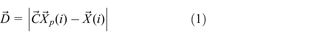

Where
Calculations for the vectors


in which parts of

where
A location vector in two dimensions and a few of the potential neighbors are shown in Figure 2 to demonstrate the implications of equations (1) and (2). In the point of X(i), a grey wolf can modify its location in accordance with the location of the prey Xp, as shown in this picture. By changing the values of the
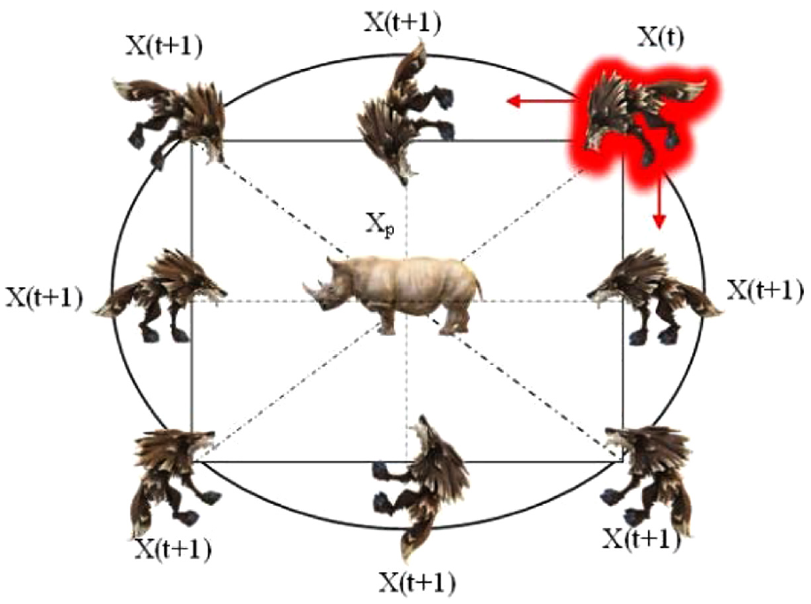
2D position vectors and potential future locations.
Hunt
Grey wolves have the capacity to locate their prey and surround them. Typically, the alpha leads the hunt. Hunting may occasionally be done by the beta and delta. However, in a generalized search environment, we are unsure of where the optimal is (prey). To mathematically mimic the way that grey wolves hunt, we suppose that the beta, delta, and alpha have more knowledge about the likely location of the prey. Because of this, we keep the top three results we’ve found up to this point and order all other searchers, such as the omegas, to realign themselves to match the top search agents’ placements. The formulas listed below are recommended in this regard.


In reaction to alpha, beta, and delta in a 2D search space, a search agent adjusts its position as shown in Figure 2. As is evident, The ultimate position would appear to be at random inside of a circle that is established by the positions of alpha, beta, and delta in the search space. So, alpha, beta, and delta determine where the prey is while the remaining wolves revise their locations haphazardly close to it.

Position updating in GWO.
Development of an intelligent controller for the quarter car suspension system
Suspension system for quarter car
This study employs a 2-DOF semi-active suspension system. Figure 3 16 depicts a schematic representation of the quarter vehicle model.

Quarter car model. 16
Where,
Mu stands for the unsprung mass, which consists of the mass of the wheels and related parts;
Ms stands for “sprung mass,” or “vertical mass with passenger”;
Zs represents displacement vertically of the sprung mass;
Zu represents the unsprung mass’ vertical displacement;
Zr is a measure of the road disturbance’s displacement;
Ks is the constant of the suspension spring;
Kt represents the tire’s spring constant;
Cs stands for constant damping;
Fa represents the MR damper’s dampening force;
The second rule of motion by Newton can be used to construct the following equations, which represent the two-degree-of-freedom system:

Where,
After choosing state variables as,


Disturbance caused by road roughbess,

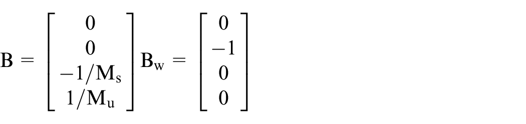
From equation (9), state space equation of the system is equivalent to form

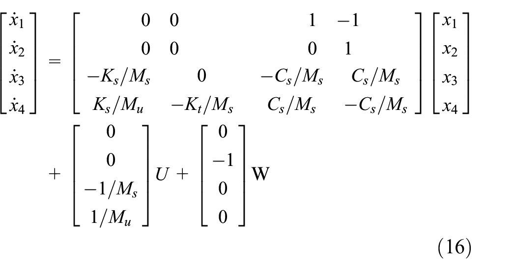
Where,


Magnetorheological damper model
This study employs the Modified Bouc-Wen Model. 17 MR damper is a hydraulic cylinder which consists of a piston, a magnetic coil and MR fliud. Figure 4 displays the schematic for the Modified Bouc-Wen Model. The model simulates the damper’s dynamic properties by using a variety of springs and dashpots.

Modified Bouc-Wen model. 17
Where,
kD 1 is invariant value of the accumulator stiffness;
cD 0 is the high-speed damping;
cD 1 is the damping applied to a dashpot to imitate the hysteresis loop at low frequencies;
kD 0 is a constant used to regulate stiffness for high velocities;
x 0 is the initial displacement due to the accumulator stiffness;
y is inner displacement;
xD is a damper displacement;
fa is the MR damper force;
The equations of the Modified Bouc-Wen model can be derived as follows. 17 For given input signals voltage and damper displacement, the output damping force can be predicted by the following equations:

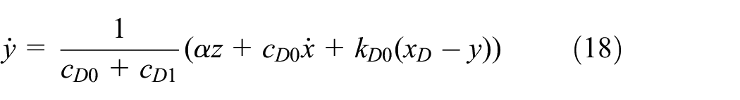


z is a parameter for assessment in equation (19). The voltage that is used in equation (20) is determined by the current driver.
η is u filter time constant. The parameters including
Road disturbance
Since the goal of this study is to enhance how well the suspension system is performing under various road circumstances, sinusoidal and random settings for the road profile were adopted, much like those used by researchers looking at the suspension performances of quarter cars.19,20
Signal waves with amplitudes of 6, 8, and 10 cm and a frequency of 2 Hz were used to simulate the sinusoidal road profile in Figure 5. Figure 6 shows how pseudo-random binary sequence (PRBS) MATLAB code was used to create the random road profile.
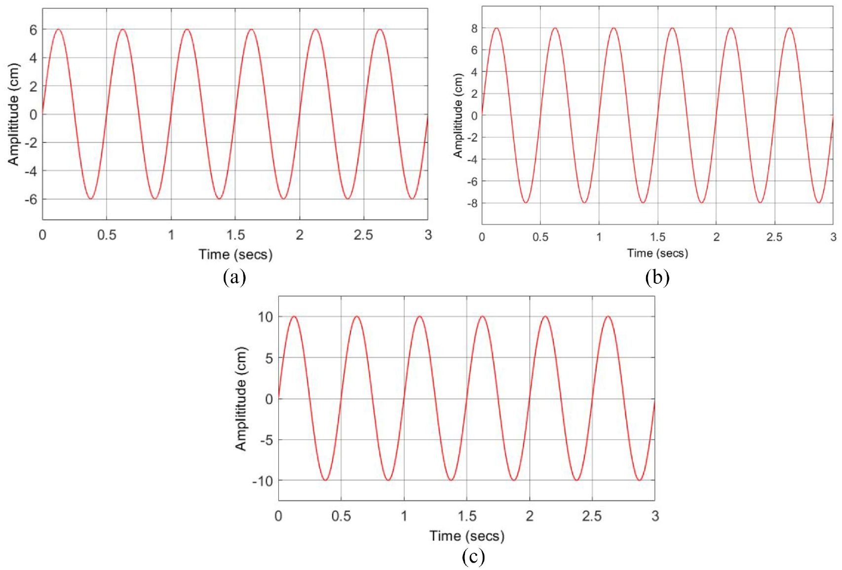
Sinusoidal road profile at (a) 6 cm, (b) 8 cm, and (c) 10 cm amplitude.
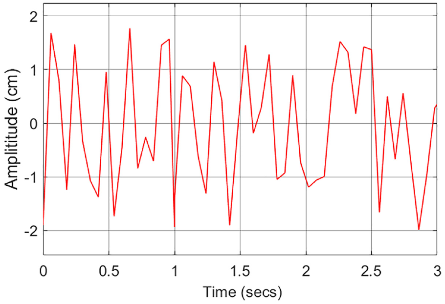
Random road profile.
Controller design
Design of Fuzzy PID controller
A fuzzy logic controller is used to modify the three control parameters (Kp, Ki, and Kd) of a Fuzzy PID controller, making it a unique type of PID controller. 21 A non-linear system with unpredictable parameter fluctuations cannot be tuned using conventional tuning techniques for a PID controller. 22 It is therefore required to simultaneously modify these parameters. Nevertheless, since FLC takes into account the system’s errors and uncertainties during processing, it might be possible to find a solution for figuring out the PID controller’s control parameters for a nonlinear system. 23 Figure 7 depicts a Fuzzy PID controller’s fundamental architecture. Two inputs are used in fuzzy logic controllers: the error signal and the rate of change of the error signal. Kp, Ki, and Kd are the FLC’s outputs, and they are sent to a PID controller.

Block schematic of Fuzzy PID controller. 24
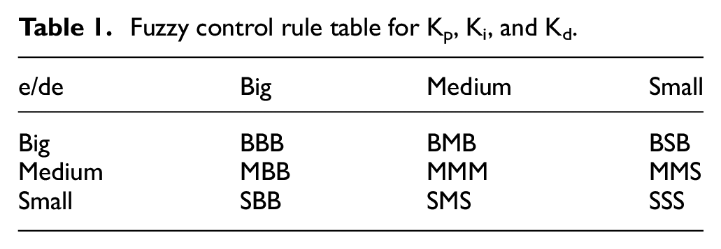
The triangular membership design for e and de is as follows: the error e and its derivative are both divided into three groups: Big (B), Medium (M), and Small (S). According to the Gaussian membership design, the Kp, Ki, and Kd output of the fuzzy logic inference system are similarly divided into the three states of Big (B), Medium (M), and Small (S). 25 Each output PID parameter has 3 × 3 = 9 rules, as indicated in Table 1, depending on the number of fuzzy variables in the input-output fuzzy sets.
Fuzzy control rule table for Kp, Ki, and Kd.
Design of Fuzzy GWO PID controller
The conventional Fuzzy PID controller is supported by the original GWO optimization algorithm in the construction of the suggested Fuzzy GWO PID controller simulation model, which improves the performance of the Fuzzy PID controller. The Kp, Ki, and Kd gains for the PID controller are the output of the fuzzy algorithm in the traditional way of the Fuzzy PID simulation model. This method is used to automatically tune the PID controller, but it is unsuitable for inconsistent changes that occur while operating the vehicle in various types of road conditions. Figure 8 shows the block diagram for the Fuzzy GWO PID controller. By feeding the PID with the GWO optimization’s most optimal parameters, it will be more effective at managing the behavior of the MR damper.

Block schematic of a Fuzzy GWO PID controller.
In this study, the social hierarchies and hunting strategies of the GWO are adapted. The most important component of the GWO optimization algorithm is that the gains of the PID controller are given to the best individual wolf’s location with the smallest fitness (Integral Absolute Error (IAE)). There are 30 search agents, and the GWO optimization’s dimension is set to 3 to reflect PID gains. Table 2 lists the GWO’s parameters. 25
Selected parameters and operators used in the GWO optimizer.

Simulation and analysis
Simulation model
Utilizing Matlab/Simulink, the simulation model is implemented (Mathworks, R2022a, Massachusetts, USA). Three suspension model testing procedures are tested concurrently in Figure 9 by the simulation. First up is the suggested Fuzzy GWO PID model, followed by the traditional Fuzzy PID model and finally the passive suspension model. Therefore, after utilizing the optimized model, the results will assess how well these suspension models performed and will highlight any instances of progress.

Comparation between different controllers for quarter car suspension system.
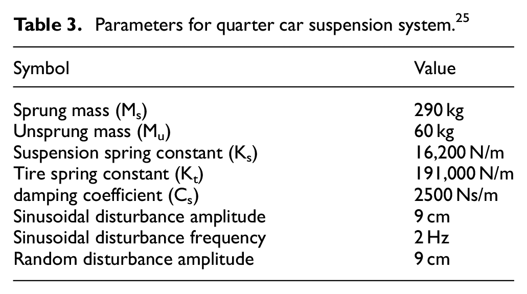
Table 3 is a list of the suspension system’s specifications. 25 Table 4 lists the modified Bouc-Wen model’s parameters. The suggested GWO algorithm would compare the suspension system error with the best GWO findings every time in order to aid in forecasting the best PID settings.
Parameters for quarter car suspension system. 25
Parameters for modified Bouc-Wen model. 17

Analysis
The RMS values of body acceleration (BAC) and body displacement (BD) are thought to be crucial performance factors that specify the unique ride comfort of the vehicle when assessing the ride comfort of the quarter-car type. After implementing the suggested Fuzzy GWO PID controller, Fuzzy PID controller, and passive suspension system, suspension response was obtained. Using the Matlab R2022a program, the results were graphed and examined in the time domain. As demonstrated in Figure 10, the proposed Fuzzy GWO PID outperformed the Fuzzy PID controller and passive system in the time domain when controlling the deflection behavior at three distinct sinusoidal amplitudes (6, 8, and 10 cm). The passive suspension system and Fuzzy PID controller, which are depicted by solid green and solid red lines, respectively, are taller. The solid black Fuzzy GWO PID controller has the lowest peak (lowest height).

The Fuzzy GWO PID, the fuzzy PID, and the passive system employing sinusoidal disturbance’s time responses to the suspension displacement at: (a), (b) 6 cm, (c), (d) 8 cm, (e), (f) 10 cm.
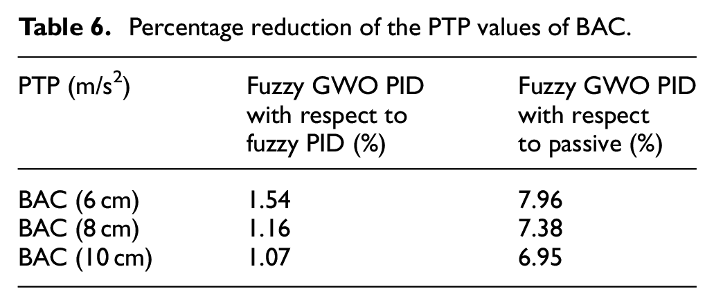
Figure 11 compares the peak-to-peak (PTP) values of the regulated semi-active suspension system utilizing the Fuzzy GWO PID controller, Fuzzy PID controller, and passive suspension systems. Tables 5 and 6 display their pertinent percentage improvement values. These findings make it clear that the semi-active vehicle suspension system managed by the Fuzzy GWO PID controller performs better. Out of all the suspension systems taken into consideration in this study, it offers the best ride comfort response. It’s crucial to understand that the Fuzzy PID controller and Fuzzy GWO PID controller use the same membership criteria and fuzzy design.
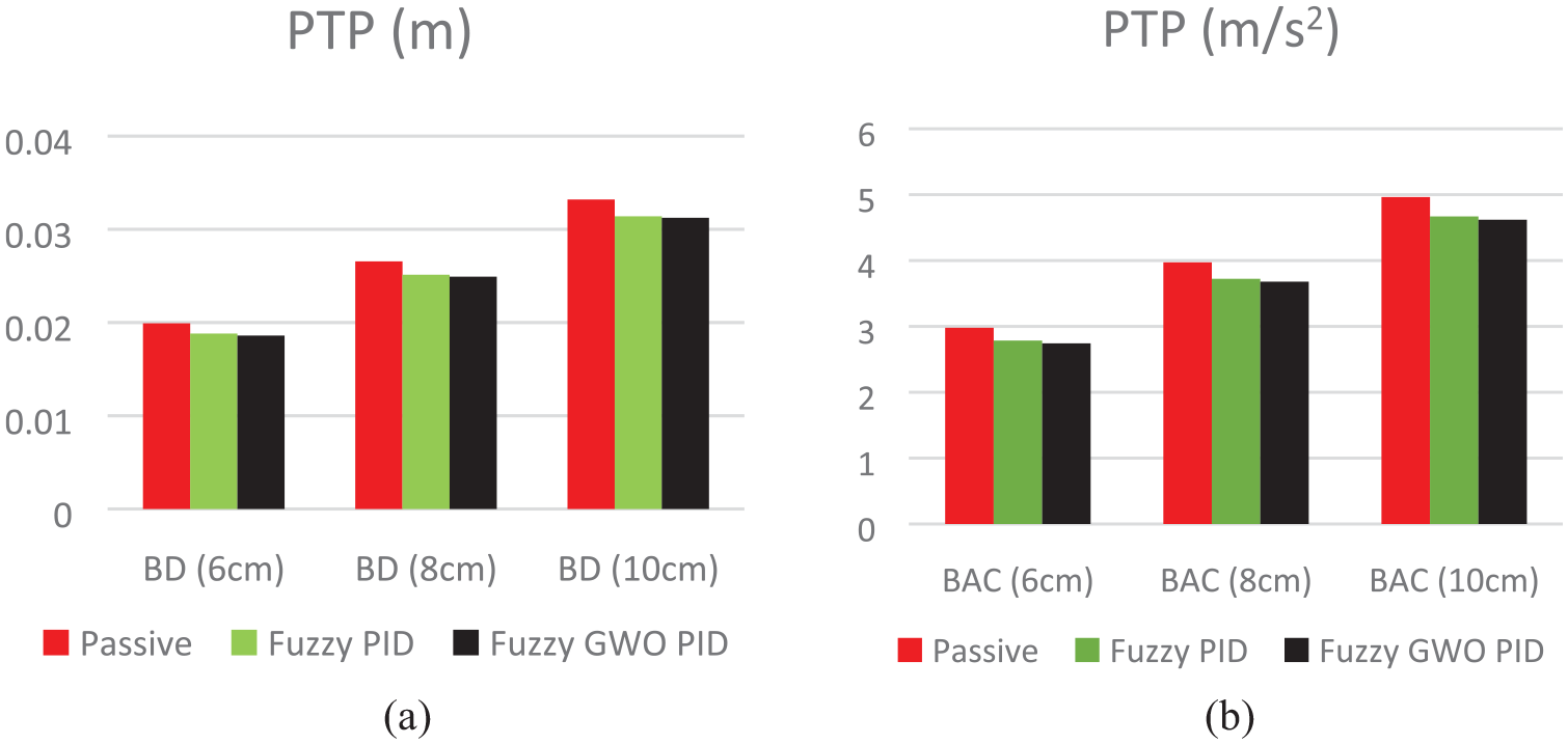
The PTP values of DB (a) and BAC (b).
Percentage reduction of the PTP values of BD.

Percentage reduction of the PTP values of BAC.
The recommended controller’s advantage in handling random disturbance is further demonstrated by Figure 12 and Table 7. For the semi-active suspension system controlled by Fuzzy GWO PID, Fuzzy PID controllers, and passive suspension system, the appropriate root mean square (RMS) values and PTP values are compared with those found. The findings are provided in Table 7, where the PTP values BD reduced by 2.39% and 6.52%, respectively, and RMS values BD reduced by 5.33% and 13.28%. Table 7 reveals that the Fuzzy GWO PID controller performs better than the competition on the whole.

The Fuzzy GWO PID, the Fuzzy PID, and the passive system employing Random disturbance’s time responses to the suspension displacement.
Percentage reduction of the values of BD.

Experimental set-up and analysis
Test rig
The components of the experiment employed in this investigation include one wheel with a tyre pressure of 40 psi (2.7 bar), springs with a stiffness of 15,000 N/m, MR dampers with damping coefficients ranging from 418 N/s/m to 673 N/m, and a carriage for transporting load. Table 8 provides the details of the test rig.
Parameters of the test rig. 25

As illustrated in Figure 13, the test setup for the quarter car suspension system uses a shaker that consists of a plate that can move up and down vertically with the help of a pneumatic cylinder. A three-two-way solenoid electric valve is utilized to control the movement of the cylinder and create the necessary road disruption in response to signals derived from LabVIEW code. The NI-SCC68 connection block, which the LabVIEW utilizes to provide control signals to it, is also used by the LabVIEW to obtain the test rig body’s and each tire’s most recent acceleration data using accelerometer sensors. The linear displacement sensor of the LVDT, which connects to the MR damper, was also used to read the vertical movement of the damper.

Quarter car suspension system test rig: (a) experimental set up and (b) electrical equipments.
The Lord Corporation’s RD-8041-1 MR damper was the damper utilized in this experiment. The damper has a 248 mm overall length and a 42.1 mm body diameter. Table 9 provides more information on the MR damper specs.
Parameters of lord MR damper. 25

Since it is made of the same material as the spring used in Anand Raj et al., 26 for support of the body, the experiment’s spring is connected to an MR damper and is predicted to be 20,750 N/m stiff. 635 N/m was the calculated damping coefficient for the sprung component.
Labview code
The program that controls the MR damper and reads sensor data was created using LabVIEW from NI. The code includes the primary interface display for Changing the experiment’s parameters and keeping track of the results gathered from the experimental test rig. Four loops are present in the LabVIEW code reading the test rig’s sensor data for acceleration and displacement takes place in the first loop, which serves as the primary loop. The GWO optimization algorithm is used in the second loop. The control loop is the third loop. There are Fuzzy PID controller and Fuzzy GWO PID controller in it. The fourth loop, which comes last, contains routines for various disturbance techniques.
Analysis
According to Figure 14 in contrast to the Fuzzy PID controller and the passive suspension system, the online Fuzzy GWO PID controller significantly reduced the suspension travel responses for 6, 8, and 10 cm sinusoidal road profiles. The online Fuzzy GWO PID controller’s peak amplitudes are clearly the lowest in peak value based on the frequency response, which clarifies how the designed controller compares to the other examined controllers.

Suspension displacement time and frequency response for the Fuzzy GWO PID, Fuzzy PID, and the passive system employing sinusoidal disturbance at: (a), (b) 6 cm, (c), (d) 8 cm, (e), (f) 10 cm.
The outcomes of the online Fuzzy GWO PID controller in comparison to the Fuzzy PID controller and passive suspension system are depicted in Figure 15. The findings revealed that the GWO algorithm plays a significant part in improving the Fuzzy PID controller’s performance, which is obviously shown when it comes to frequency and time.

For the fuzzy GWO PID, fuzzy PID, and the passive system utilising random disturbance, the suspension displacement exhibits time and frequency responses.
The Root Mean Square (RMS) of the vehicle’s body acceleration was computed to demonstrate the significance of the created controller and to see if there were appreciable improvements in driving comfort. 27 According to the overall vibration values, each acceleration interval has a distinct level of comfort, as indicated in Table 10.

Tables 11 and 12 compare the RMS values of the body acceleration produced by a passive suspension system, a online Fuzzy GWO PID controller, and a Fuzzy PID controller. In the sinusoidal and random road profiles, it is evident that the online Fuzzy GWO PID controller has the lowest RMS values, indicating that it is more robust than Fuzzy PID because it has been tested under a variety of road circumstances.
Comparison of the vehicle’s body acceleration RMS (m/s2) during the experimental test on the sinusoidal road profile.

Comparing the vehicle’s body acceleration RMS for the test’s experimental run on a random road profile.

Conclusions
In conclusion, the suggested Fuzzy GWO PID controller demonstrated an improvement over the Fuzzy PID controller outcomes in a simulation and an experimental test without the requirement for prior information to reconstruct the fuzzy logic rules or adjust the fuzzy logic design. This is true even for difficult processes like real-time activity, where determining and forecasting the ideal controller’s parameters must be done in a very brief amount of time. The suggested technique feeds the PID controller with the greatest PID gains by using fuzzy findings as a base for GWO optimization. To demonstrate the suggested controller’s effectiveness, simulation and experimental tests were run on it and compared with Fuzzy PID and passive systems. In comparison to the Fuzzy PID and passive system control systems, both tests showed improved ride comfort.
The RMS value of the body acceleration of the Fuzzy GWO PID controller has significantly improved when compared to the Fuzzy PID controller and passive system, but the value is still rather high. The ISO 2631-1 standard states that the comfort level is at an uncomfortable level, hence further attempts will be made to optimize the GWO optimization algorithm to hasten reaction times and raise comfort levels.
Footnotes
Acknowledgements
The authors would like to thank Universiti Putra Malaysia (UPM), Malaysian Ministry of Higher Education (MOHE) and the Chongqing College of Electronic Engineering for their continuous support in the research work.
Handling Editor: Chenhui Liang
Declaration of conflicting interests
The author(s) declared no potential conflicts of interest with respect to the research, authorship, and/or publication of this article.
Funding
The author(s) disclosed receipt of the following financial support for the research, authorship, and/or publication of this article: This work was supported in part by the Geran Putra Inisiatif Siswazah (GP-IPS) Fund under Grant 9697000, Natural Science Foundation of Chongqing, China under Grant CSTB2022NSCQ-MSX1395, the Science and Technology Research Program of Chongqing Municipal Education Commission under Grant KJ202203119 and Chongqing College of Electronic Engineering under Grant 22XJZXZD01.