
Abstract
The motion of a movable beam in large-scale, high-speed hydraulic-forming equipment is subject to significant inertia, which can lead to abrupt changes in speed when using traditional motion curves. This can result in impact and vibration issues that severely affect forming quality. To effectively minimize impact and vibration during the movement of the movable beam in large high-speed equipment, a quintic polynomial trajectory curve was designed, building upon existing motion control strategies. This design aims to achieve smoother and more stable motion control. In addition, a load-independent hydraulic system based on high-response servo valves was developed. A sliding mode controller was designed considering the system characteristics, and an experimental platform was constructed. Experiments were conducted to validate the rationality and effectiveness of the proposed quintic polynomial curve motion control scheme. Compared with traditional motion control schemes, the proposed approach improves motion accuracy by 38.9% and reduces speed fluctuations by 76.2%. The research findings demonstrate that this approach provides substantial theoretical value and practical significance in mitigating the impact and vibration of the movable beam, enhancing motion precision, and improving the operational reliability of large high-speed forming equipment.
Introduction
With the advancement of lightweight automobiles 1 and the development of new energy vehicles, 2 there are increasing demands and challenges associated with the forming precision 3 of related products and operational stability 4 of equipment. However, as a critical component of industrial production, large-scale high-speed hydraulic equipment, particularly movable beams, experiences multiple speed inflection points during operation, leading to issues such as impact, noise, and unstable forming speed. Therefore, studying the motion stability of hydraulic presses is critical for ensuring high product quality.
In large-scale systems, research on reducing motion shock and improving precision has primarily focused on optimizing controllers. Jia et al. 5 designed a hierarchical controller that enhanced fault-tolerant control against execution failures, external disturbances, and model uncertainties, achieving good precision and dynamic balance control. However, for systems with strong time-varying characteristics, further optimization of the control scheme is still required. Cao 6 used a Proportional Integral Derivative (PID) controller optimized using a genetic algorithm to enhance direct-drive electrohydraulic servo systems’ accuracy and response performance. However, a significant system impact persisted in the step signal control of high-speed motion in large equipment. Su et al. 7 introduced an optimized modulation scheme for model-free predictive current control, thereby effectively mitigating the adverse effects of parameter mismatches and harmonics. However, in hydraulic systems, control applications exhibit time-varying solid behaviors. Choosing a closed-loop motion-control mode and nonlinear controllers is crucial during high-inertia rapid motion. In addition, sliding mode controllers, as excellent nonlinear controllers, have also been widely applied in the control of hydraulic cylinders. 8 Feng et al.9,10 optimized various approaches to sliding mode control to achieve a hydraulic cylinder control system for excavators that exhibits stability, rapid response, and excellent tracking performance. Guo et al. 11 proposed an adaptive sliding mode controller incorporating a disturbance estimation algorithm, which effectively improved the control accuracy of hydraulic actuators. To eliminate chattering during the control process, Zheng et al. 12 proposed an adaptive fuzzy sliding mode control system that has shown remarkable performance in suppressing motor oscillations and control jitter. However, in the application of large-scale hydraulic systems, the limited response speed of controllers and sensors poses challenges to the effective implementation of even advanced control algorithms. Consequently, further research is needed to investigate the performance of sliding mode controllers in nonlinear control schemes, particularly in conjunction with various motion patterns. Among the discussed motion controllers, sliding mode controllers significantly reduce the motion chatter. However, their complex algorithms and optimization strategies present challenges to their practical implementation. Consequently, theoretical signal inputs become critical factors in addressing the chatter and its impact. In summary, although advanced control optimization techniques can mitigate the impact of large high-speed hydraulic forming equipment, controllers alone cannot effectively improve the impact at the turning points of nonlinear system motion patterns. Therefore, resolving motion pattern design issues and integrating effective nonlinear controllers are essential for achieving a flexible system design and minimizing system impact.
The optimization of different controllers yields better performance as their complexity increases. However, their practical applicability gradually declines. Therefore, design schemes for systems such as robotic arms have gradually incorporated optimization of path and rotational speed parameters. Based on this, the objective optimization of multi-parameter coupling can effectively enhance the applicability and efficiency of the system.13–15 Varga et al. 16 optimized the motion trajectory of robotic arms by considering global constraints, resulting in a relatively stable motion state. However, natural hydraulic systems exhibit significant nonlinearity and time-varying characteristics that require further refinement of the motion curves in the experiments. Li et al. 17 optimized the motion error curve, improving the forming time and quality. However, the linear variation of the error curve proved insufficient in reducing system impact. Kuo et al. 18 optimized the motion curves by comparing different trajectories, achieved an optimal combination of motion parameters, and improved the forming quality. However, the inherent motion impact of the pulse curves remains unavoidable, leading to associated pipeline impacts and noise issues, further underscoring the importance of designing impact-free motion curves. Su et al. 19 applied a quintic curve in rapid robotic motion, achieving more stable performance. Li et al. 20 developed an optimal smooth trajectory for a high-speed end gripper, obtaining a quintic trajectory that reduces vibrations generated by high-speed motion. Chen et al. 21 utilized a quintic B-spline curve to achieve stable control of multi-joint robotic motion, effectively enhancing efficiency and stability during rapid responses. Although the quintic curve, with its excellent smoothness and shock-free characteristics, has been widely applied in trajectory optimization, its research and application in large hydraulic equipment remain relatively limited. Du et al. 22 a shock-free fastest descent curve, proposing an effective quintic polynomial trajectory scheme. However, when considering the rapid descent process of large high-speed hydraulic equipment, shock optimization under specified conditions requires further research. In summary, while various trajectory optimization schemes have achieved good results in reducing motion shock and vibration, the design of different trajectory plans for different devices remains a key factor affecting equipment performance.
In summary, simple controllers are challenging to cope with the time-varying characteristics of nonlinear hydraulic systems. Still, more complex algorithms combined with the controller make it challenging to achieve industrial real-time applications. Therefore, this paper adopts the more mature sliding mode controller, according to the characteristics of the experimental equipment, to design an exclusive controller to cope with the nonlinear system’s time-varying problem effectively. In addition, the controller can only achieve a better control effect on the system motion accuracy and stability relative to the theoretical input. Still, the inherent motion shock generated by the nonlinear system’s motion curve setting is difficult to eliminate by the controller. At present, the independent system of the load port only has experimental research and small-scale application promotion under low-speed and light-load working conditions, and there is still a research gap in large-scale hydraulic press equipment. Therefore, this study has verified the effectiveness of the independent system of the load port based on the time-varying motion designed for large hydraulic press equipment under heavy load conditions. Although quintic curves exhibit promising application prospects, their practical application in the operation of large-scale hydraulic equipment remains significantly limited. Therefore, drawing on the research of experts in multiple fields, the paper designs a shock-free, continuously conductible quintic polynomial curve profile to achieve shock-free motion of large-scale high-speed hydroforming equipment.
To address the research and related issues discussed, this study introduces an improved hydraulic principle and motion curve, along with a sliding mode controller to reduce vibration and impact during high-speed motion of large forming equipment and to improve motion stability and displacement accuracy. The main contributions of this study are as follows:
(1) A quintic polynomial curve was developed to achieve smooth control during high-inertia and -speed motion processes, improve the impact at speed change points observed with traditional motion control curves, and enhance the system’s long-term stability. In addition, cubic interpolation motion curves and three linear curves with varying initial velocities were designed based on the maximum speed of the quintic motion curve. Comparative experiments were conducted to further validate the superiority of the quintic motion curve in effectively reducing inherent motion-induced vibrations.
(2) A load-independent system was incorporated to improve the existing system, which resulted in a load-independent system based on high-response proportional valves. This effectively achieved an efficient system response to the control models. In addition, a sliding mode controller for the system model was designed without a drive to attain high-precision motion control for highly nonlinear systems.
(3) A Simulink real-time system platform was utilized to facilitate a simple and rapid control system and signal transmission, thereby providing a convenient and efficient channel for the subsequent design and application of advanced motion curves and controllers.
The remainder of this paper is organized as follows. Section Materials and methods presents the modeling of the quintic polynomial trajectory curve, hydraulic principal design, and controller design. Section Experimental validation describes the construction of the experimental platform based on a Simulink control system, the design of the control modules, and the comparative analysis of the experimental results. Section Conclusions and future work discusses and analyzes the proposed scheme and its application, and at the same time puts forward future research directions.
Materials and methods
Curve optimization design
As shown in Figure 1, a single cycle of traditional large-scale high-speed forming equipment includes waiting (WT), fast-fall (FF), slow-fall (SF), pressing (P), and return stroke (RS) phases. According to data, significant system impacts occur during the rapid descent process, resulting in significant noise and vibration phenomena. Therefore, based on the data shown in Figure 1, this study optimized the rapid descent process. The figure shows that the rapid descent trajectory employs multiple segments to reduce the movement speed of a movable crossbeam gradually. However, the large-scale high-speed hydraulic forming equipment exhibits substantial inertia during the movement of heavy crossbeams, causing significant motion impacts on the system at speed transition points. Thus, designing impact-free motion trajectories and achieving high-precision closed-loop control for large-scale, high-speed forming equipment are critical research topics that enhance equipment service life and product quality.
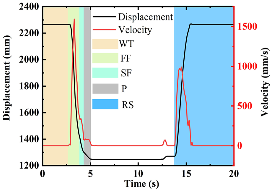
Large-scale high-speed equipment single production cycle motion diagram.
Trajectory curve optimization in motion control strategies for robotic arms and robots 23 effectively resolves minimum motion time and minimum motion impact coupling issues. Quintic polynomial curves 24 exhibit good acceleration continuity, effectively reducing the impact of motion on the movable crossbeam during high-speed motion. Considering the characteristics of fast descent motion in large-scale high-speed hydraulic forming equipment and under the constraints of a specified single-cycle displacement, time, acceleration, and jerk factors, a quintic polynomial curve was planned, as shown in equation (1).

where
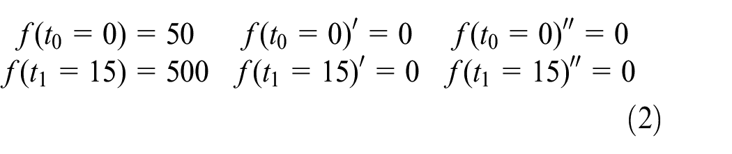
As shown in Figure 1, the motion at each stage of large-scale hydraulic press equipment is controlled by time-varying variables under feasible conditions, which also prevents the dead zone and impact effects in the hydraulic cylinder, ensuring that both the starting and ending displacements are less than the maximum stroke. Therefore, based on the maximum speed achievable by the test bench, the total motion time is set to 15 s. Secondly, to mitigate the influence of the hydraulic cylinder dead zone, the starting displacement is set at 50 mm and the ending displacement at 500 mm. According to the requirements for impact-free motion planning, the velocity and acceleration at both the start and end of the motion curve are set to zero to ensure smooth start and stop phases. Consequently, based on the quintic polynomial formula, the fundamental trajectory parameters can be derived as shown in equation (2), which further yields the polynomial matrix equation shown in equation (3).

Based on equation (3), the planned impact-free fast descent displacement and velocity curves are given by equation (4).

Cubic curves are widely used for motion trajectory planning and smooth trajectory optimization. Therefore, to effectively validate the application of quintic polynomial curves in large-scale high-speed hydraulic forming equipment, a cubic motion trajectory curve was designed using the parameters from the quintic polynomial curve, as shown in equation (5), and their initial parameters given by equation (6).


where
From equations (5) and (6), the cubic motion trajectory curve under the specified conditions of time, displacement, and velocity can be obtained as follows (equation (7)).

To enhance the comparative effect of the traditional motion curve control, three multi-segment polyline motion trajectory curves with initial speeds of 60, 40, and 10 mm/s were designed based on the cubic and quintic curves, as shown in equation (8).

Furthermore, five optimized motion curves for the impact-free motion strategy of a fast-descent hydraulic system with load-independent control based on high-response servo-valves are shown in Figure 2.

Quintic polynomial optimized motion curves: (a) displacement curve and (b) velocity curve.
Non-driven high-frequency servo valve controlled rapid descent hydraulic system
According to the design of the fast-descent hydraulic circuit system for large-scale high-speed hydraulic presses shown in Figure 3, the load-independent hydraulic system based on high-response proportional servo valves primarily consists of a servo motor, a fixed-displacement vane pump, a pressure-relief module, a high-response servo valve, an overflow valve, a pressure sensor, a hydraulic cylinder, and a heavy movable beam. In this system, the upper and lower chambers of the hydraulic cylinder were controlled by high-response proportional servo valves to regulate the flow rates during the oil supply and return processes. The power source mainly supports the return stroke movement of the movable beam during the experiment and does not participate in the fast descent motion. After the return stroke, the pressure-relief module completes the depressurization of the upper and lower chambers of the system, ensuring that a quick descent action can proceed without an external drive.

Schematic diagram of the hydraulic system.
During the quick descent process, the high-frequency-response servo valve controlling the upper chamber of the system was kept open. The hydraulic cylinder of the system had an internally mounted magnetic ring displacement sensor. The controller processed the displacement signals generated by the sensor and transmitted them to the high-frequency response servo valve in the lower chamber (U2) to achieve precise control of the low-impact motion of the movable crossbeam. The upper and lower chambers of the hydraulic cylinder were connected to pressure sensors to enable the real-time visualization and monitoring of pressure fluctuations through the control module. Additionally, the power-source module received a motor-speed signal only during the return process, allowing multiple tests to be conducted on the movement of the movable crossbeam.
Control system modeling
The principle of a fast-descent hydraulic system with load-independent control based on high-response proportional servo valves and no drive is illustrated in Figure 4. A mathematical model for the rapid descent stroke of servo-valve-controlled hydraulic cylinders was established based on the motion characteristics of a large-mass moving beam. 25

Principle of non-driven high-frequency servo-valve rapid descent hydraulic systems.
According to the requirements of the movement scheme, the downward motion of the movable beam is defined as the positive direction. The motion of the movable beam is solely provided by the large mass of the movable beam. Hence, the dynamic force balance equation of the valve-controlled cylinder can be derived as shown in equation (9).

where
The dynamic motion flow equation of the hydraulic cylinder is given by equation (10).
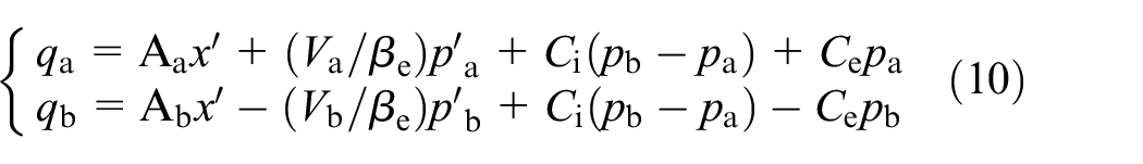
where
According to the flow equation of the spool valve in the valve-controlled cylinder system, the linearized flow equation of the system can be derived as shown in equation (11).

where
As shown in Figure 2, large-scale high-speed hydraulic systems exhibit significant nonlinear behavior. A sliding mode controller,
26
known for its strong robustness, was selected to address these challenges in hydraulic systems. Based on a hydraulic system control strategy,
27
the closed-loop transfer parameter is defined as the displacement (
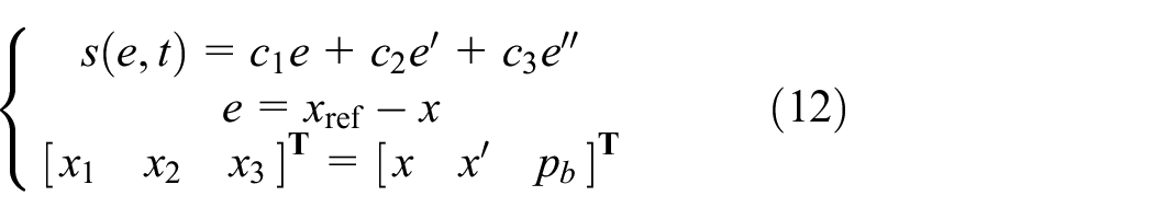
where
Equations (9)–(12) yield equation (13).

where
Given that the controller sliding surface function follows the classical sliding mode control approach


Equation (16) can be derived from equations (13) to (15), which in turn allows for the determination of the system control voltage (


where

To verify the stability of the sliding mode controller constructed from the above equations, we first define the Lyapunov function (
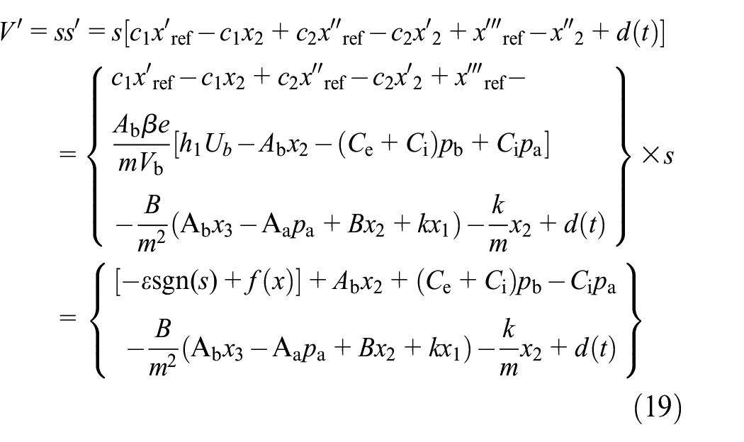
In equation (19), to ensure the stability of the sliding mode controller,
Experimental validation
Building experimental platform
A large-mass movable-beam test platform was established to investigate the effectiveness of a load-independent fast-descent hydraulic system with high-response proportional servo valves for large-scale high-speed hydraulic presses based on curve optimization. The main components and parameters of the system are listed in Table 1.
Main hydraulic components and their parameters.

As illustrated in Figure 5, the test rig includes a high-voltage power supply cabinet, control platform, hydraulic press central unit, valve block platform, and hydraulic station. The large-mass movable beam is directly connected to the hydraulic cylinder via a flange with high-response proportional servo valves mounted on the valve block. The hydraulic pipelines of the primary circuit are connected using high-pressure hoses. The system collects analog data for the movable beam displacement and pressures at both ends of the hydraulic cylinder using PCI-1751 and PCI-1713 acquisition cards, respectively. The Simulink real-time platform performs data recognition, visualization, and closed-loop control. Control of the high-response servo valve openings is achieved using the output module and the PCI-6703 output card. In addition, to facilitate more realistic and convenient motion testing, the PCI-1751 acquisition card supports digital data acquisition and output functions. This enables multiplatform coordinated control involving the hydraulic press, Simulink platform, and control console, thus establishing a more streamlined experimental setup.

Experimental platform for the motion of heavy-duty movable beams.
Experimental data analysis
Figure 6 illustrates the tracking performance of five different motion trajectory curves. Figure 6(a) and (b) show the best tracking results, where the quintic polynomial and cubic curves closely follow the ideal input curves with no significant deviations or jumps, significantly outperforming the results in Figure 6(c) and (e). Figure 6(c) and (e) show significant speed transition points, resulting in substantial displacement tracking errors after the transitions, whether from low to high speed or vice versa. Conversely, Figure 6(d) shows minor speed variations before and after the two transition points, with a generally stable tracking performance. Therefore, the continuously smooth curves after planning demonstrate better performance, achieving continuous and stable displacement variations and effectively addressing displacement jumps at the transition points observed with the traditional linear curves. To better quantify the displacement tracking accuracy, the data extracted from Figure 6 were further analyzed to produce the displacement tracking error curve shown in Figure 7, and the critical parameters of the displacement tracking error are depicted in Figure 8.
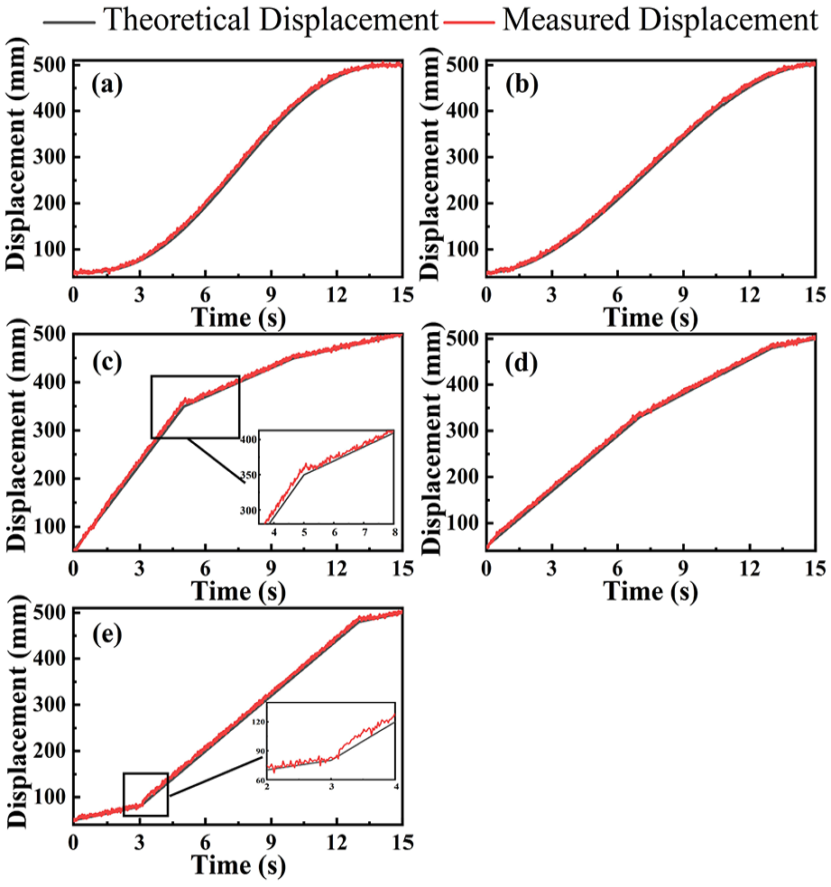
Displacement tracking motion curves: (a) quintic polynomial tracking displacement, (b) cubic polynomial tracking displacement, (c) high-speed polyline tracking displacement, (d) medium-speed polyline tracking displacement, and (e) low-speed polyline tracking displacement.

Displacement tracking error curve.

Analysis diagram of critical parameters for displacement tracking error: (A) quintic curve approach; (B) cubic curve approach; (C) high-speed polyline method; (D) medium-speed polyline method; and (E) low-speed polyline method.
As shown in Figure 7, the displacement tracking error increased with more extensive speed changes at the transition points of the piecewise motion trajectories. However, the error curves after the transitions were relatively stable with no significant jitter, and the tracking errors decreased at slower speeds within the same timeframe. The cubic and quintic polynomial curves exhibited no significant displacement error oscillations at the start and end stages; however, some displacement error fluctuations occurred in the intermediate phases. These fluctuations were due to the smooth transitions of the cubic and quintic polynomial curves, which continuously alter the speed, causing the sliding mode controller to adjust the error feedback. Despite this, the overall displacement tracking accuracy of these curves remained superior to the piecewise curves. In addition, the cubic curve had a more pronounced error jitter at the start and end stages than the quintic polynomial curve. Therefore, among the quintic polynomial curve models, the quintic polynomial curve exhibited the smallest amplitude of fluctuation and the most stable motion error within a specified time.
To further describe the displacement tracking accuracy, the average and extreme values of the displacement tracking error from Figure 7 were compared. The critical parameters of the displacement tracking error are shown in Figure 8. Under the same experimental conditions, the quintic polynomial curve and low-speed piecewise motion curve had relatively small average tracking errors, with the quintic polynomial curve reducing the errors by approximately 42% compared to the cubic curve. The minimum tracking error for the quintic polynomial curve was 65.6% lower than that of the cubic curve and 38.9% lower than that of the minimum error observed in the low-speed piecewise trajectory. Although the cubic curve exhibited a smaller maximum displacement error than the quintic polynomial curve (14.3% lower), its average and minimum error performances were significantly inferior to those of the quintic polynomial trajectory curve.
As illustrated in Figures 9 and 10, to further investigate the stability of the proposed scheme, eight repeated experiments were conducted for both the proposed scheme and the comparison models, and the mean error, standard deviation, and 95% confidence interval data were extracted. The significance analysis of the repeated experiments was also carried out. These repeated tests were carried out successively at the same time, in the same place and on the same equipment. Figures 8 and 9 reveal that the high-speed polyline tracking displacement data demonstrate low repeatability and instability in the linear closed-loop motion control of large hydraulic press equipment during high-speed operation. Notably, the proposed scheme achieved an average error of only 2.83 mm, representing a 13.98% improvement over the best-performing comparison model. Furthermore, the standard deviation of the proposed model is only 1.41, and its 95% confidence interval is more compact, thereby fully demonstrating the application stability of the proposed scheme. As shown in Figure 10, through the tracking motion repetition experimental error data of the five-degree curve, the significance p-value analysis was conducted respectively with the control group. Among them, the p values of the high-speed, medium-speed, and low-speed broken lines are between 0.05 and 0.1, showing a significant trend difference, especially for the high-speed broken line motion curve, there is a highly significant difference. Although the difference between the control groups of the cubic curve was not significant, it can be obtained more intuitively through the data verification in Figures 8 and 9 that the cubic curve has a smaller retention of motion error.

Parameter graph of standard deviation and mean confidence interval: (A) quintic curve approach; (B) cubic curve approach; (C) high-speed polyline method; (D) medium-speed polyline method; and (E) low-speed polyline method.

Significance analysis of repeated trials: (A) quintic curve approach; (B) cubic curve approach; (C) high-speed polyline method; (D) medium-speed polyline method; and (E) low-speed polyline method.
In summary, the displacement-related data for the five motion trajectory curves demonstrated that the quintic polynomial curve exhibited high precision in displacement tracking and a lower motion error. In addition, the quintic polynomial curve exhibited the highest precision in the displacement error at the termination stage, effectively improving the production quality of the equipment.
As shown in Figure 11, the quintic polynomial and cubic motion trajectory curves were continuously optimized within a specified time, with the lower chamber pressure remaining stable and continuously varying without significant abrupt changes. Figure 12(a) and (b) indicate that during the start-up phase of the movable beam motion, lower starting speeds resulted in more noticeable oscillations in the lower chamber pressure. However, the amplitude was relatively small and did not directly affect the motion speed fluctuations. Furthermore, the lower-chamber pressure curves for the three piecewise trajectory modes show that each speed transition point is associated with a gradual pressure spike. This gradual change in pressure can substantially affect the system, leading to vibrations and noise.

Pressure in the lower chamber of the hydraulic cylinder: (a) quintic polynomial trajectory pressure, (b) cubic polynomial trajectory pressure, (c) high-speed polyline trajectory pressure, (d) medium-speed polyline trajectory pressure, and (e) low-speed polyline trajectory pressure.

Speed and maximum speed amplitude of the movable beam: (a) the movement speed of the movable crossbeam and (b) Maximum velocity amplitude of the movable crossbeam; (A) quintic polynomial trajectory displacement; (B) cubic polynomial trajectory displacement; (C) high-speed polyline trajectory displacement; (D) medium-speed polyline trajectory displacement; and (E) low-speed polyline trajectory displacement.
Figure 12(a) clearly illustrates the magnitude and trend of the speed changes during the motion of the movable beam. Significant speed jitters occurred at the pressure spike locations corresponding to Figure 9. All three piecewise trajectory curves caused substantial speed transitions at the transition points, which generated considerable inertial impacts during the movement of the large-mass movable beam. Although the cubic trajectory curve exhibited continuous changes during motion, its nonzero starting and ending speeds led to larger, harder-to-optimize speed amplitudes in the 0–3 s phase compared to the quintic polynomial curve, causing persistent speed impacts on the system. Figure 12(b) presents the maximum amplitude curves for the five motion trajectory curves, where the quintic polynomial curve shows a significantly lower speed, approximately 64.2% less than the cubic trajectory curve and approximately 76.2% less than the average speed amplitude of the three piecewise trajectory curves.
These findings further validate that the optimized quintic polynomial curve, in conjunction with the high-response proportional servo-valve load-independent hydraulic system and sliding mode controller, exhibits high precision and stability. This demonstrates the system’s capability to significantly reduce the impact experienced by traditional motion curve tracking control.
Conclusions and future work
To address the issues of impact, noise, and motion accuracy in the production of large-scale high-speed hydraulic forming equipment, this study proposes a high-performance motion solution based on the optimization of the quintic polynomial curve, incorporating a load-independent hydraulic system with a high-frequency response proportional servo valve, and utilizing a sliding mode controller. A quintic polynomial curve planning scheme was established under specific motion parameter requirements. The hydraulic principles were improved according to the motion process of the large mass-forming equipment, and the performance of the existing system was significantly enhanced by integrating a sliding mode controller. The experimental results demonstrated that compared to the cubic trajectory motion curve scheme with the same optimization, the proposed solution improved the motion accuracy by 65.6% and reduced the speed fluctuations by 64.2%. Compared with traditional motion schemes, it achieved a 38.9% increase in motion accuracy and a 76.2% reduction in speed fluctuations. In summary, the design scheme was validated through multiple experimental comparisons, confirming its ability to satisfy the demands for motion accuracy and speed stability in large-scale high-speed forming equipment with superior performance.
This study investigated the impact of the rapid descent of large-scale, high-speed hydraulic forming equipment on precision and stability. However, the change of different production environment is relatively complicated, and the coordination of multi-cylinder movement increases the difficulty of motion curve planning. At the same time, the sliding mode controller is relatively sensitive to the influence of noise, and the complex production environment of large hydraulic press equipment will have an irreversible impact on the application stability of the sliding mode controller. Therefore, future research will focus on the joint planning of multicylinder motion curves and the exploration of stable hydraulic principles and advanced controllers. This research lays the foundation for enhancing the reliability of production operations, improving the component forming quality, and promoting the industrial application of large-scale, high-speed hydraulic forming equipment.
Footnotes
Acknowledgements
The authors thank the Technology Innovation Center of Anhui Province and Hefei Metal Forming Intelligent Manufacturing Co., Ltd., for providing financial support for the publication of this research.
Handling Editor: Sharmili Pandian
Author contributions
Qiong Liu: Writing – original draft, Writing – review & editing, Conceptualization, Methodology, Validation, Data curation. Chen Yang: Software, Validation, Resources. Jianwen Yan: Conceptualization, Methodology, Writing – review and editing, Supervision, Funding acquisition. Quan Zuo: Formal analysis, Software, Data curation. Yucheng Cheng: Resources, Software.
Funding
The author(s) disclosed receipt of the following financial support for the research, authorship, and/or publication of this article: This research was funded by the 2020 Anhui Province Science and Technology Major Special Project: Intelligent Hydraulic Forming Process and Equipment for Lightweight Components and Industrialization (Grant No.: 202003a05020034); Hefei Postdoctoral Scientific Research Project: Research and Development of Key Technologies for High-Speed Composite Molding Hydraulic Equipment; and Demonstration project of hot stamping forming production based on domestic press and roll-bottom heating furnaces (Grant No.: 2018ZX04023002-004).
Declaration of conflicting interests
The author(s) declared no potential conflicts of interest with respect to the research, authorship, and/or publication of this article.
Data availability statement
The data associated with the study are not deposited into a publicly available repository. Data will be made available on request.