
Abstract
Anti-disturbance vibration control is a crucial component in a hydraulic suspension system. However, random input excitation and prolonged service can cause hydraulic suspension system parameters to drift, leading to system vibration with suppression failure. The resulting states of nonlinearity and disturbance will lead to a gradual deterioration of pressure control. Therefore, designing a viable controller for a hydraulic suspension system that considers system nonlinearity, computing capacity, and sensor configuration is essential. To address this need, we present a double-layer control strategy in this work. A hybrid sliding mode control algorithm based on the reference skyhook and groundhook model is proposed to regulate the expected force of reverse compensation. An output controller is then applied based on the expected force observer to mitigate low-frequency vibrations to realize a steady state. A logic rule is designed to ensure that the two controllers work to suppress sprung mass vibration, and a comprehensive system model is derived to help characterize system nonlinearities and design the hybrid sliding model controller. Numerical and physical validations are then carried out to demonstrate the feasibility of the strategy and test the performance of the controller. The experimental results show that the hybrid sliding mode controller can suppress vibration under disturbance excitation and reduce the vibration acceleration to a 2.3 m/s2 random response when system parameters vary.
Keywords
1. Introduction
The hydraulic suspension system is vital to ensure riding comfort in off-road vehicles by exerting lifting force and implementing active damping control. This is particularly important, when a vehicle operates under random disturbance conditions in which road excitation fluctuation can lead to dynamic instability (Gao et al., 2020; Taghavifar, 2020; Yoon et al., 2021). The dynamic model and tracking regulator are important components for obtaining appropriate control performance (Gong et al., 2019; Taghavifar et al., 2019; Wang et al., 2021). At present, it is expected that the hydraulic suspension system will be a standard requirement in driverless off-road vehicles (Herrmann et al., 2018; Termous et al., 2019). Research exploring how to reduce disturbance and obtain stable control of hydraulic suspension systems in random conditions is significant to improve off-road vehicle safety.
Hydraulic oil is the power transmitting medium in hydraulic suspension system, and its viscosity, temperature, and input excitation will influence the system’s operation (Ma, Wong and Zhao, 2019; Meng et al., 2020). In addition, different hydraulic circuits generate different flow behavior of the pressed hydraulic oil. These nonlinearities present a challenge when designing hydraulic suspension system control with desired performance. Many scholars have explored hydraulic suspension system nonlinearity and modeling, such as linear quadratic regulation (Vu et al., 2017), H-infinity control, and adaptive control (Al Aela et al., 2022; Jibril, 2020; Na et al., 2017). The sliding mode controller can also be applied to complicated systems with uncertain parameters, such as fuzzy sliding mode control and fuzzy neural network control (Huang et al., 2021; Liang et al., 2020; Ma, Wong, Zhao, et al., 2019; Senthil Kumar et al., 2018; Sun and Zhao, 2020). Many methods have been proposed to obtain expected control performance subject to specific conditions (Bououden et al., 2016; Khodadadi and Ghadiri, 2018; Pang et al., 2019; Savaresi et al., 2010; Zeng et al., 2022). However, random input and disturbance remain challenging when attempting to improve control performance (Hasbullah et al., 2015; Kim et al., 2002). For instance, vertical load or displacement variations can sway system parameters over a certain deployment time and negatively impact the characteristics of the hydraulic suspension system in an unpredictable manner. Robust control and adaptive control theory with self-tuning ability have been applied in the controller design process of active suspension systems (Huang et al., 2018; Wu Qin et al., 2021a). However, with the development of self-driving off-road vehicles, to decrease energy consumption, the active hydraulic suspension system switches frequently at a certain frequency to obtain maximum energy efficiency. This switching process results in a decline in tracking performance, exacerbating the drift in system parameters. Therefore, it is necessary to account for system parameter variations experienced by the hydraulic actuator when designing the controller.
Proportional valves serve as the pivotal hydraulic regulators in a hydraulic suspension system (Meng et al., 2015). They convert electronic signals from the control unit to the hydraulic actuator to generate output force in a suspension system and regulate the output force according to the control signal when active control is used. The hydraulic control unit must be carefully designed to provide redundancy and maintain smooth conversion when subject to the influences of the nonlinear factors mentioned above. Therefore, it is important to consider many state variables for the hydraulic circuit design.
Given its inherent characteristics, the design of a hydraulic circuit is primarily based on steady-state models, where the initial system parameters can ensure control system stability. However, system parameters can drift due to input disturbance and the influence of working conditions on the control strategy. Thus, hydraulic suspension systems are designed with a series of states to display complex nonlinear response modes that are the coupled states of system parameter variables. Random excitation and step response are typical responses (Lian, 2012; Ren et al., 2016). A hydraulic suspension system in either of these states will vibrate, causing deteriorating control performance. As the input excitation does not indicate its regular pattern such as intervention time and intensity, but rather an unpredictable condition variable, it is extremely difficult to predict.
To address this issue, we present a hybrid sliding mode controller to minimize the vibration caused by input signal variation to maintain hydraulic suspension system stability. The engineering requirements of the displacement and pressure sensors and microchip capacity are considered in the design. A sliding mode variable structure algorithm is proposed based on the skyhook and groundhook model to generate the desired output force. An expected output regulator is then applied to mitigate the low-frequency vibrations to realize the steady state of the hydraulic suspension system. The remaining paper is organized as follows. Section 2 analyzes the hydraulic suspension system model, the working mechanism of the proportional valve, and the nonlinear behaviors of the system, which are presented on the basis of a mathematical model. Section 3 discusses the vibration suppression strategy and controller design. In Section 4, numerical analysis and testing are employed to validate the proposed design. Finally, conclusions are given in Section 5.
2. Hydraulic suspension system model
2.1. System construction
Figure 1 shows a general hydraulic suspension system. The system consists of an oil supply subsystem, a control unit, an accumulator, a hydraulic control subsystem, and a hydraulic cylinder. The hydraulic control subsystem includes a three-position four-way proportional valve, three throttle valves, and a pressure sensor used for measuring the pressure in the load chamber of the hydraulic circuit. The control unit is adopted to collect signals from the displacement sensor and pressure sensor, and the control signal is outputted based on the designed controller. The accumulator is then used to stabilize the pressure oscillation in the hydraulic circuit. Schematic of the hydraulic suspension system.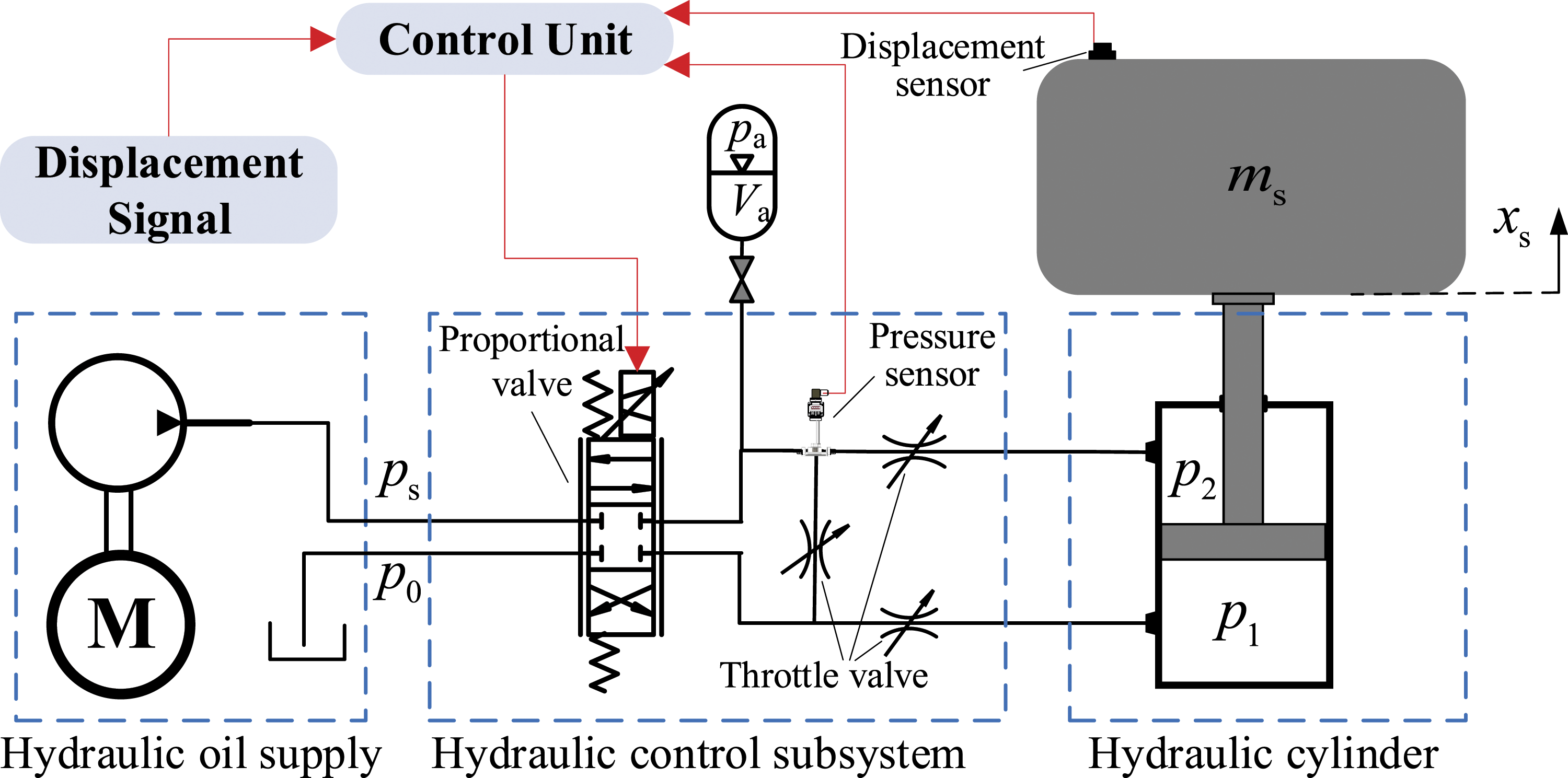
Figure 2 defines spool valve displacement with the corresponding mode of action. At the initial position, action ports 1 and 2 are disconnected from the hydraulic cylinder, and the suspension system is locked. When the spool valve is moved to the left, valve port 1 connects with the rodless chamber, allowing the hydraulic oil supplier to transport high-pressure hydraulic oil through the rodless chamber, which then extends the piston rod of the hydraulic cylinder. While the piston rod reaches the target place, the spool valve closes the action port with the hydraulic cylinder, and the load–displacement of the hydraulic cylinder remains stabilized. When the spool valve is moved to the right, valve port 2 connects with the rod chamber, reducing the chamber’s pressure, which then retracts the piston rod of the hydraulic cylinder. With input excitation disturbance, the hydraulic cylinder output force of the load causes the reverse compensation of the load’s movement, and the vibration tends to reduce. As this relationship is correlated with the hydraulic cylinder output force, the proportional valve can control the vibration suppression. At the termination of actuation, the piston rod moves down rapidly under the action of the proportional valve, allowing high-pressure oil in the hydraulic cylinder to be discharged. Orifice model of three-position four-way proportional valve.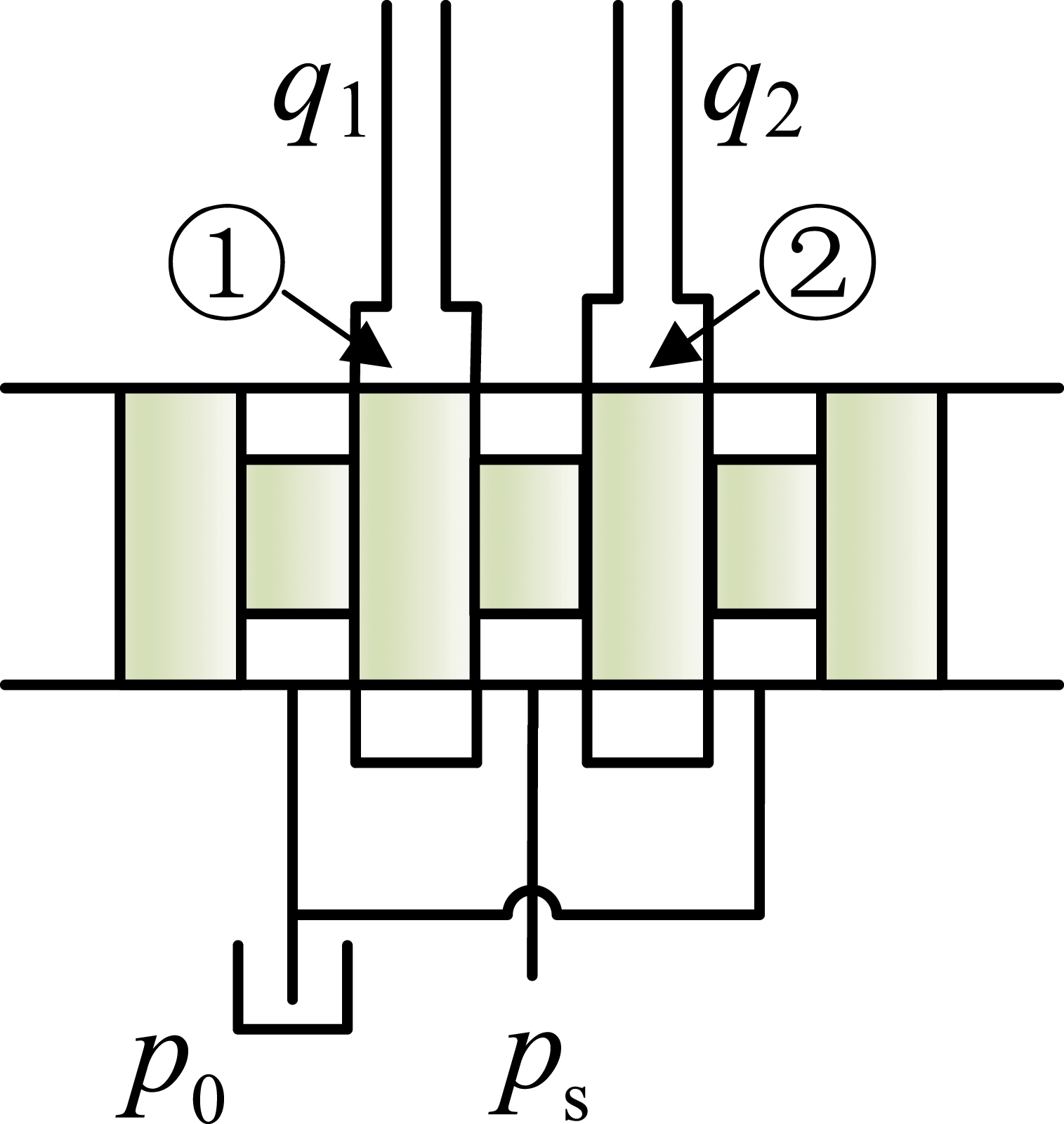
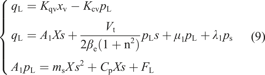
2.2. Mathematical model
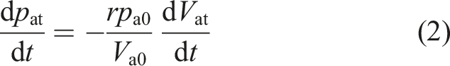
The mechanism described in Figure 1 and the defined system variables are employed to establish a corresponding mathematical model. As the medium for transmitting power, the hydraulic oil in the hydraulic circuit must generate sufficient pressure to actuate the hydraulic control subsystem. The pressure state of the hydraulic oil changes with the extension and retraction of the hydraulic cylinder in this process. In general, the leakage of gas and hydraulic oil in the hydraulic circuit system is ignored. Additionally, because gas changing in the accumulator is relatively fast and intense, the variation of the gas in the accumulator can be regarded as adiabatic, and the time delay of pressure transmission between the gas and hydraulic oil in the accumulator can be assumed as negligible. We use gas state equation to express the relationship at the two states

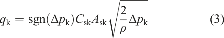
The throttle valve can be regarded as a short hole and can be adjusted to control the hydraulic oil flow between the accumulator and the hydraulic cylinder. The flow formula for the throttle valve is
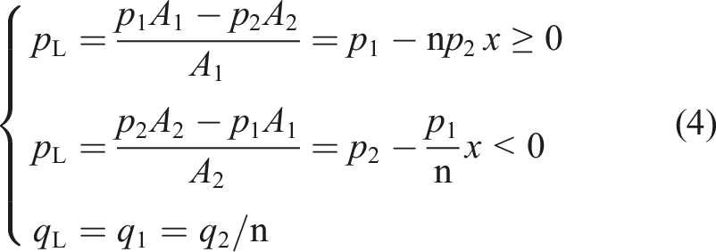
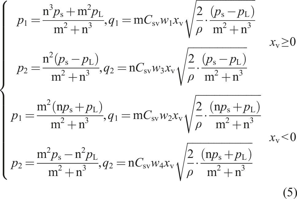
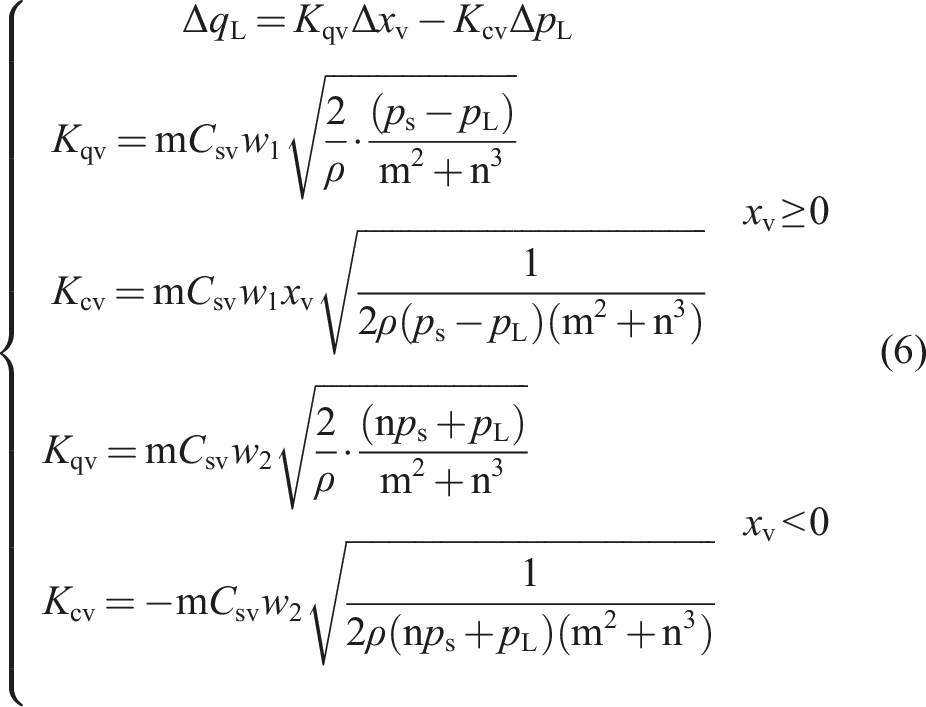
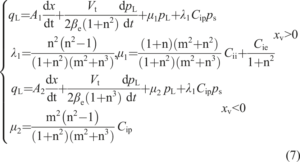
Combining equations (5) and (4) provides

2.3. System response characteristics
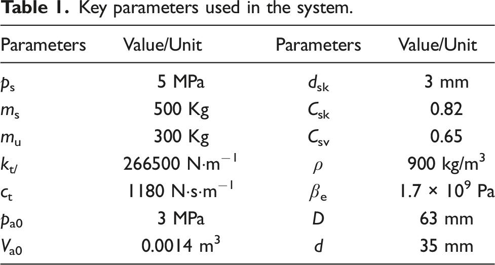
Key parameters used in the system.
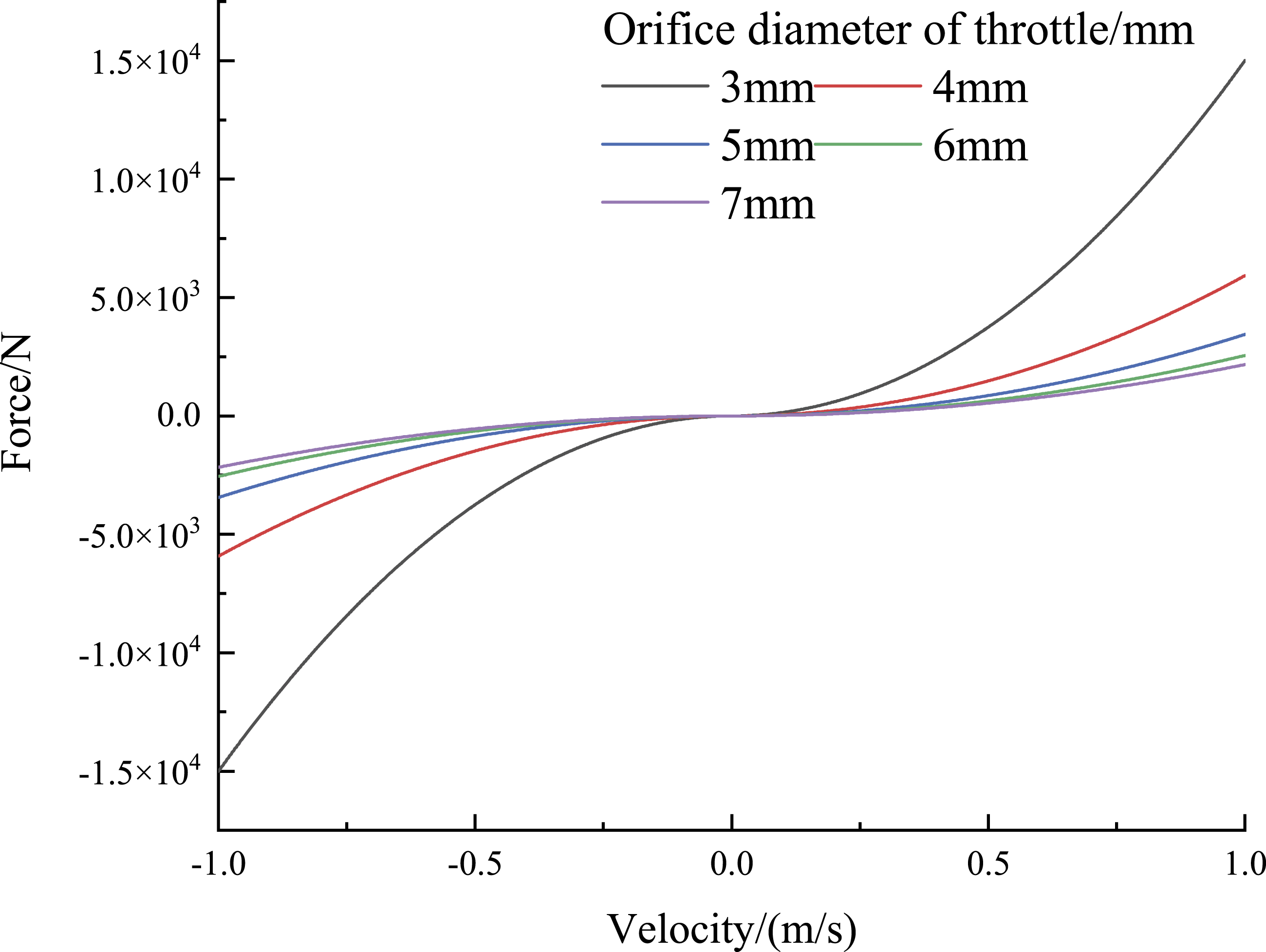
Nonlinear response with varying dsk.
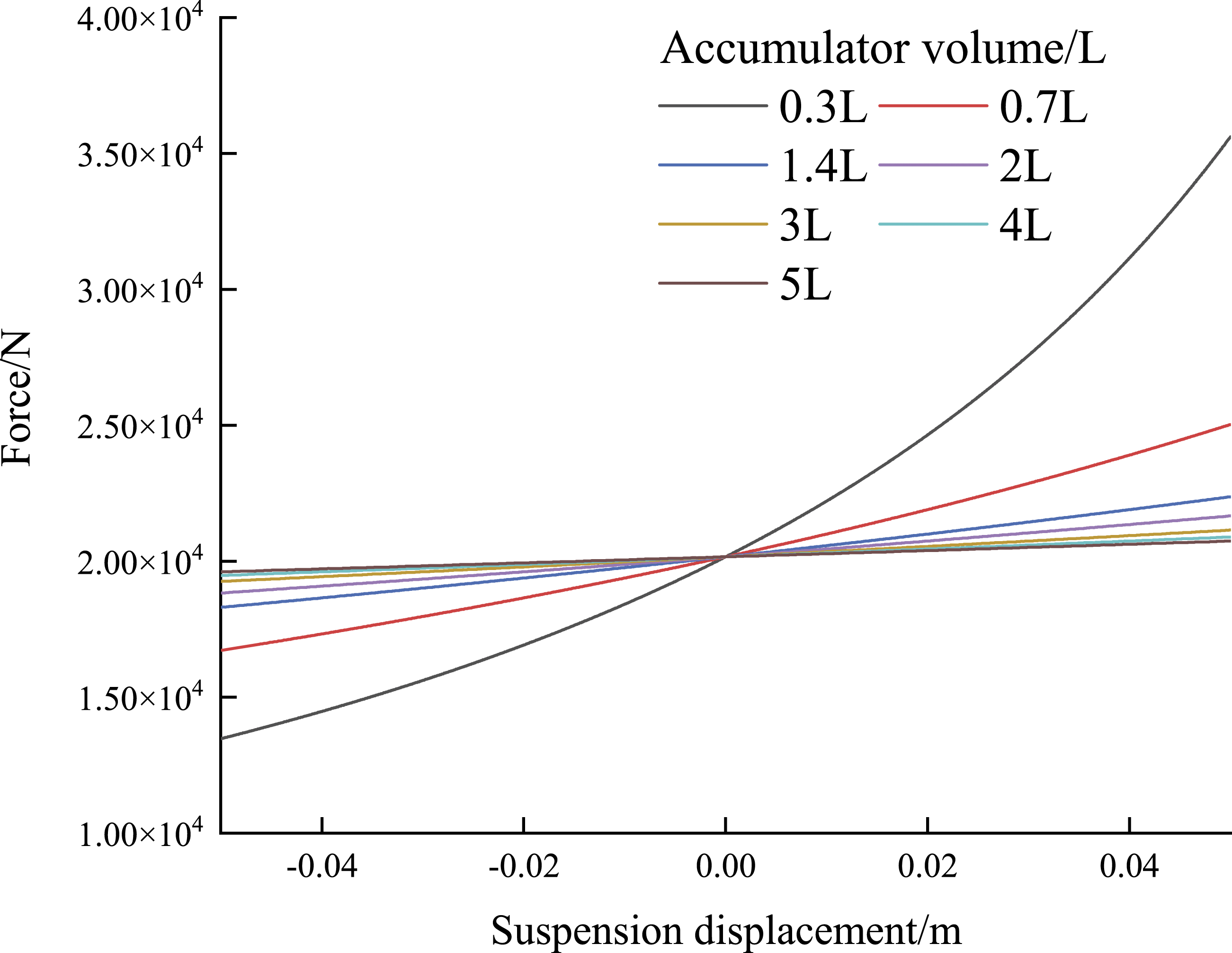
Nonlinear response with varying Vat.
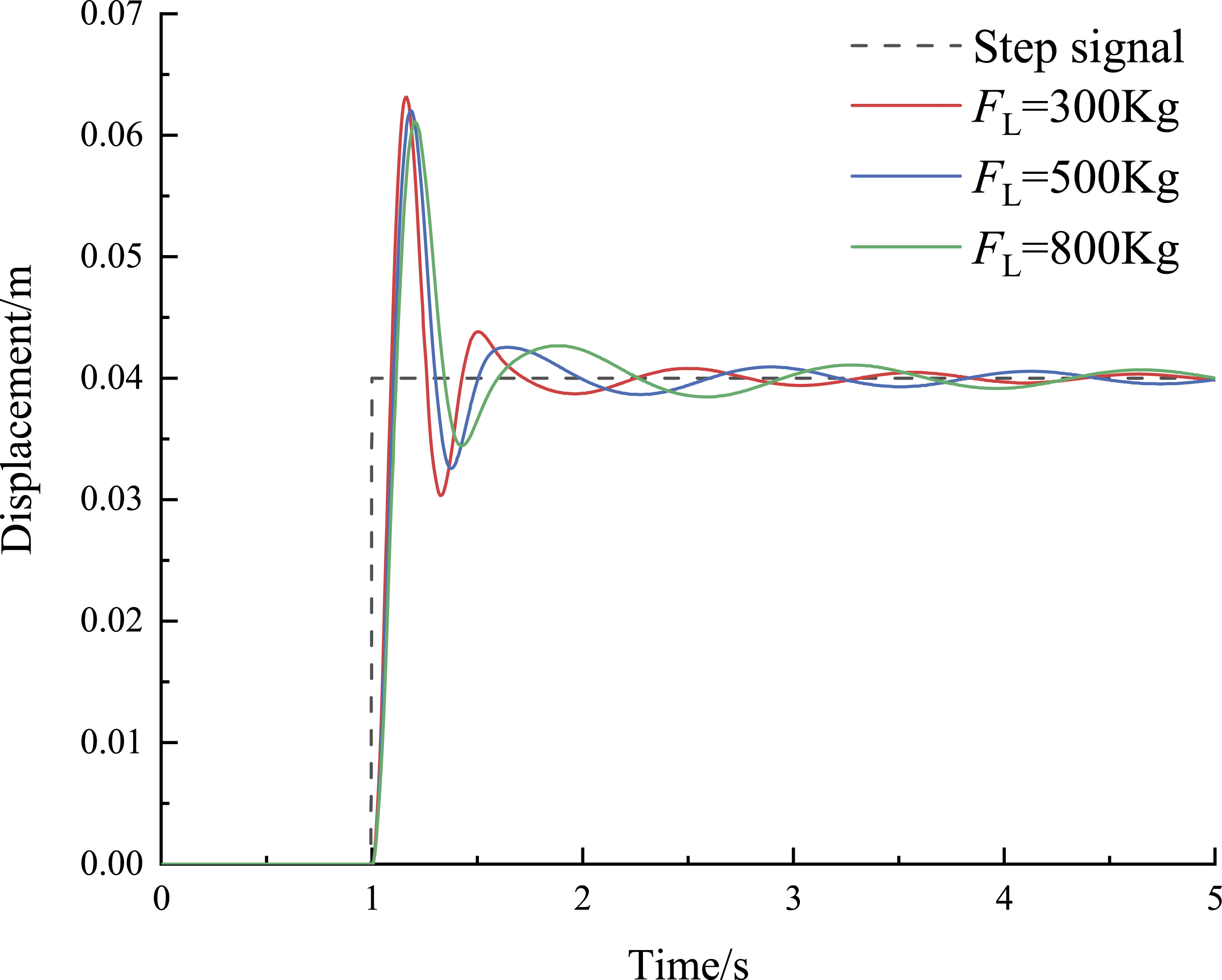
Nonlinear response with varying FL.
The hydraulic cylinder output force will eventually stabilize at the target output force under the open-loop condition. However, oscillations occur in the state of disturbance input excitation owing to the nonlinear mechanism and the closed-loop proportional control in Figures 3, 4, and 5. The oscillations can be explained by the displacement of the three-position four-way proportional valve piston. Parameter variation leads to rapid changes in the valve piston and inadvertently induces load mass vibration, which is a mode of nonlinear response. This requires the deployment of a vibration suppression controller.
3. Hybrid sliding mode controller design
It is difficult to suppress full-frequency vibration in a nonlinear system using direct feedback control. An effective solution to this problem is to separate the control frequency and correspond this to different control methods (W. Qin et al., 2021b; Roy and Kar, 2020; Zhang et al., 2018). The double-layer control strategy is depicted in Figure 6. One layer works to calculate the desired output force, using a set of weighted skyhooks and groundhooks as the reference input. The other is a state tracking controller based on an expected force observer. Conditions are used to define the logic rule needed to bridge the two layers. The first condition depends on the frequency component and is used to trigger the time–frequency analysis. The second condition enables the expected output force regulation and the third condition is used to add the desired output feedback into the control action, both relying on the judgment of the expected output value of the weighted skyhook and groundhook. The factors informing these logical rules are illustrated in the following section. Schematic of the hybrid sliding mode controller.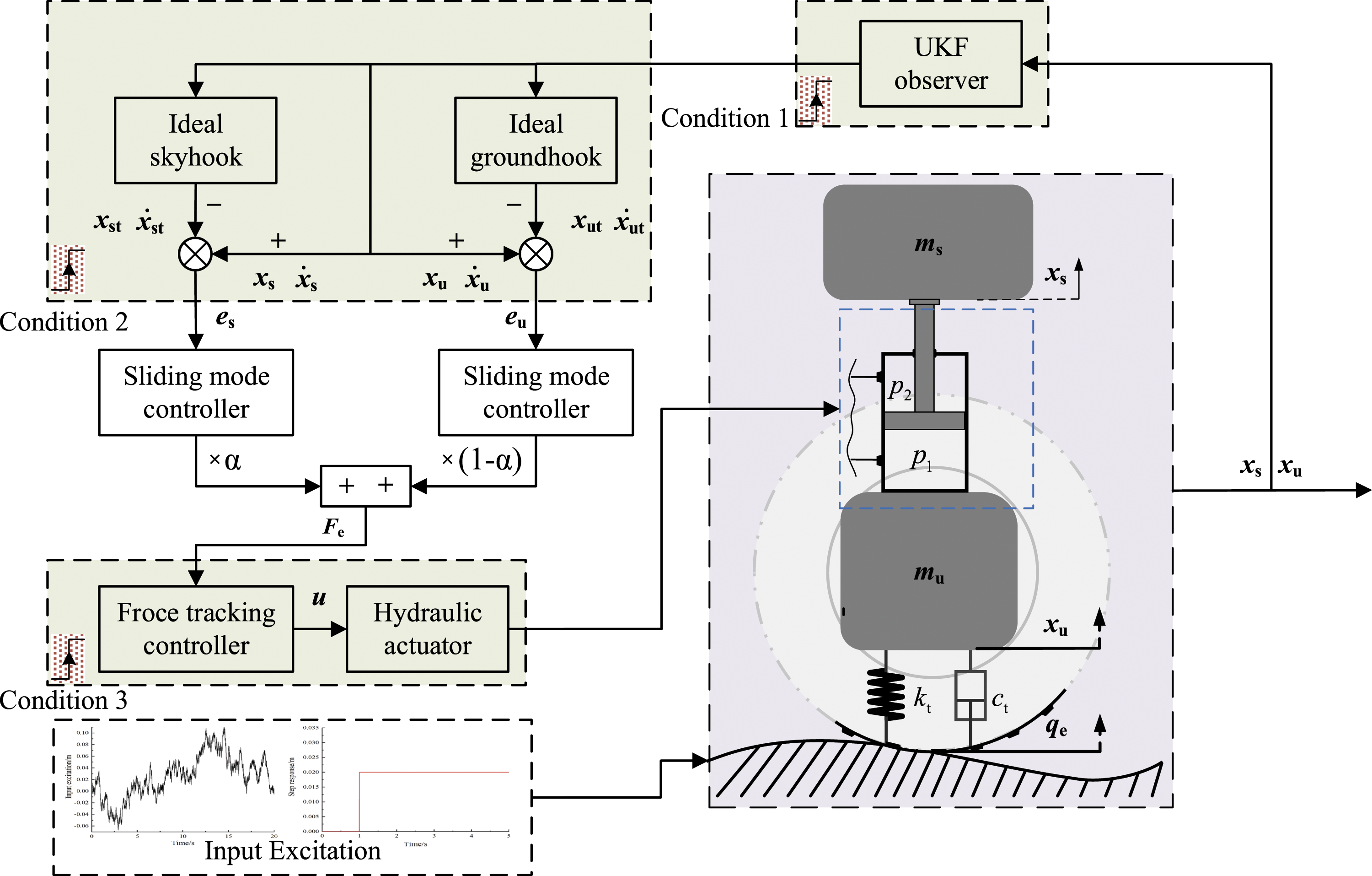
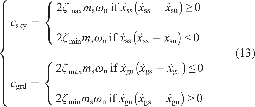
3.1. Calculation of skyhook and groundhook output force
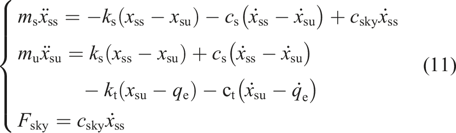
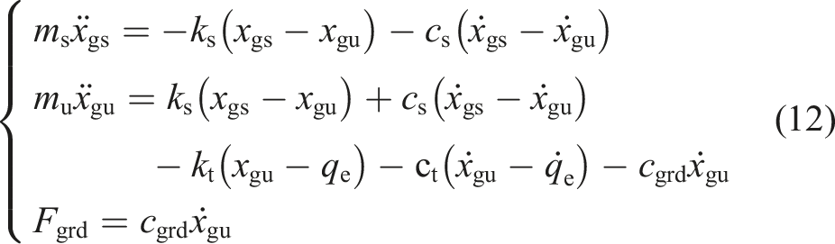
When the hydraulic suspension system demonstrates nonlinearities, high-frequency vibration does not provide enough time for an active damping controller to operate due to the practical limitations of the hydraulic system response capabilities. High-frequency oscillations can be reduced via dissipated energy through the rapid reciprocating motion of the accumulator diaphragm. It is more practical to minimize the negative impact of low-frequency vibration on the hydraulic suspension system using different control methods. In general, an ideal skyhook and groundhook method will provide a satisfactory vibration-suppressing performance, where the ideal skyhook improves ride comfort and the groundhook reduces the dynamic load of the tires. Therefore, a weighted ideal skyhook and groundhook method is adopted in this work.
Introducing the hybrid adjustment coefficient α to regulate the mixing degree of the skyhook and groundhook algorithm, the hybrid sliding mode variable structure real-time control force Fe can be expressed as
3.2. Hybrid sliding mode controller
A feedforward system for the expected output force regulator is used in hydraulic suspension output force generator systems to enhance the reverse suppression performance or harmonic cancellation. As a kind of the reverse compensation control method, it often cooperates with a feedback controller to further improve control accuracy. The benefits of a feedforward system are that model estimation can be modified according to the situation with weighted and that the algorithm used for calculation after filtering input runs rapidly in a microcontroller. Figure 6 provides the schematic of the hybrid sliding mode controller.
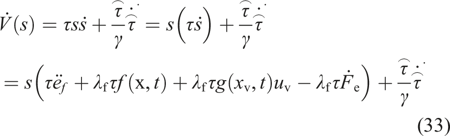
The sliding mode control design of ideal skyhook is taken as an example. If the tracking error is defined as es, es = [es1 es2 es3]T = [∫(xst-xss) xst-xss xst-xss]T, then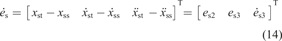

The sliding surface is set to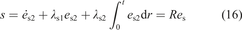
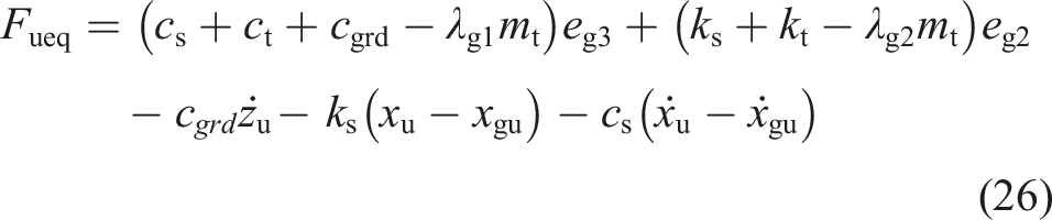
Assuming that the error is in the sliding mode plane, then s = ṡ = 0, ės3 is substituted into ṡ = 0, and the equivalent skyhook control output force in the sliding mode is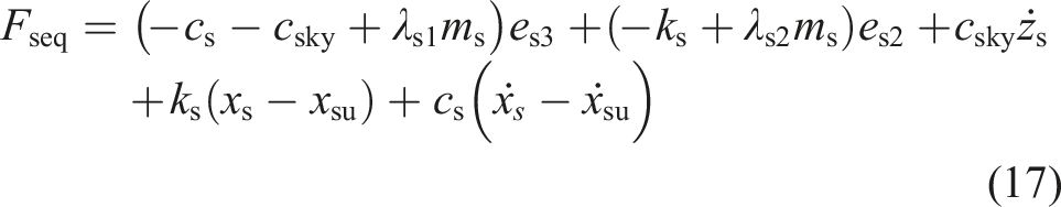
The discontinuous disturbance term ε·sgn(s) is added to enhance system robustness, where ε is the approach ratio, ε > 0, and then
If the Lyapunov function is employed


The continuous saturation function sat(s/ϕ) is used to replace sgn(s), ϕ = 0.1, and then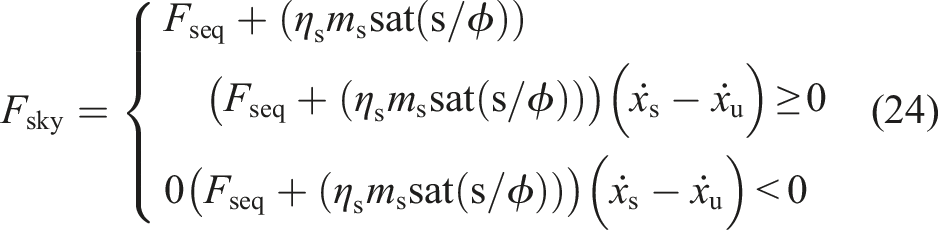
The ideal groundhook sliding mode variable structure control force can be obtained using the same principle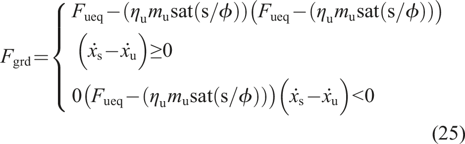
3.3. Expect output regulator and control strategy
The expected output regulator method is used to adjust the hydraulic suspension output force when Fe is calculated. The use of the design regulator is common when developing precise and robust hydraulic system controllers that are employed in many situations. An expected output regulator is a useful method employed in the feedback control design for vibration suppression, which can be applied in many systems, including a single-input single-output system. Figure 7 gives the schematic of the force tracking controller based on a sliding mode variable structure. Schematic of the force tracking controller.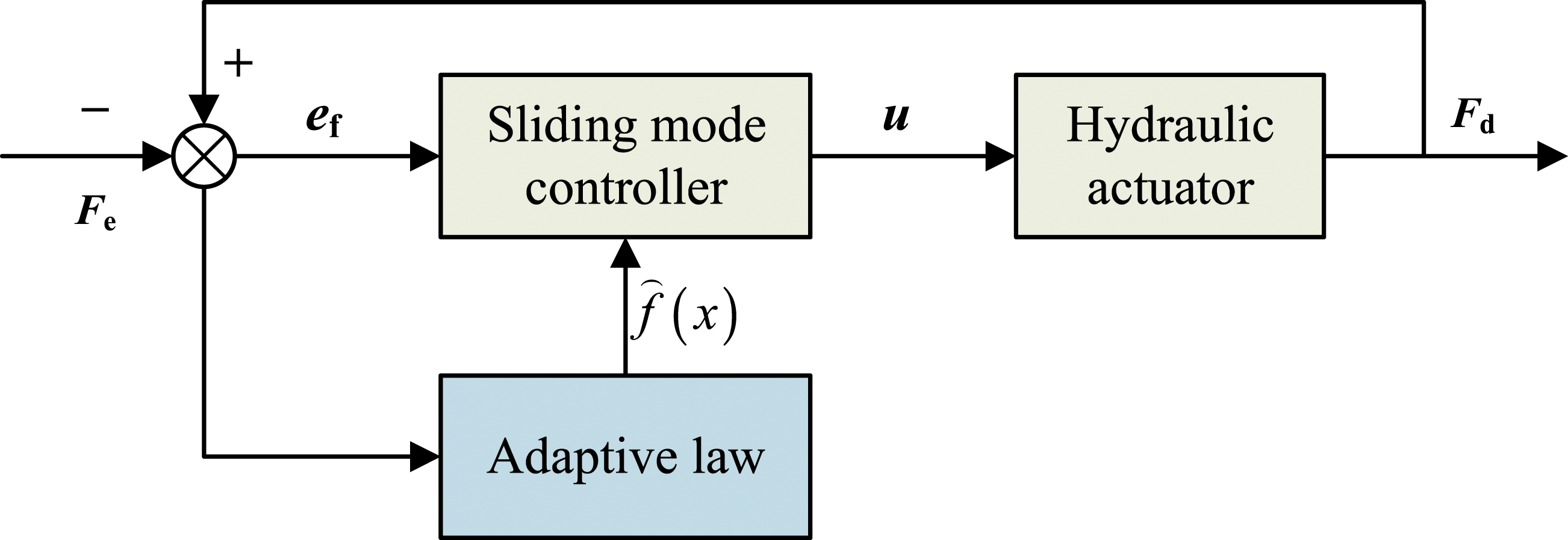
Using the model from Section 2, the system model can be acquired by combining equations (7) and (5)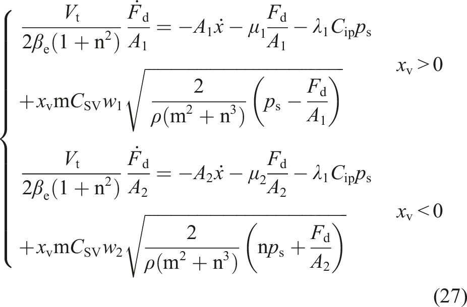
Additionally, assuming kv is the coefficient between the spool displacement xv and the voltage uv of the proportional valve, then
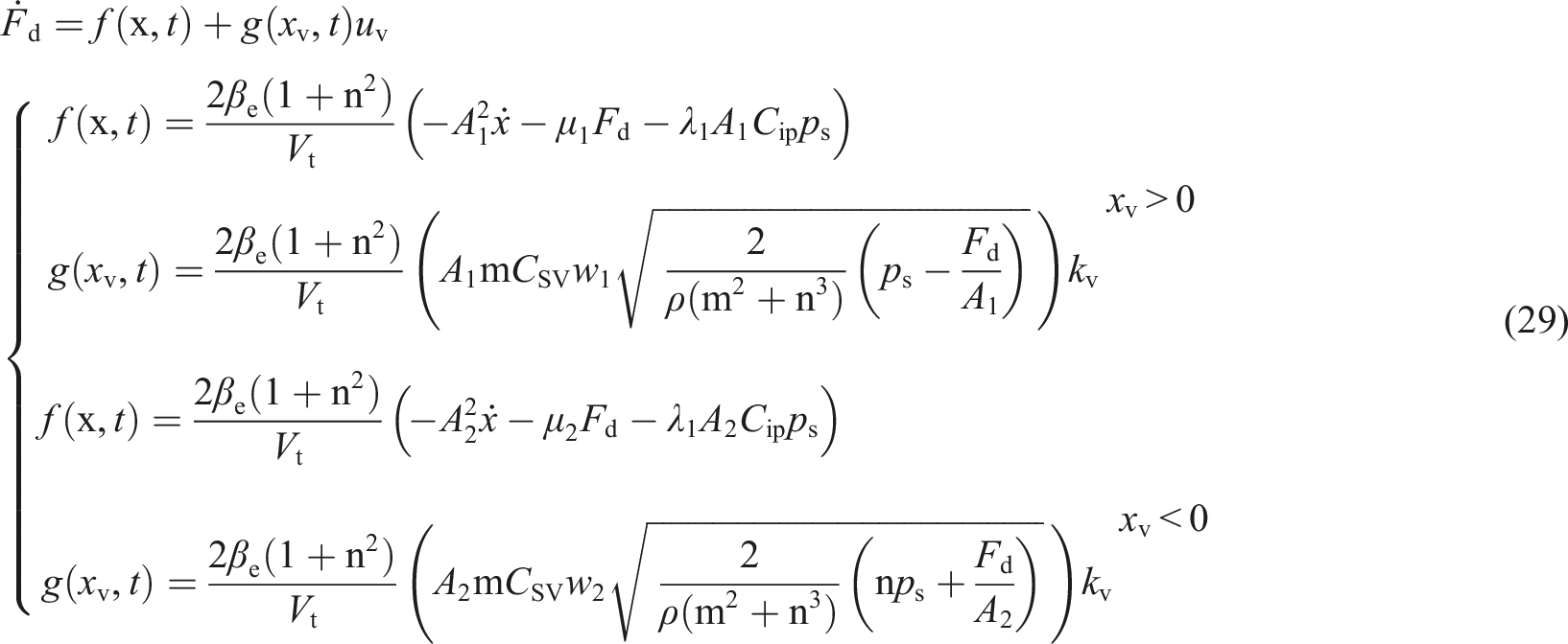
If the defining tracking error ef, ef = Fd- Fe, then the sliding surface is set to
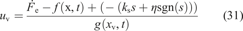
The adaptive law can be designed as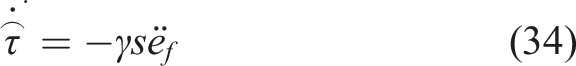
When equation (35) is satisfied, the designed controller is stable. When the error is in the sliding mode plane
The convergence rate of the system depends on ks. When vibration frequency beyond the limited value is detected, the controller is switched to the active hydraulic suspension mode. Prior to this, the accumulator absorption action mode can feasibly suppress for high-frequency vibration. Thus, a switch strategy is required to handle control situations. The condition that the vibration frequency is limited to a threshold must be satisfied to start the active vibration suppression control mode because it is difficult for proportional valve control to solve vibration at a high frequency. The hybrid sliding mode control strategy is illustrated in the flow chart in Figure 8. Flow chart for the hybrid sliding mode control strategy.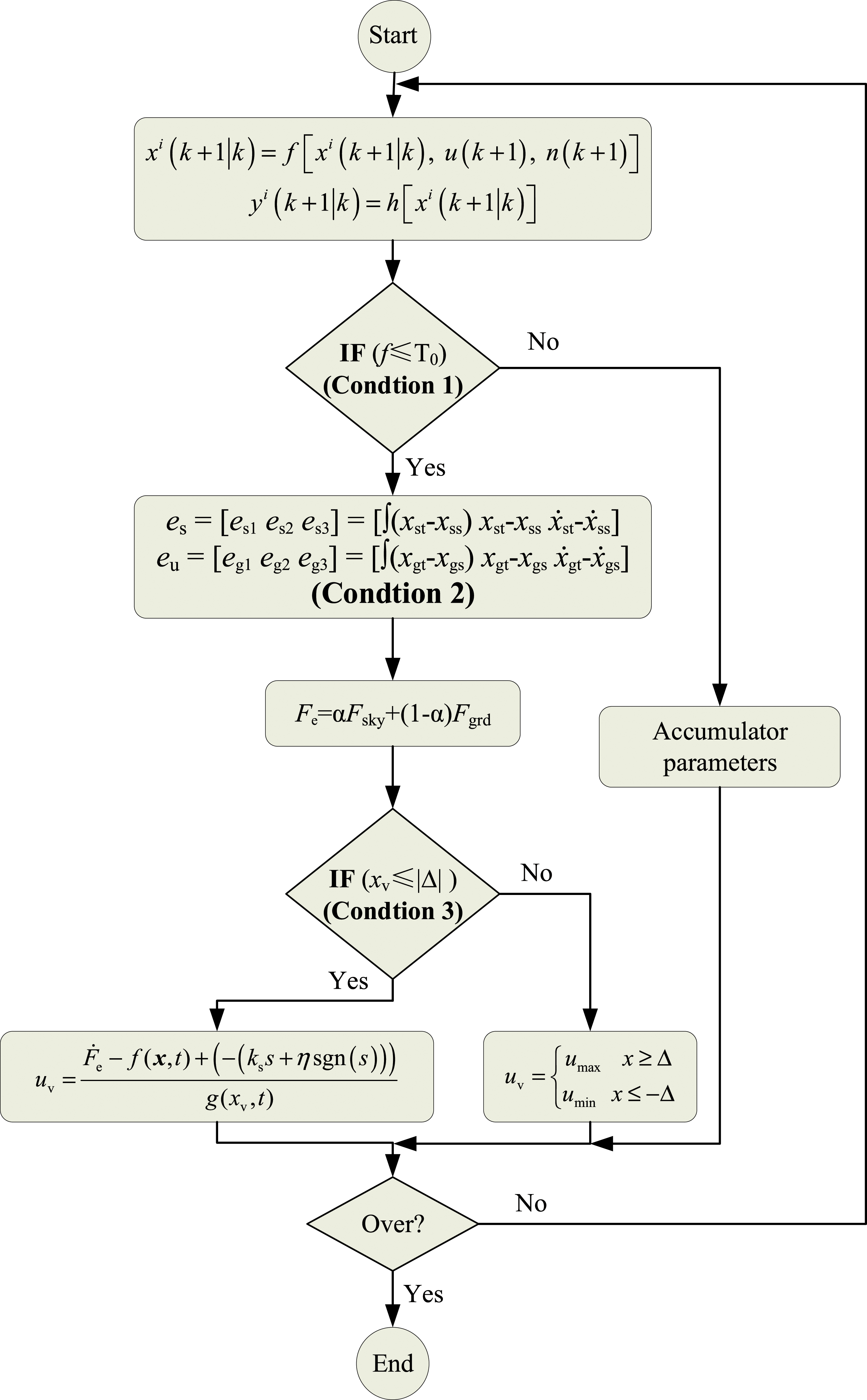
4. Simulation and experiments
The performance of the proposed hybrid sliding mode controller is estimated numerically and tested experimentally by simulating different working conditions. Random input excitation and varying step response are employed as conditions that a hydraulic suspension system typically encounters.
4.1. Simulation and analysis
We simulate step response and random input excitation to represent emergency vertical load increase and vibration suppression, respectively. The controller is constructed in MATLAB/Simulink, and the appropriate controller parameters are determined through repeat testing. By trial and error, the optimal parameters are acquired by considering the best control performances. The parameters of the hybrid sliding mode are λs1 = λg1 = 2.54, λs2 = λg2 = 44.38, ζmin = 0.14, and ζmax = 0.3. The integration time step is 1 millisecond, and the low-frequency error component is calculated using es and eu.
Figure 9(a) gives the random input excitation response of the hydraulic suspension system when the hybrid adjustment coefficient α = 0 is increased to α = 1. Figure 9(b) gives the result of the sprung mass acceleration power spectral density curve, showing that system vibration occurs once the excitation is input. However, under the controller, vibration is suppressed with a gradually decreasing amplitude and tends to reach the target. Figure 9(a) shows the different vibration absorption degrees, while the system resonance frequency is 1.35 Hz in Figure 9(b). The state estimated under random excitation after control: (a) Sprung mass acceleration and (b) sprung mass acceleration PSD.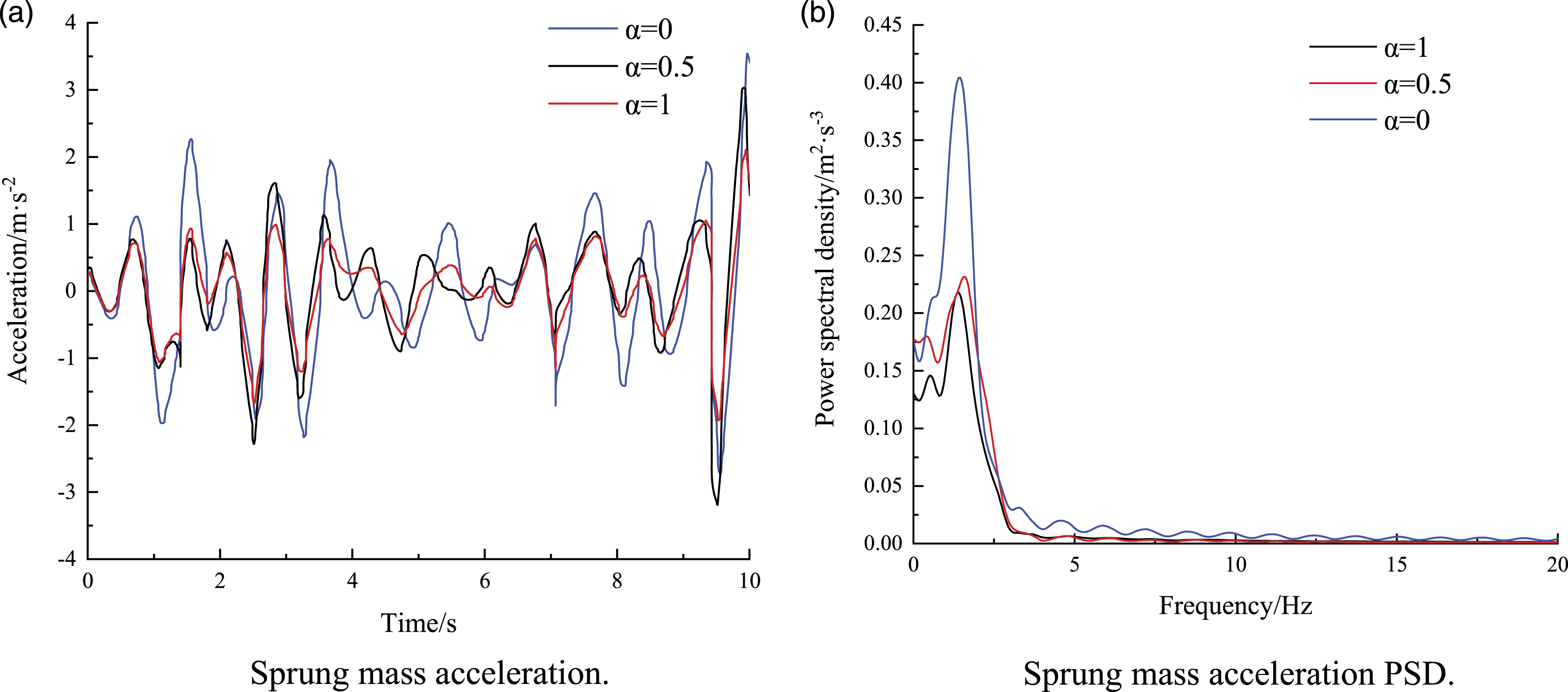
Figure 10(a) gives the estimated sprung mass displacement, when the target displacement increases by 0.05 m at 20 s and decreases by 0.05 m at 40 s. The simulation results of the integrated hybrid sliding mode control show that the actual displacement fluctuation is so low that the estimated state tracks the target state at the beginning control and the hybrid sliding mode controller works to reduce vibrations. Tracking response after control: (a) Sprung mass displacement and (b) sprung mass vibration acceleration.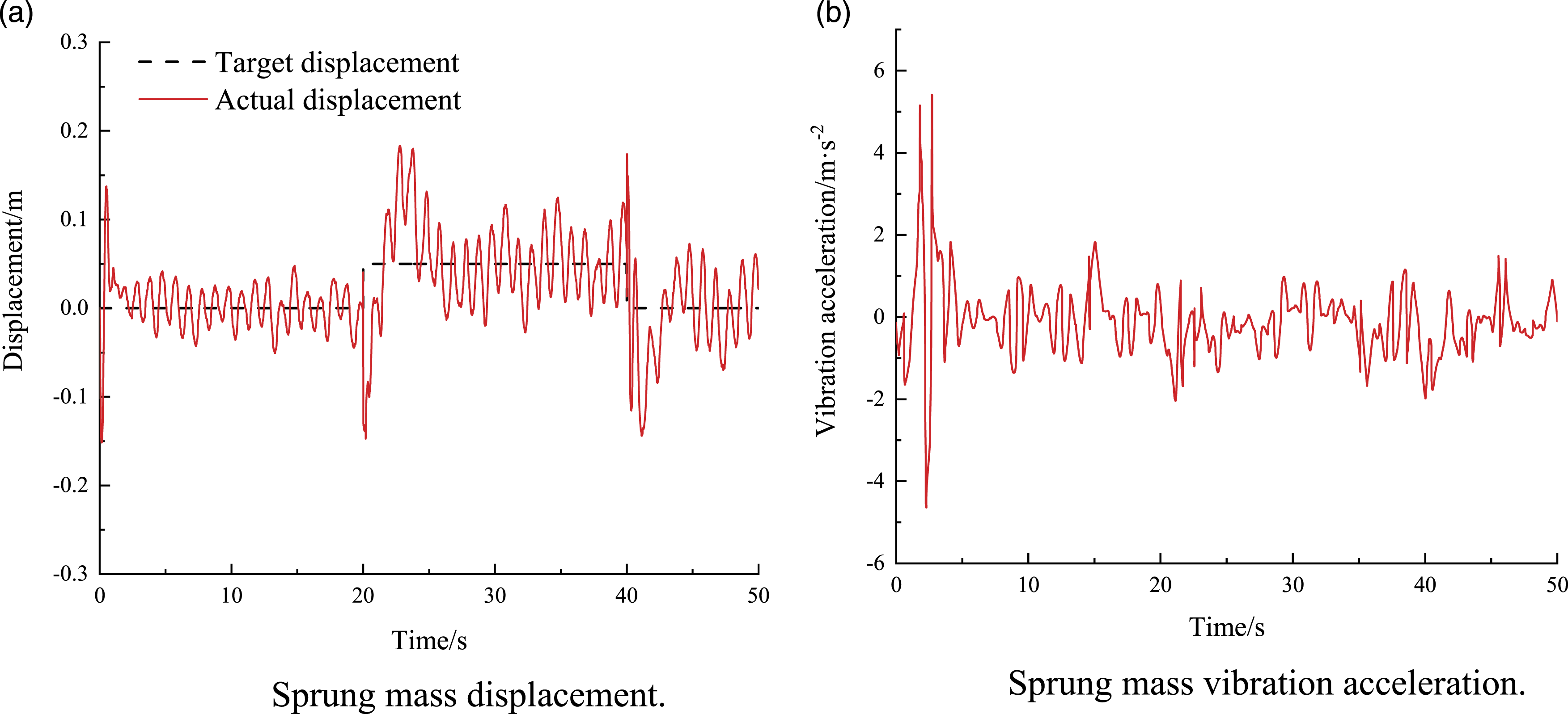
Figure 10(b) shows the result of vibration suppression. When the active adaptive hybrid sliding mode control is opened, the vibration suppression takes less than 3 s subject to the system response. Vibration suppression can be executed regardless if displacement increases or decreases. Thus, the control performance of the hydraulic suspension system is satisfied, and the effectiveness of the hybrid sliding mode control strategy is verified.
4.2. Experiments and results
Figure 11 shows the test bench built to validate the controller design. The proposed control algorithm is assembled using a real-time control unit (Huahai S2V3) that includes signal acquisition, control signal output, and a microcontrol chip. In this physical validation, a data acquisition computer is employed to collect sensor information from hydraulic suspension via the control unit. It is difficult to manipulate the output force between the vertical load and hydraulic piston without delay. In other words, it is practically impossible to design a hydraulic suspension system and controller that accommodate high-frequency nonlinearities by only changing Fd. In contrast, low-frequency vibrations can be easily handled by using active hydraulic suspension. Hydraulic suspension vibration test bench.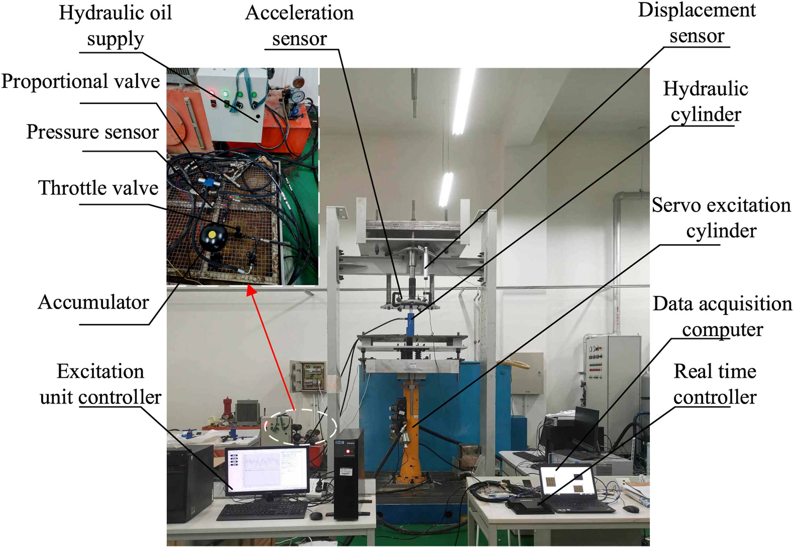
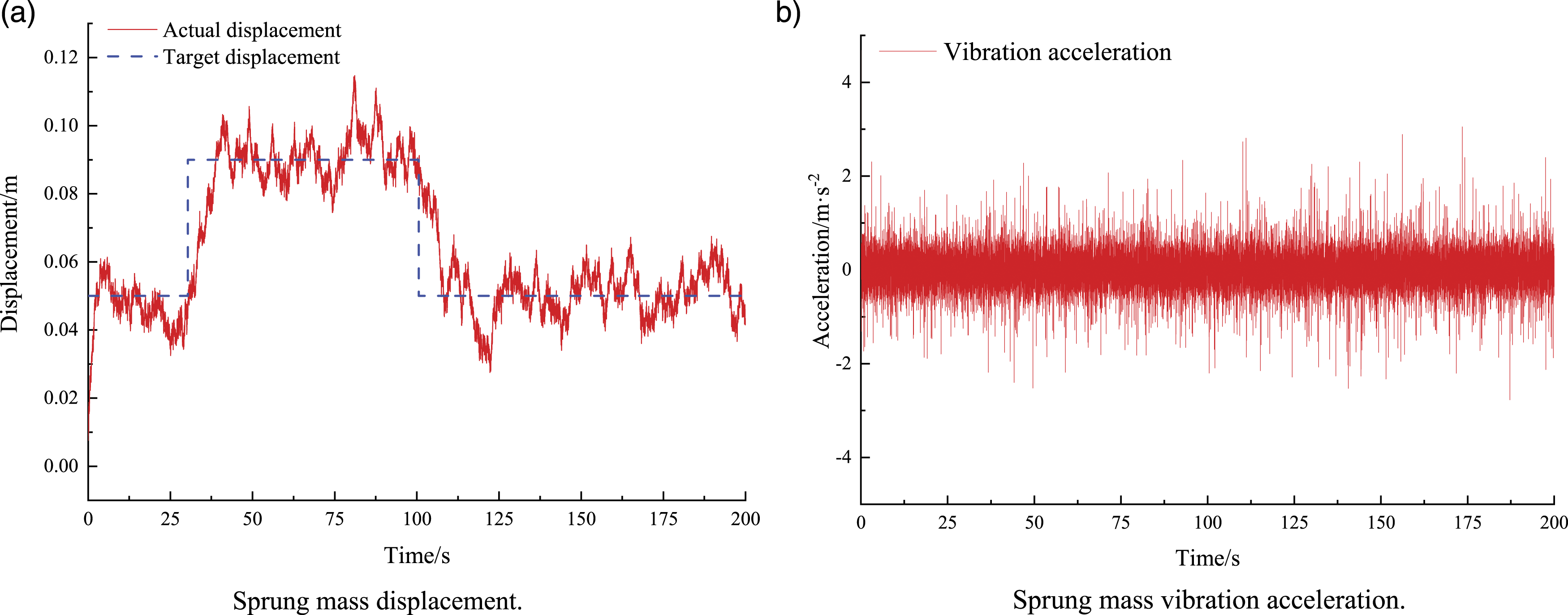
In order to analyze the control performance, the control results under the hybrid sliding mode algorithm with proportional valves are obtained. Figure 12 shows the frequency response of the active suspension simulation and test. Figure 13 shows the results of the proposed control method. Comparing the two sets of control results shows that the test result lags behind the simulation result because the hydraulic suspension system has a certain response time requirement. Additionally, vibration is suppressed in a certain range. In Figure 13(a) and 13(b), the target displacement increases by 0.04 m in 30 s and decreases by 0.04 m in 100 s. In this process, the actual displacement is adjusted for tracking the target displacement and the vibration is limited to less than 2.3 m/s2. Thus, the desired tracing performance is achieved, validating the effectiveness of the proposed control strategy. Therefore, the proposed method can obtain satisfactory control effectiveness according to both the simulation and the real test. Simulated frequency response of active control: (a) Sprung mass vibration acceleration and (b) sprung mass acceleration PSD. Experimental results under the proposed control method: (a) Sprung mass displacement and (b) sprung mass vibration acceleration.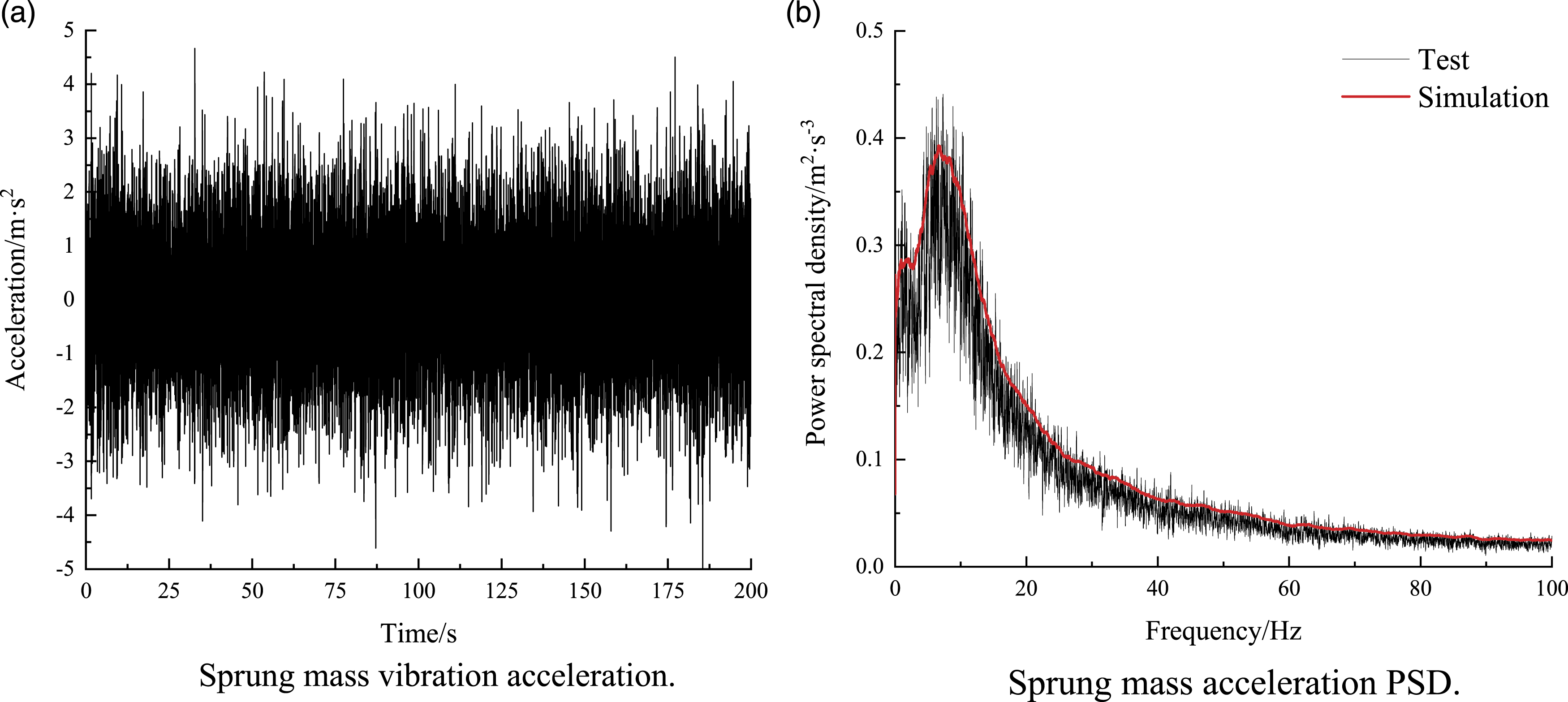
5. Conclusion
A hybrid sliding mode controller was developed to conduct vibration suppression in a hydraulic suspension system by facing input disturbance or changes in the physical environment. The controller included three parts: a hybrid sliding mode control algorithm based on the reference skyhook and groundhook model to regulate the reverse compensation expected force; an expected output force controller based on the sliding mode variable structure to suppress the vibration; and a logic rule to ensure that the two controllers obtained vibration suppression. A set of simulations and experiments were carried out to evaluate the feasibility and effectiveness of the proposed method, and a system was constructed to analyze the system characteristics and the controller design process. Results illustrated that the hybrid sliding mode controller could reduce the vibration of the system and track the target curve, which enhanced the robustness of the hydraulic suspension system. In the future, the proposed method could also be used to reduce disturbance in other nonlinear systems, and parallel controllers could be implemented to improve the system performance. On the basis of this concept, an advanced nonlinear time–frequency control method should be explored in subsequent research, along with a faster system response, to improve the real-time performance of the system.
Footnotes
Declaration of conflicting interests
The author(s) declared no potential conflicts of interest with respect to the research, authorship, and/or publication of this article.
Funding
The author(s) disclosed receipt of the following financial support for the research, authorship, and/or publication of this article: This paper has been partially supported by the research project: “Jiangsu Funding Program for Excellent Postdoctoral Talent (2022ZB517)” and “the Fundamental Research Funds for the Central Universities (2022QN1040).”