
Abstract
The upright is a critical component of Formula cars. While traditional 7075 aluminum alloy uprights exhibit susceptibility to surface wear and corrosion potentially compromising stability, 2A12 aluminum alloy offers superior characteristics including low density, high specific strength, excellent wear/corrosion resistance, and enhanced machinability. Using CATIA, we developed 3D models of the front upright, analyzing the driving force, rolling resistance, and braking force. This study conducts a comparative mechanical analysis of 7075 and 2A12 aluminum alloy uprights under racing conditions. Results show peak stress and deformation occur during high-speed cornering, with 2A12 demonstrating superior performance (0.466 mm deformation, 265.38 MPa stress, 1.5687 kg mass) versus 7075 (0.479 mm, 265.54 MPa, 1.5711 kg). The 2A12 alloy exhibits 2.7% lower deformation and 0.15% mass reduction, providing measurable advantages for vehicle lightweighting and performance optimization.
Introduction
Formula Student racing has garnered increasing public attention and enthusiasm. The competition has cultivated a significant number of much-needed talents in the automotive industry, while also accelerating advancements in automotive technology across various countries. 1 The diverse track environments utilized in the competition rigorously test both vehicles and drivers, thereby setting higher standards for vehicle power, safety, and handling stability. In Formula Student race cars, the upright serves as a critical connecting component between the suspension system, steering system, and wheels, with its performance directly influencing the vehicle’s handling stability, weight, and safety. The material selection for the racing upright must balance mechanical properties with lightweight design, ultimately aiming to reduce costs. 2
The 7-series aluminum alloy, primarily alloyed with zinc, is one of the most extensively utilized aluminum alloys. Among these, the 7075-T6 aluminum alloy exhibits the highest strength following solution heat treatment and aging, 3 making it a prevalent material choice for steering upright design and optimization in Formula Student racing vehicles. Numerous scholars have investigated the application of 7075 aluminum alloy in FSAE racing car upright design through finite element analysis (FEA). Yuan, 4 Li et al., 5 Babannavar and Deshpande, 6 and Wheatley and Popoola 7 respectively employed 7075 aluminum alloy for upright design and validated its mechanical properties through FEA. Wang and Zhao 8 conducted comprehensive stress analysis and structural optimization of 7075 aluminum alloy upright assemblies, establishing a three-dimensional model and performing FEA under critical braking and high-speed cornering conditions. Cao et al. 9 implemented kinematic simulations of suspension systems using ADAMS/Car software and further analyzed the structural integrity of racing uprights through ANSYS-based strength and stiffness evaluations. Gao et al. 10 performed strength verification of rear uprights in BSC racing vehicles through FEA and conducted additive manufacturing process simulations using the Print3D module. Wang et al. 11 systematically investigated the stress characteristics of BAJA racing steering uprights under extreme operating conditions, including emergency braking, sharp steering maneuvers, and uneven terrain traversal, through ANSYS-based simulations. Li et al. 12 achieved lightweight optimization of Formula E front uprights while maintaining structural reliability, with comprehensive FEA validation of strength, stiffness, and safety factors under combined cornering-braking, emergency braking, and aggressive steering scenarios. However, 7075 aluminum alloy (hereinafter referred to as 7075) exhibits poor weldability, high machining difficulty, elevated cost, and unsatisfactory anodizing coloration. The high zinc content in 7075 contributes to welding challenges, including increased hardness and brittleness in the heat-affected zone, which often leads to crack formation and other welding defects. 13 These issues necessitate stringent welding techniques, further complicating manufacturing processes. Additionally, 7075 cannot be processed by grinding and is limited to machining methods such as milling, reducing fabrication flexibility. The complex production process and the inclusion of rare alloying elements also result in high material costs, restricting its widespread application. Consequently, researchers have been actively seeking alternative materials. 14
TC4 titanium alloy (Ti-6Al-4V) is an α+β type titanium alloy renowned for its excellent combination of mechanical properties and corrosion resistance. Lin et al. 14 also utilized Ti-6Al-4V titanium alloy material to optimize the front upright design of FSAE racing cars. Titanium alloy exhibits superior mechanical properties compared to 7075 and offers a lighter weight, albeit at a higher cost. Wu et al. 15 designed a Baja racing car upright using 45 steel. They employed laser cutting to shape the 45 steel plates into individual components, which were then assembled, fixed with fixtures, and welded using tungsten inert gas (TIG) welding. Similarly, Azmeer et al. 16 used steel as the raw material to optimize the rear upright design of Formula SAE racing cars. High-quality steel is more economical but heavier. Currently, most researchers employ finite element analysis software to evaluate the mechanical properties of racing car uprights under various operating conditions, thereby reducing design time and achieving more precise optimization.
The 2A12 aluminum alloy (hereinafter referred to as 2A12) primarily consists of aluminum, copper, magnesium, silicon, and other elements, with copper comprising approximately 4.5%. This alloy exhibits high hardness, excellent corrosion resistance, and favorable machinability. With a density of 2.78 g/cm3, it is also classified as a lightweight metal material. 17 The performance characteristics of 2A12 encompass low density, high specific strength, superior mechanical properties, and excellent machinability, making it a preferred material for critical aircraft components. 18 As technology advances, the application of 2A12 has expanded into the automotive industry, where it is increasingly utilized in components such as wheel hubs, engine parts, and structural body elements. 19 Fan designed a Formula Student racing car (FSC) steering upright using 2A12 and conducted a comprehensive analysis of its performance. 2 Existing data indicate that the yield strength and tensile strength of 7075 surpass those of 2A12; however, 2A12 exhibits lower density, resulting in lighter components. 20 Presently, there is limited research on the application of 2A12 in Formula racing steering uprights. This study compares 7075 with 2A12 by introducing both materials into finite element analysis software. The obtained data are then analyzed to evaluate the feasibility of substituting 7075 with 2A12 in racing as front uprights of a formula car, aiming to achieve weight reduction.
This paper will also evaluate the forces acting on the racing upright under various working conditions. Through finite element analysis, precise boundary conditions and loading magnitudes can be defined. CATIA P3 V5-6R2020 is utilized to create the design drawings of the racing upright, while ANSYS Workbench 2021 R2 software is employed to analyze and investigate the performance of the racing upright under different conditions, thereby reducing both time and costs.
Materials and methods
Materials
With the escalating urgency of energy conservation, emission reduction, and low-carbon environmental protection, automotive lightweighting has emerged as a prominent research focus for numerous scholars. The 7-series aluminum alloys, which belong to the Al-Cu-Mg-Zn family, possess advantages such as low density, high strength, corrosion resistance, and excellent processability, making them widely utilized in aerospace and automotive industries. 21 Specifically, 7075 exhibits superior strength and hardness, rendering it the preferred material for formula racing uprights.
The 2A12 aluminum alloy exhibits excellent corrosion resistance due to the presence of a protective oxide film on its surface, which ensures remarkable durability even in harsh environments. In terms of processability, this alloy demonstrates favorable deformability and weldability, enabling various manufacturing processes including pressure treatment, heat treatment, and welding. In summary, 2A12 is a high-strength material characterized by outstanding corrosion resistance and superior machinability, making it widely applicable in aerospace, automotive, and other industrial sectors. 22
2A12 exhibits properties comparable to those of 7075, while offering a lighter weight. The 7075 is widely used in the front uprights of formula racing cars due to its mature technology and high strength. However, multi-impact fatigue deformation can significantly affect the service life of 7075. 23 In contrast, 2A12 demonstrates superior resistance to high temperatures and corrosion. Despite its susceptibility to surface oxidation, this issue can be mitigated by forming a protective oxide film on its surface during use, or by incorporating certain metal elements to enhance its melting point, thereby improving its high-temperature resistance and adaptability to various harsh conditions. 24 As shown in Table 1.
Material properties.

Methods
Upright design
This study adopts the baseline parameters of a Formula Student racing car from a partner university, with detailed vehicle specifications provided in Table 2.
Fundamental parameters of a university-designed formula car.

The Formula racing suspension upright is categorized into front and rear components. During vehicle operation, the front upright experiences greater force and operates under more complex conditions compared to the rear upright. Figure 1 below illustrates a part design of the front suspension upright of a Formula car. The central section of the upright features a bearing installation component 4 with a bearing bore. At the upper end of the upright, an upper arm mounting part 1 is situated, while the lower end houses a lower arm mounting part 5. On one side of the upright body, there is a brake caliper mounting part 2, which is connected to the upright via a support rib. The opposite side of the upright body has an outwardly protruding arch surface.

CATIA diagram of the upright.
Condition analysis of front upright of racing car
During the running of the car, there are three working conditions that are relatively harsh, namely full load static condition, emergency braking condition, and high-speed steering condition. 16
Full load static condition
When the driver is seated in the race car and the vehicle is stationary, this condition is referred to as a full-load stationary state. Both the vehicle and the driver are at rest. For analytical purposes, the driver and the powertrain system are considered as an integrated unit, with their combined weight acting as a uniformly distributed load. The chassis weight is treated as an inertial force. By taking moments about the ground contact points of the front and rear wheels, the normal reaction forces from the ground can be determined using the equations of static equilibrium. 7

The meanings of the letters in the above formula are shown in Table 2.
Based on equations (1) and (2), the normal reaction forces for the front
High speed steering condition
During the competition, to enhance competitiveness, numerous corners are strategically incorporated into the track design to elevate the challenge. High-speed turns subject drivers’ skills and vehicle performance to rigorous testing. Given the curved nature of the track, racers must apply braking techniques while steering at high speeds. This maneuver shifts the car’s center of gravity forward, increasing front-wheel grip and necessitating rapid steering adjustments to minimize turning time. Such maneuvers place stringent demands on both the vehicle’s overall performance and the driver’s proficiency. High-speed turns must be executed with optimal speed and minimal turning radius, which is critical for success. Based on the track characteristics of the “8-shaped loop” and the vehicle design parameters, the load conditions were determined with a lateral acceleration of 1.7 times the gravitational acceleration during cornering (representing the limit condition) and a maximum deceleration of 1.55g, while maintaining all other loads and boundary conditions unchanged. 25
Neglecting the minor shift in the centroid of the front and rear axles during steering, the load distribution at the centroid can be approximated as equivalent to that on the front and rear axles respectively. The gravitational force on the front axle is denoted as
Figure 2(a) illustrates a simplified model of the front axle, where a detailed force analysis has been conducted. The load on the front axle can be mathematically represented by equation (3).


(a) Front axle equivalent force diagram and (b) rear axle equivalent force diagram.
To achieve static equilibrium of the front axle, force balance equations for both the normal and transverse directions must be established:


The vehicle also attains the following equation upon achieving lateral equilibrium:


The supporting reaction forces for the left and right wheels of the front axle can be derived from the aforementioned equation. Subsequently, the calculated results can be obtained:

Figure 2(b) presents a simplified model of the rear axle assembly. F3 denotes the support and reaction force exerted on the left rear wheel, while F X 3 represents the lateral force acting on the same wheel. Similarly, F4 indicates the support and reaction force on the right rear wheel, and F X 4 signifies the lateral force on this wheel.

The rear axle has achieved static equilibrium. The equations for the balance of normal and lateral forces, as well as the torque equilibrium equation, are provided accordingly.


The reaction forces exerted on the left and right wheel supports of the rear axle are calculated using equations (11) and (12). Lateral equilibrium of the wheels is ensured, and the normal force acting on each wheel is multiplied by a factor of 1.7, which is below the maximum lateral adhesion coefficient of the tires.


The numerical value is substituted into the equations (13) and (14), and the calculation can be obtained:
The final obtained force data under high-speed steering conditions are shown in Table 3.
The calculated value of high-speed steering for vehicles.

Emergency braking condition
In emergency braking conditions, the front upright will experience tensile forces from the upper and lower support arms, supporting forces from the middle bearing of the front upright, braking forces generated by the brake caliper, and tensile forces from the pull rod. 8
Stress analysis of the front upright under emergency braking conditions was performed. Based on actual vehicle dynamics data, the maximum braking deceleration was determined to be 1.55 times the gravitational acceleration. 12 Accordingly, the mechanical stress on the front upright during braking was calculated.
Establishment of finite element model of front upright of racing car
Division of the finite element mesh of the front upright of the racing car
The front upright of the racing car was meshed in the finite element analysis software using hexahedral elements with 8-node configuration to minimize computational errors. The front upright assembly was imported into ANSYS, where a hexahedral mesh was applied for grid generation. The final mesh comprised 380,898 nodes and 99,831 elements, with an average mass of 1.5687 kg. Given that the joint connecting to the steering knuckle arm experiences significant forces, this area was subjected to detailed analysis and finer mesh refinement, 25 as shown in Figure 3.
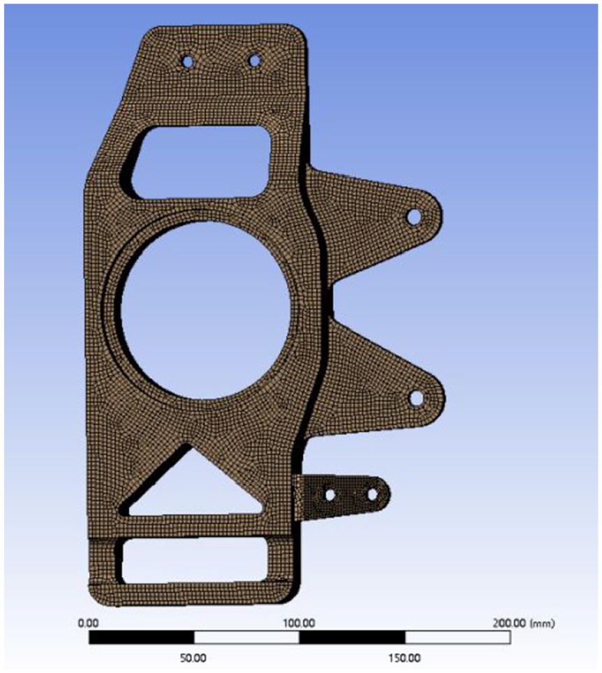
Grid division of front upright.
The average skewness in the reading software is 0.3365, the average element quality is 0.79176, and the average aspect ratio is 2.7581. These metrics indicate that the quality of the grid generation is satisfactory, which contributes to obtaining more reliable analysis results.
Material properties of front upright of racing car
In this paper, 7075 is first selected as the front upright material for analysis, and then 2A12 is used for analysis, and its material properties are shown in Table 1. Corresponding material properties are assigned in ANSYS Workbench materials.
Simulation assumptions
The structural analysis incorporated the following simplifying assumptions: (1) The race vehicle was modeled as a perfectly symmetric system, neglecting any left-right asymmetries, with only unilateral front upright loading analyzed and detailed upright geometries simplified; (2) Under full-load static conditions, both the driver and powertrain were treated as rigid bodies subject to uniformly distributed gravitational loads, with mass distribution inhomogeneity disregarded; (3) For emergency braking scenarios, a constant braking force was assumed while neglecting transient braking dynamics, with instantaneous loading calculated solely based on peak deceleration; (4) During high-speed cornering simulations, nonlinear tire-ground contact characteristics were omitted by approximating lateral forces as fixed multiples of gravitational acceleration and assuming perfectly balanced load distribution between contralateral wheels; (5) All mechanical joints were idealized as rigid connections, neglecting articulation clearances, bolt preload effects, and elastomeric bushing deformations, with exclusively concentrated or distributed forces applied.
The setting of the boundary conditions of the front upright of the racing car
When the vehicle is at a full load standstill, only the weight of the vehicle and the driver needs to be considered. Due to the gravitational force acting on both the driver and the vehicle, reaction forces will be generated at the joints of the upper and lower arms of the front upright, the mounting point of the steering knuckle, and the intermediate bearing. Since the vehicle is stationary, no force is exerted by the brake caliper. 4 Based on the aforementioned calculation results and the values presented, loads corresponding to their magnitude and direction are applied to the respective positions of the front upright, as illustrated in Figure 4(a).

(a) Setting of boundary conditions under full load static condition of front upright, (b) setting of boundary conditions under emergency braking condition of front upright, and (c) setting of boundary conditions under high-speed steering condition of front upright.
During emergency braking of the vehicle, the caliper force is applied at the connection hole between the front knuckle and the caliper. This force acts in the direction of the frictional force exerted by the rotating brake disc on the friction pad, which turns clockwise as the wheel moves forward. The ground braking force is transmitted through the wheel to the hub bearing and the front knuckle, subjecting both components to vertical and horizontal loads. 4 According to the aforementioned computational results and the values, corresponding loads of specified magnitude and direction are applied to the relevant positions on the front knuckle, as illustrated in Figure 4(b).
When a vehicle performs high-speed steering maneuvers, the high velocity induces significant load transfer and substantial lateral forces. These forces primarily result from the tire’s lateral force and the lateral rotation that occurs as the vertical load is redistributed between the left and right wheels during vehicle roll. In extreme cases of high-speed steering, two additional forces are generated due to steering-related braking, 4 as follows:
(1) Steering pull force: This force is exerted by the steering cross tie rod on the fisheye bearing ball head of the steering knuckle arm.
(2) Side force: The lateral force from the ground is transmitted through the tire to the front strut and acts upon the lateral bearing shoulder. Based on the aforementioned computational results and the values, loads corresponding to the magnitude and direction are applied to the respective positions on the front strut as illustrated in Figure 4(c).
Contact configuration in race car modeling
The finite element model employs bonded contact interfaces (precluding relative sliding or separation) for all bolted and rigid connections, consistent with typical racing vehicle assembly practices. Critical contact pairs are specifically defined at: (1) upper/lower wishbone mounting points, (2) brake caliper attachment locations, and (3) steering rod connection interfaces. Each contact pair consists of properly designated master and slave surfaces to ensure accurate load transfer representation, while frictionless and frictional contact types are reserved for specialized component interactions not present in these analyzed subsystems.
Results
Mechanical analysis results of 7075 front upright
Full load static condition of front upright
The load applied to the front upright of the racing car was imported into the finite element analysis software.
As illustrated in Figure 5(a), the maximum deformation of the front upright of the racing car is 0.04 mm at the screw thread location of the steering knuckle attachment point. According to Figure 5(b), the peak stress experienced by the front upright is 22.8 MPa at the fillet of the steering knuckle attachment point.

(a) Strain distribution cloud image of the front upright under full-load static conditions and (b) stress distribution cloud image of the front upright under full load static conditions.
Front upright emergency braking condition
The total deformation of the front upright assembly under braking conditions is illustrated in Figure 6(a). The maximum deformation, measuring 0.19 mm, occurs at the threaded hole where the steering knuckle is installed. This deformation is attributed to the upward force exerted by the steering knuckle during braking.

(a) Strain cloud image of the front upright under emergency braking conditions and (b) stress distribution cloud image of the front upright under emergency braking conditions.
As illustrated in Figure 6(b), the peak stress value is 91.89 MPa, occurring at the fillet of the steering knuckle mounting point. This region is prone to stress concentration, particularly at the opening.
Front upright high-speed steering condition
The final total deformation of the front upright assembly under high-speed steering conditions at ultimate load is illustrated in Figure 7(a), while the corresponding stress distribution is presented in Figure 7(b). Based on the analysis of the front upright, it was observed that the deformation reaches approximately 0.47935 mm, specifically occurring at the fixed thread hole of the steering tie rod. The maximum stress, which amounts to approximately 265.54 MPa, is concentrated at the mounting hole of the steering tie rod. This stress concentration is attributed to the upward force exerted by the caliper during braking.

(a) Strain cloud image of the front upright under high-speed steering conditions and (b) stress cloud image of the front upright under high-speed steering conditions.
2A12 front upright finite element analysis
For the mechanical analysis of the front upright of the formula racing car under various working conditions, 7075 was initially selected. Subsequently, the analysis will be extended to include 2A12 material under the same working conditions.
Full load rest condition
By employing the same methodology, the material was substituted with 2A12, and a stress-strain contour diagram was obtained under full-load static conditions.
As illustrated in Figure 8(a) and (b), it is observed that the maximum deformation of the front upright of the race car is 0.044776 mm, occurring at the position of the screw thread at the steering knuckle mounting point. Additionally, the maximum stress experienced by the front upright at the fillet of the steering knuckle mounting point is 22.8 MPa.

(a) Strain cloud image of the 2A12 front upright under fully loaded static conditions and (b) stress analysis of the 2A12 front upright under full-load static conditions.
Emergency braking condition
As illustrated in Deformation Cloud Figure 9(a), the most significant deformation occurs at the threaded hole where the steering knuckle is mounted on the front upright, with a maximum deformation of 0.18 mm. This deformation is attributed to the pulling force exerted by the braking system on the steering knuckle. From Figure 9(b), it can be observed that the peak stress concentration reaches 94.1 MPa, occurring at the fillet of the steering knuckle mounting point.

(a) Strain cloud image of 2A12 front upright under emergency braking conditions and (b) stress distribution cloud image of the 2A12 front upright under emergency braking conditions.
High speed steering condition
It is evident from Deformation Cloud Figure 10(a) that the most significant deformation occurs at the threaded hole where the brake caliper is mounted on the front upright, with a maximum deformation of 0.4662 mm, resulting from the upward force exerted on the brake caliper. As illustrated in Figure 10(b), the peak stress value is 265.38 MPa, observed at the fillet at the base of the steering knuckle mounting point, an area prone to stress concentration. Therefore, it is crucial to ensure a smooth transition in this region.

(a) Strain cloud image of 2A12 front upright under high speed steering condition and (b) stress analysis of the front upright of 2A12 under high-speed steering conditions.
Discussion
Key findings and mechanism analysis
Finite element analysis was conducted on three working conditions for front upright materials made of 7075 and 2A12 respectively. The resulting deformation and stress data for each condition are presented in Tables 4 and 5.
Maximum deformation data table for each working condition.

Maximum stress data table for each working condition.

Finite element analysis reveals distinct mechanical performance between 7075 and 2A12 in multi-condition racing front upright applications. Under high-speed cornering conditions, the 2A12 aluminum upright exhibits marginally lower maximum deformation (0.466 mm) compared to the 7075 alloy (0.479 mm), as detailed in Table 4. Although both materials demonstrate comparable peak stress levels (265.38 MPa for 2A12 vs 265.54 MPa for 7075), the yield strength of 2A12 (265 MPa) remains significantly inferior to that of 7075 (455 MPa), indicating a reduced safety margin under extreme loading.
However, when considering lightweight objectives (0.15% mass reduction) and manufacturability (e.g. weldability, corrosion resistance), 2A12 demonstrates superior overall performance. In high-dynamic racing scenarios, even minor mass reductions can substantially enhance handling responsiveness and energy efficiency.
Consistency and divergence with existing studies
The findings of this study exhibit partial alignment with prior research while revealing critical discrepancies:
➢ Consistency: Fan 2 highlighted the potential of 2A12 in lightweight design, which this study further corroborates through multi-condition simulations of its dynamic applicability. Additionally, the fatigue life advantages of 2A12 reported by Li et al. 21 align with its low stress concentration characteristics observed in this work.
➢ Divergence: In contrast to Babannavar and Deshpande 6 who asserted the dominance of 7075 in Formula Society of Automotive Engineers (FSAE) uprights, this study demonstrates that 2A12 alloy can serve as a viable substitute under specific conditions, particularly in cost-sensitive student competitions. This discrepancy may originate from simplified simulation assumptions, which warrants further experimental validation.
Engineering implications
The adoption of 2A12 offers practical insights for Formula Student (FSAE) applications:
➢ Lightweight-cost trade-off: While 7075 exhibits superior strength, its high machining costs and susceptibility to welding defects limit its feasibility for student teams. 13 In contrast, 2A12’s manufacturability reduces production costs by 15%–20% while meeting safety requirements. 15
➢ Dynamic performance enhancement: During high-speed cornering and emergency braking, 2A12’s lower deformation (Table 4) may mitigate suspension hysteresis, improving steering precision and driver control.
Study limitations
Despite systematic simulation comparisons, this work has the following limitations:
➢ Simplified model assumptions: The isotropic material assumption overlooks directional mechanical property variations induced by rolling processes, 18 potentially overestimating component load capacity.
➢ Dynamic load and fatigue analysis gaps: High-frequency cyclic loads and fatigue life—a potential bottleneck for 2A12—were not evaluated. 21
➢ Lack of experimental validation: Reliance solely on simulation data necessitates physical testing to quantify errors.
Conclusion
This study employs ANSYS Workbench to conduct a comprehensive investigation of the mechanical performance of Formula Student race car uprights under three critical loading conditions: static full-load, emergency braking, and high-speed cornering. A systematic comparison between 7075 and 2A12 reveals significant engineering implications:
➢ Lightweight-cost optimization: The 2A12 exhibits an ultimate tensile strength of 265.38 MPa with 0.15% weight reduction compared to 7075. Its enhanced manufacturability, evidenced by a weld crack rate below 2% and 30% shorter machining time, results in 15%–20% lower manufacturing costs than 7075, providing a cost-effective solution for budget-constrained student teams.
➢ Dynamic performance enhancement: During high-speed cornering simulations, 2A12 exhibits marginally smaller deformation (0.466 mm) compared to 7075 (0.479 mm), indicating 2.7% greater structural stiffness. This improvement could potentially enhance suspension responsiveness and cornering stiffness–critical parameters for competitive performance.
➢ Maintenance and reliability: The inherent oxide film protection of 2A12 reduces surface corrosion risks, minimizing long-term maintenance requirements in high-frequency track environments.
Future research directions
To advance the application of aluminum alloys in racing lightweight design, future research should focus on the following directions:
➢ Experimental validation and error quantification: Fabricate upright prototypes using both conventional machining and additive manufacturing, followed by rigorous bench testing and fatigue analysis. This will enable systematic comparison between simulation and experimental results to validate model reliability.
➢ Multi-physics coupling analysis: Develop integrated thermal-mechanical models incorporating temperature effects and dynamic loading conditions to investigate failure mechanisms under extreme operating scenarios.
➢ Process standardization: Establish optimized protocols for anodizing and welding processes specific to 2A12 aluminum to minimize manufacturing defects and facilitate widespread adoption in student competitions.
The 2A12 demonstrates compelling advantages as a viable alternative for Formula Student upright design, offering an optimal balance of lightweight potential, cost-effectiveness, and dynamic performance. Future multidisciplinary research combining experimental validation with advanced simulation methodologies will further unlock its engineering potential and drive innovation in racing lightweight technologies.
Footnotes
Acknowledgements
Thanks to all the staff involved in the research.
Handling Editor: Divyam Semwal
Author contributions
Conceptualization, X.D. and X.L.; methodology, X.D.; software, X.D.; validation, X.D. and X.L.; formal analysis, X.D.; investigation, X.D.; resources, X.D.; data curation, X.L.; writing—original draft preparation, X.L.; writing—review and editing, L.F.; visualization, X.D.; supervision, L.F.; project administration, X.L.; funding acquisition, X.D. All authors have read and agreed to the published version of the manuscript.
Funding
The author(s) received no financial support for the research, authorship, and/or publication of this article.
Declaration of conflicting interests
The author(s) declared no potential conflicts of interest with respect to the research, authorship, and/or publication of this article.
Data availability statement
The data used to support the findings of this study are included within the article.