
Abstract
To meet the urgent market need for implementation of various heavy-load operations within complex and restricted underground environments, this paper proposes a new scientific structural development scheme for underground heavy-load robot. The scheme combines topology optimization and modular scale synthesis to achieve the optimal configuration for underground heavy-load robot. Firstly, orienting to the specific working environment and design requirements, a feasible configuration was deduced by the configuration synthesis method. Then, the topology optimization was carried out to output a new stable configuration for underground heavy-load robot with good flexibility and stability. Secondly, the modular design idea was applied to realize the optimal scale synthesis and function expansion of underground heavy-load robot. Finally, based on the kinematic analysis model, a reasonable and effective performance evaluation system was established to verify the performance of underground heavy-load robot. Simulation and experimental results indicated that the underground heavy-load robot developed in this paper had a more reasonable structure and more comprehensive functions. It can fully meet the design requirements of flexible operation and high carrying capacity in the confined underground space. The research in this paper provides new ideas for the structural development of heavy-load robot, effectively enhances the design efficiency of spatial multi-freedom degree industrial robot, and lays a foundation for the coordinated control of modern intelligent robots.
Keywords
Introduction
Although all kinds of heavy-load industrial robots have been relatively mature and can carry out heavy-load operations such as handling, stacking and assembly, 1 with the increasing trend of deep mining year by year, the underground temperature rises, ground pressure increases, rock bursts occur frequently and the risk of thermal damage grows. 2 As a result, the existing heavy-load robots cannot meet the requirement of operating multi-heavy-load tasks in complex underground non-structural environment. All these factors increase the difficulties of underground mining. Especially in the 1 km mining distance of heading face, due to lack of intelligent mining machinery, all kinds of heavy-load operations such as lifting, handling, supporting are completed manually, which leads to the low work efficiency and unpredictable disasters. Therefore, the design and development of a new type of underground heavy-load robot have become an urgent issue for the development of intelligent coal-mining machinery.
The reasonable and feasible structural design is the most important factor in ensuring the performance of robots: Wei et al. 3 proposed an analytic hierarchy process based on finite element analysis method to optimize the structure of heavy-load palliating robot and improve the dynamic performance of robotic system. Pagoli et al. 4 designed a high-strength pneumatic finger configuration through joints topology optimization. Liu et al. 5 studied a novel hierarchical framework targeting autonomous exploration and inspection for high-DOF robots. Dong et al. 6 presented a topology optimization framework based on bi-directional evolutionary structural optimization method for designing SMA robot structures. Dalklint et al. 7 used simultaneous shape and topology optimization to design pressure-activated inflatable soft robots. Hu et al. 8 designed of a re-configurable robot manipulator by using modular layouts methods, which can perform many given tasks. Guan et al. 9 studied a meta-module motion design approach for homogeneous modular robotic systems in self-configuration to remove the locomotion gap between single modular and reconfiguration of whole robot system. Wu et al. 10 designed a 9-DOF redundant series-parallel hybrid robot configuration schemes. Moreover, the idea of modular design is also introduced: Levin and Degani 11 constructed a manipulator module and an end gripper module, to assemble the corresponding manipulator according to different demanding tasks. Feng et al. 12 divided the robot into different modules and designed the common standard interface between each module, which greatly improved the design efficiency of robots. Zhao 13 used the operational ability, gravity to be overcome and working space as the indexes, to study the configuration optimization of mechanical arm. Kang and James 14 proposed a multi-objective optimization method for reconfiguration modular robot. Dai et al. 15 developed a new low-cost and multi-functional modular robot platform. Caasenbrood et al. 16 constructed module library of robot and realized automatic assembly between each module.
Based on the above studies, most of the structural design of robots is carried out according to specific task requirements. Robots with fixed structural configurations have difficulty meeting the actual production needs of performing multiple operations in complex working conditions and cannot adapt to the rapidly changing market demands.17,18 Furthermore, most researches mainly focus on structural design of robots, and there is a lack of coordination between structural design and scale synthesis of entire robots. This leads to the functions of developed robots deviating from actual requirements. Moreover, the research on the combination of hydraulic technology and intelligent industrial heavy-load robot technology is scarce, which results in the developed industrial heavy-load robots being unsuitable for underground conditions. Therefore, oriented to the design tasks, this paper proposes a new method for the structural development of underground heavy-load robot by combining topology optimization of configurations and modular scale implementation. In addition, a reasonable evaluation of the system performance of underground heavy-load robot is carried out by constructing a system performance evaluation system. The process of this paper is shown in Figure 1.

Structure development and design process of underground heavy-load robot.
Structural optimal design and implementation of underground heavy-load robot
To obtain the reliable structure of underground heavy-load robot, this paper proposes a task-oriented design method, and the structure design of underground heavy-load robot will be carried out from two aspects: type synthesis and scale synthesis.
Analysis of design requirements
To meet the special working conditions of long, closed and confined underground spaces, as well as damp, hot, slippery walking environment, the designed underground heavy-load robot uses explosion-proof motor and diesel drive as main power, to meet the special tunnel working conditions and heavy-load requirements. The serial-parallel hybrid structure enables it to stably, flexibly and accurately perform heavy-load operations such as lifting, transferring and supporting within the weight range of 3–5 T. What is more, the designed underground heavy-load robot also can operate in complex high-risk and severe working conditions such as roadway collapse, water penetration and thermal damage.
Configuration synthesis and matching based on topology optimization
Reasonable configuration is the basis of structure design and guarantee of excellent performance of the robot. According to the factual underground working requirements, based on the topology method, the comprehensive optimization matching and reasonable configuration of underground heavy-load robot are analyzed.
Analysis of configuration scheme based on Analogy Method
To meet the design requirements of heavy-load and flexible operation, the connecting rod configuration 19 with high stiffness and flexibility is selected as the main configuration of underground heavy-load robot. The underground heavy-load robot adopts hybrid connecting configuration. In this paper, the configuration and characteristics of three typical industrial hydraulic heavy-load robots (intelligent transport heavy-load robot, heavy-load industrial robot and heavy-load digging robot) are compared as shown in Table 1.
Configuration analysis of three typical hydraulic heavy-load robots.

In Table 1, N is the total number of mechanism components, p i is the total number of freedom degrees for the ith kinematic pair and F is the number of freedom degrees for mechanisms.
As shown in Table 1, the total number of components for the underground heavy-load robot should be greater than the number of components of transport heavy-load robot, so as to meet the needs of flexible implementation multiple heavy-load operations. Meanwhile, the structure of underground heavy-load robot should not be too complex, so the total number of components should be less than that of heavy-load digging robot. Then the total components number of underground heavy-load robot can be preliminary determined to meet:
In addition, the underground heavy-load robot needs to complete stretching, lifting and rotating movements, so it should be more flexible than the transport heavy-load robot. At the same time, to avoid the complexity of overall structure and control system, the number of F should not be excessive. The number of F for underground heavy-load robot should less than the number of F for digging heavy-load robot. Finally, it can be determined that the number of F for underground heavy-load robot should meet:
Configuration optimization and comprehensive matching
The configuration plays an important influence on kinematics/dynamics characteristics for robot. By optimizing the configuration, the adaptability of robot can be improved.
According to the modified G-K Equation of planar mechanism 20 :
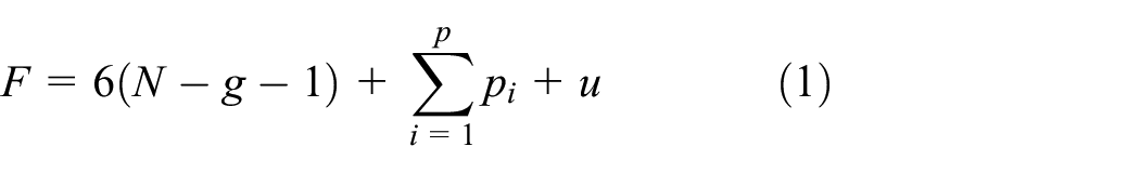
Where g is the total number of kinematic pairs, p i represent the degree of freedom of the i-th pairs, u is the number of over-constraints in mechanism.
Considering that the joints of underground heavy-load robot are mainly for transmitting force and bearing loads. Therefore, the mechanism should adopt low kinematic pairs.

Where p l is the number of low kinematic pair, n is the number of movable components in mechanism (n = N−1).
According to equation (2), in order to make the number of low kinematic pairs p l to be an integer, n and F must be even or odd simultaneously. The numbers of basic loops L in kinematic chain of mechanism should meet 21 :

Where L represents the number of basic loops in mechanism.
Considering the structural design requirements, the structure of underground heavy-load robot should not be too complex, and the number of driving sources should be limited as much as possible. So, the number of basic loops in configuration should be less than the number of F, that is
Configuration scheme of underground heavy-load robot.

Because the component i in the closed kinematic chain is connected with at least i−2 components, the relationship between i and n is:

Where i is the number of kinematic pairs.
That is
At the same time, the total number of low pairs p l and n in the mechanism satisfy:

Where n i represent the number of i-level kinematic pairs in the mechanism chain.
The total number of components N in the kinematic chain of mechanisms is:

According to the topological relation of structure,
22
Feasible configuration schemes of underground heavy-load robot.
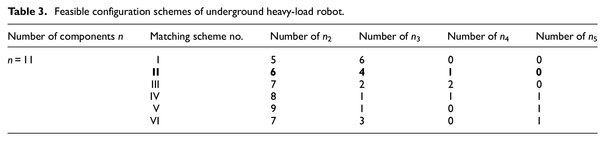
Not all these six types of configuration schemes listed in Table 3 meet the design requirements of underground heavy-load robot. To get the optimal configuration, further matching will be carried out in accordance with the design requirements and constraints. 23 The six configuration schemes in Table 3 will be optimized and matched from three aspects: the existing forms of component configuration, driven part configuration and overall topology structure configuration.
The existing forms of component configuration
To meet the requirements of flexible operation in the underground confined working space, the moment of inertia for each movable component should be reduced as much as possible, so the complex structure forms should be avoided. Therefore, the multi-rod pairs should be avoided, and the n4 and n5 cannot exist simultaneously. So, the configuration type IV should be excluded.
The basic structural points of fuselage of underground heavy-load robot must be adjacent to the frame and provide auxiliary rotation, lifting and translation movement. This implies that there must be at least one four-rod pair n4. Therefore, scheme I, V and VI should be excluded.
Topological conditions of driven parts
To ensure the reliable and stable execution of various heavy-load operations, the executive-arm should contain at least two hydraulic driven loops. Specifically, the hydraulic driven loops of executive-arm contain two pair n2. At the same time, in addition to connecting the hydraulic driven loop, it also needs to relate to the other parts of executive-arm. So, the executive-arm should have at least two n3 pairs, and the active part used to connect executive-arm and fuselage should have at least one n3 pair, then the total number of n3 pair in mechanism should satisfy n3 ≥ 3. Thus, the scheme III can be excluded. The scheme II can be determined as the optimal feasible configuration scheme for underground heavy-load robot.
The topology structure should be the simplest
There are 212 kinds of topological configuration schemes for planar 12-Bar 5-DOF mechanism (The scheme II: N = 12, n = 11, F = 5, n2 = 7, n3 = 4, n4 = 1). 24 According to the principle of “shortest motion transfer loop,” the 212 kinds of topological configurations should be matched. 25 The optimal configuration of underground heavy-load robot can be obtained as shown in Figure 2.
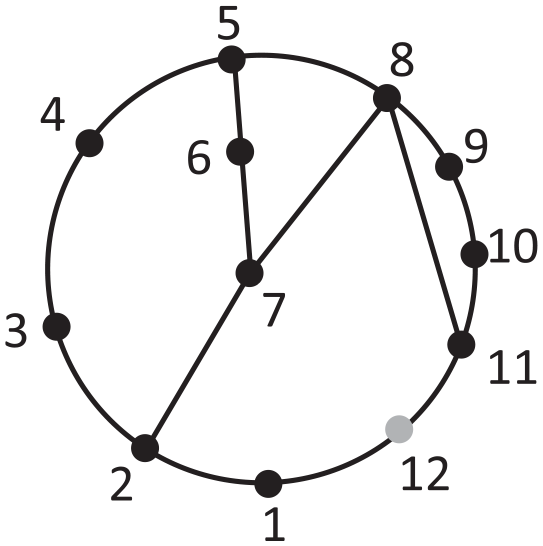
Structural topology configuration diagram of underground heavy-load robot.
Finalization of configuration scheme
In according with the structural topology configuration diagram of underground heavy-load robot, assuming that 11 is the end output actuator, according to the motion transmission relationship and sequential connection form, 7, 8 and 12 are the executive big-arm, small-arm and frame of robot in turn. Specifically, 3 and 4 are the driven hydraulic cylinder for big-arm, 9 and 10 are the driven hydraulic cylinder for small-arm, 1 is the fuselage and 2 is the connection turntable between executive-arm and fuselage. The structural diagram is drawn as shown in Figure 3.
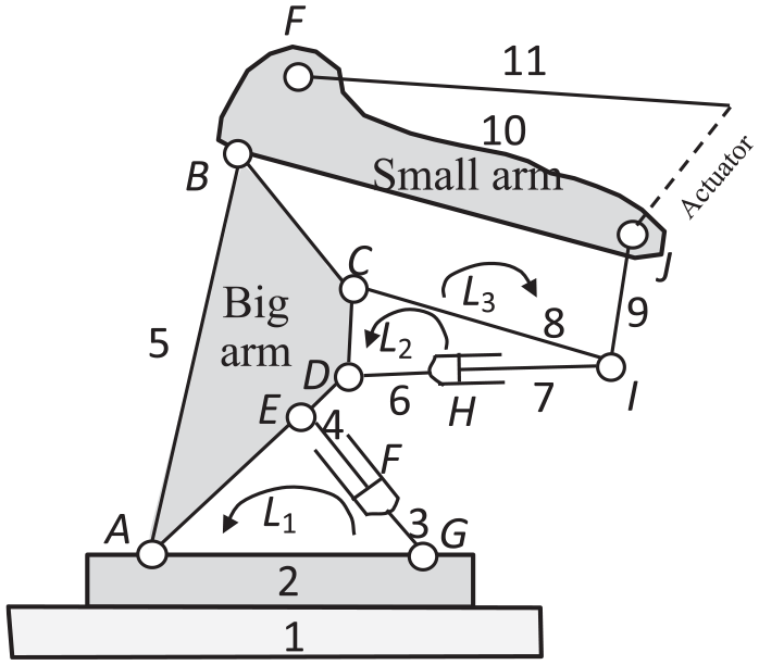
Structural diagram of underground heavy-load robot.
In Figure 3, A, B … K are the kinematic pairs, L i represent the basic loops in the mechanism (i = 1, 2, 3).
As shown in Figure 3, the finalized configuration scheme of underground heavy-load robot adopts hybrid configuration, in which the executive-arm is a multi-loop coupling mechanism with three independent loops. The underground heavy-load robot has the following innovations.
① The underground heavy-load robot is composed of three four-bar loops (L1, L2 and L3). This hybrid configuration can effectively alleviate the weakness of series configuration.
② Through reasonably matching the shortest transmission route of big-arm driven loop L1, the precise control of big-arm, small-arm and end actuator can be realized, thus achieving the reliable and accurate output of the whole system.
③ The parallelogram structure loop L2 between big-arm and small-arm can effectively improve the force state of executive-arm and reduce the impact of heavy-load on the executive-arm. Therefore, the carrying capacity and output posture of robot can be improved.
④ The executive-arm and end actuator are connected through loop L3, which is benefit to increasing the flexibility of output actuator.
Implementation of scale synthesis based on modularization
Based on the known configuration of the mechanism, scale synthesis can be realized through the design of geometric structure parameters, to obtain better adaptability and coordination ability of the whole mechanism. According to module division principle, the optimal scale synthesis and implementation of underground heavy-load robot will be realized from the main motion module, auxiliary motion module and expansion module. The implementation scheme is shown in Figure 4.
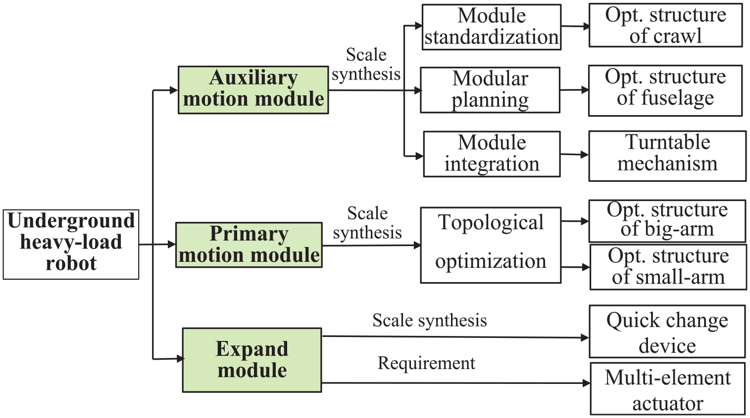
Modular design diagram of underground heavy-load robot.
Then, the reasonable comprehensive scale optimization of each module for underground heavy-load will be studied respectively.
Scale synthesis of primary motion module
By coordinating the executive-arm (including big-arm, small-arm) and the corresponding hydraulic control loop, 26 the primary motion module of underground heavy-load robot can flexibly and stably complete various heavy-load operations in the confined space.
During the actual operation, the executive-arm bears complex spatial dynamic variable loads. The generated dynamic load will act on fuselage and make the fuselage bear additional torque. At the same time, affected by the actual working conditions and mutual coupling relationship among various modules, the optimization synthesis of executive-arm becomes a typical complex nonlinear optimization issue. It is difficult for conventional methods to find the optimal solution in a short time. Considering that the structural topology optimization research is limited to the structural optimization of single part in ideal condition,
27
the obtained structural scale is difficult to satisfy the needs of actual conditions. Therefore, the topology optimization model for scale synthesis of executive-arm is established, which takes the geometric structure (s
i
and l
i
) as design variables, and the working conditions as design constraints G
i
(Ldi,V,
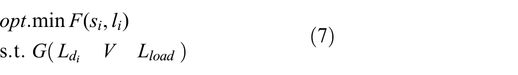
Where F(s
i
, l
i
) is the objective function of comprehensive scale optimization of executive-arm, s
i
represent the size scale of executive-arms and l
i
represent the shape scale of executive-arm. G
i
(X) represent the design constraints. L
di
represent the length constraint of executive-arm (L
d
1∈[0, 470], L
d
2∈[0, 540], L
d
3∈[0, 470]). V represent the spatial volume constraint (the total width of executive-arm is not exceed 1100 mm and the total height is not exceed 1200 mm) and
Constraint model:

Where
Scale synthesis for the executive-arm
The geometric structural scale for executive-arm mainly includes the determination of geometric structure scale (s i and l i ) for big-arm and small-arm. Based on the comparison of typical executive big-arms and practice and experimental statistics, 28 because the stress on front, middle and rear sections of executive-arm is different, the shape dimension l i of executive-arm are suitable for adopting different widths (the front and rear sections of executive-arm adopt different bending angles), and the dimension s i of front, middle transition and rear sections of executive-arm should also be optimized accordingly, so as to alleviate the large transfer stress on middle bending section and improve the overall stiffness of executive-arm. The geometric structural scale (s i and l i ) of executive big-arm and small-arm of underground heavy-load robot are optimized, and the results are shown in Figure 5.

Structural scale optimization of executive-arm for underground heavy-load robot: (a) geometric structure scale of executive big-arm and (b) geometric structure scale of executive small-arm.
Topology optimization of executive-arm scale
After the designing of geometric structure scale for executive-arms, to satisfy the design constraints G
i
(Ldi,V,

Topology optimization of executive-arm: (a) topology optimization of big-arm and (b) topology optimization of small-arm.
During the operation, both the big-arm and small-arm are in a stretched state. As shown in Figure 6(a): After topology optimization, the maximum stress of big-arm is reduced to 23.86 MPa, and the effective mass is reduced by 33%. As shown in Figure 6(b), dimensional topology optimizations for these connecting holes (size and position) are carried out. After optimization, the maximum stress value of small-arm reduced to 33.41 MPa, and the effective mass is reduced by 18.81%.
By topology optimization, the strength and rigidity of whole executive-arm are effectively improved, and the main motion module with reasonable structure, perfect heavy-load performance, small self-weight ratio and high spatial utilization are realized.
Scale synthesis of auxiliary motion module
The auxiliary motion module provides the auxiliary degrees of freedom for the robot. The dual crawler assist the robot to complete the non-fixed point transportation/transfer heavy-load operations, the fuselage accommodates all the driving, control, electrical and other devices, and the turntable assists executive-arm to realize lifting and rotating movements. The scale synthesis of these three auxiliary parts are studied respectively as follows.
Standardization of crawler
The underground heavy-load robot is used to carry heavy objects, the traveling speed should not be too high. So, the walking module uses dual crawler configuration to adapt the non-structural walking conditions. The crawler walking module is mainly composed of chassis frame, crawler assembly and driving wheel, etc. 29 Parametric design is carried out for crawler walking module to form standard series products, as shown in Figure 7.
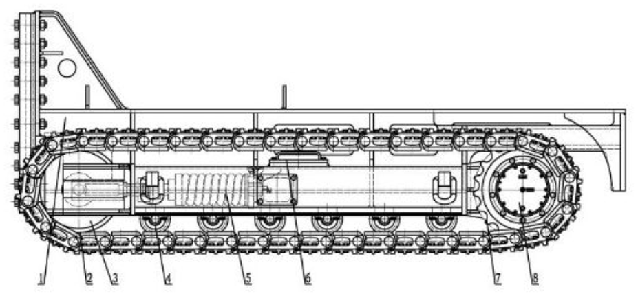
Dual crawler walking module.
According to the required power of robot, the series of crawler motion modules are matched to form a complete set of crawler walking module equipment, which can be popularized and applied to crawler walking mechanisms such as bulldozers, excavators, tanks, mining transporters and loader machine.
Parametric design and implementation of fuselage
The fuselage is mainly used to accommodate control pump station, hydraulic oil tank, electric control box, radiator, etc. The preliminary fuselage structure of underground heavy-load robot is shown in Figure 8(a).
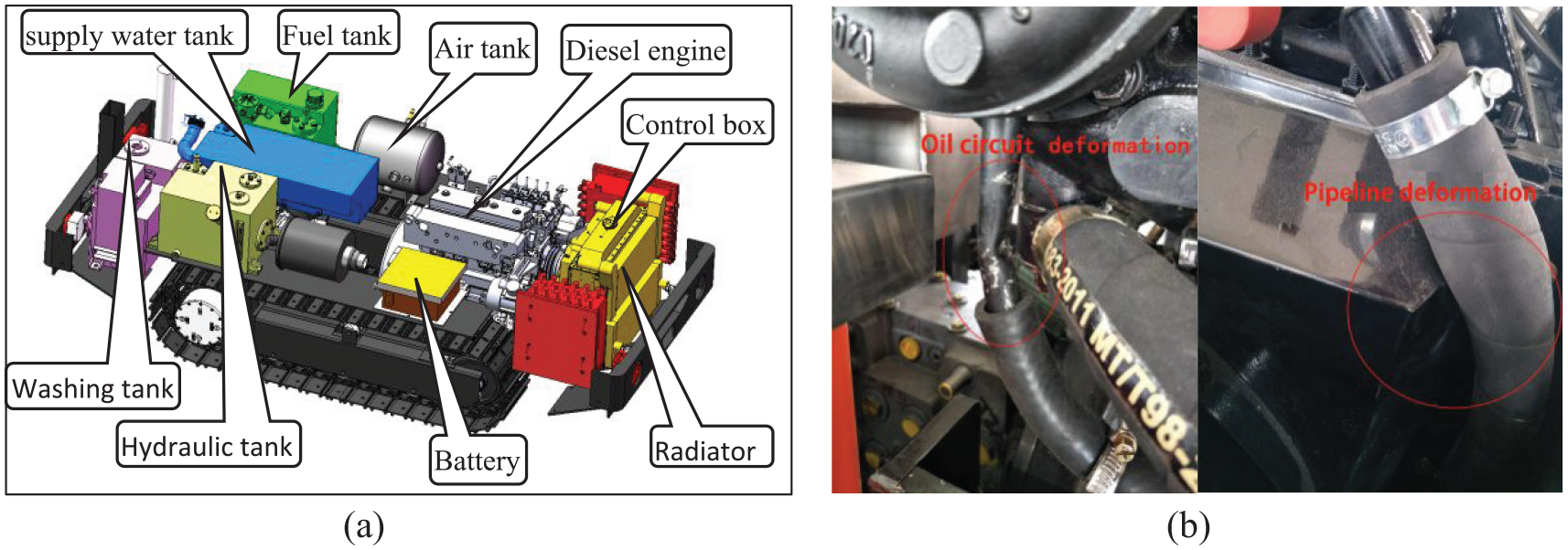
Layout of crawler fuselage module and assemble problems: (a) layout of fuselage and (b) practical assemble problems of fuselage.
The overall structural scheme of fuselage is compact, but due to the lack of reasonable overall arrangement of electrical and hydraulic control systems, there were some assembly problems such as excessive bending deformation of pipeline and interference of parts, as shown in Figure 8(b). Moreover, due to the too tight arrangement of internal devices, it is quite difficult to deal with the repair and maintain work. Therefore, the scale of fuselage is optimized.

Where V(m i ) is the objective function of fuselage module, and m i represent the weight of main components in fuselage module (such like hydraulic tank, diesel engine, fuel tank et al, i = 1, 2, 3 … 7). W(m i ) is the width constraint function, L(m i ) is the length constraint function, restricted by the working space in the tunnel, Wmax ≤ 1200 mm and Lmax ≤ 1350 mm are the maximum width and length of fuselage respectively.
According to the optimization model, the following optimization adjustments are made by reasonably matching and coordinating the equipment (pumps, electronic control parts, pipelines, etc.) in the fuselage, and the quality balance and heat balance of whole fuselage system are also considered.
① Considering the closed underground working environment, the capability and endurance capability of hydraulic tank is matched, to match the tank capacity of underground heavy-load robot.
② The water tank is mainly used to cool the diesel engine. The scale of water tank should be adjusted according to the heat balance demand, and it is recommended to install the water tank as close as possible to diesel engine and heat dissipation device, to improve the cooling effect and shorten the stroke of cooling pipeline.
③ The operation of the robot is achieved by controlling each hydraulic-driven loop, so the position of control box should be adjacent to hydraulic system, to reduce unnecessary hydraulic transmission pipeline and improve the control effect.
The final layout of fuselage after comprehensive optimization is shown in Figure 9.

Modular optimization of fuselage.
Through the comprehensive optimal layout of fuselage, the hydraulic oil tank and water tank are reasonably matched according to the required dynamic parameters, and the utilization rate of hydraulic control loop and cooling pipeline in fuselage can be effectively improved. It is more convenient for installation, maintenance and repair. Moreover, the scale parametric design of each device in fuselage is adjusted according to the design target V(m i ), which matches with the series design of crawler walking module and main motion module and improves the design efficiency of whole robot.
Design and development of integrated lifting-transfer-rotate turntable
The executive big-arm and small-arm of underground heavy-load robot adopts a series connection configuration to meet the requirement of flexibly rotate 360° in confined working space. To relieve the pressure of heavy-load to executive-arm, the integrated lifting-transfer-rotate turntable is designed, as shown in Figure 10.

The model of integrated turntable.
The turntable mainly consists of the following components: The lifting mechanism is connected to the fuselage of underground heavy-load robot. It can enable the entire executive-arm to lift along the vertical direction by ±220 mm. The translating mechanism can control the executive-arm to translate along horizontal direction by ±200 mm. The rotary mechanism is connected to the executive-arm and can enable the executive-arm to rotate freely by ±180°. The integrated turntable can effectively enhance the strength of the executive-arm and expand the effective working space and applicability of the underground heavy-load robot.
Development of expansion module
The complex working environment requires robots to have the ability to complete various tasks. Although reconfiguration and multi-arm robots have become the trend, they cannot meet the market demand of variable changeable output operations. Therefore, this paper proposes an expansion module for heavy-load robot: the end of executive-arm is connected to various output actuators via a fast-change-device with standardized interface, to realize different types of output. The output actuator for lifting, griping and supporting are shown in Figure 11.

Developed output actuators.
The extensive module proposed in this paper can realize various forms of heavy-load output without changing the configuration of robot, and expand the application scope of underground heavy-load robot.
Overall assembly of underground heavy-load robot
After the configuration design and scale synthesis of underground heavy-load robot, the virtual assembly prototype of underground heavy-load robot is shown in Figure 12.

Virtual assembly prototype of underground heavy-load robot.
The developed underground heavy-load robot has the following innovative features.
(1) The underground heavy-load robot is composed by three hydraulic driven loops, which can effectively alleviate the weakness caused by series structural configuration, to improve the bearing capacity, stability and overall robustness of robot. What is more, in the non-working state, the executive-arm can be folded and kept flush with fuselage to reduce spatial occupation.
(2) In accordance with the actual external loads, the scale of three modules are coordinated and reasonably assembled, to simplify the design and manufacturing process, and enhance the flexibility and scalability of underground heavy-load robot.
Aiming at the problem that most design and development research mainly focuses on the structural design of robots, and there is a lack of coordination between the overall structural design and scale synthesis, which makes the developed robots unable to meet the actual production needs of performing multiple operations under complex working conditions. Based on the requirements of special underground working conditions and heavy-load operations, this paper designs an underground heavy-load robot with strong adaptability, high flexibility and stability by combining structural configuration development and scale realization. This method can effectively shorten the design cycle and enhance the flexibility and adaptability of the heavy-load robot.
Performance evaluation of underground heavy-load robot
Due to different design requirements, the performance evaluation indexes of robot systems are different, such as minimum freedom degree, dexterity and fusion of multiple performance. 29 Based on the kinematic and dynamic model, this paper establishes system performance evaluation index P(x), to evaluate the operation performance of underground heavy-load robot.
Analysis model for underground heavy-load robot
Kinematic model
Kinematics and dynamics models are the basis for analyzing the performance of robots. The D-H model of underground heavy-load robot is constructed as shown in Figure 13.

D-H model of underground heavy-load robot.
The parameters of D-H motion analysis model are shown in Table 4.
Parameters table of D-H model.

Dynamic analysis model
The mechanical body of underground heavy-load robot is a typical complex multi-mechanical body, besides, because of the unknown nonstructural environment and heavy-load operation conditions, its dynamic analysis becomes complex. So, assuming:
(1)Each component of underground heavy-load robot is a rigid body without elastic deformation.
(2)The stiffness of crawler is K m 1 and the damping is K c 1. The stiffness of turntable and executive-arm are K m 2 and K m 3, the damping is K c 2 and K c 3 respectively.
(3)The connection between each part is elastic.
The dynamic model of underground heavy-load robot is shown in Figure 14.

Dynamic analysis model of underground heavy-load robot.
In the Figure 14, M i represent the quality of each module, ∑F represent the total bearing loads.
The Lagrange Equation 15 of dynamic system for underground heavy-load robot is:

Where t is the operation time of robot system, q
i
represent the generalized coordinate and Q
i
represent generalized force of system (
According to the kinematic model of underground heavy-load robot, the dynamic analysis model is constructed in MATLAB Simulink, then the system output response under no-load and heavy-load conditions (carrying 2 T) are simulated as shown in Figure 15.

Simulation results of underground heavy-load robot system in Simulink.
As shown in Figure 15, under no-load condition, the executive-end, turntable and fuselage of underground heavy-load robot generate transient step-response after inputting a step signal. At t = 3.205 s, the maximum transient response generated by the executive-end is 12.72 mm, and after t = 4.305 s, the executive-end gradually approaches equilibrium. At t = 3.1915 s, the maximum transient response generated by the turntable is 11.27 mm. And after t = 4.151 s, the turntable gradually approaches equilibrium. At t = 3.198 s, the maximum transient response generated by the fuselage is 6.608 mm, and after t = 4.093 s, the fuselage gradually approaches equilibrium.
By contrast, under heavy-load conditions, the executive-end, turntable and fuselage of underground heavy-load robot also generate transient step-output after imputing step signal. At t = 3.2935 s, the maximum transient response generated by executive-end is 14.93 mm, and after t = 5.541 s, the executive-end gradually approaches equilibrium. At t = 3.2915 s, the maximum transient response generated by turntable is 11.27 mm. And after t = 5.281 s, the turntable gradually approaches equilibrium. At t = 3.302 s, the maximum transient response generated by fuselage is 7.585 mm, and after t = 5.035 s, the fuselage gradually approaches equilibrium.
According to the simulation results, whether under no-load condition or heavy-load condition, the underground heavy-load robot can work normally and smoothly.
Performance evaluation system of underground heavy-load robot
At present, scholars use different methods and indexes to evaluate the performance of robots, such as reachable position in working space, velocity characteristics, and dexterity cloud image etc. 30 For the special tunnel working conditions, the heavy-load robot adopts a hybrid driving mode that combines electric drive and hydraulic drive. However, the existing methods and indexes for evaluating robot system performance are not comprehensive. Therefore, the system performance evaluation set P(x) is constructed in this paper.

Where P(x) is the system performance evaluation set of robot, P S is the index of effective workspace, P D is the index of dexterity and P E is the index of energy loss.
Comparing with the performance evaluation index proposed in other references, the performance evaluation system P(x) is more reasonable and comprehensive.
Effective working space index P W
The working space of robot refers to the spatial points that the center of executive-end can reach. Thus, it can be used to evaluate the motion range of robot.
Reachable working space V re
The working space of underground heavy-load robot is underground roadway, tunnel or chamber with trapezoidal, rectangular or semi-circular arch section, and is accompanied by various dynamic/static obstacles. In this paper, the semi-circular arch roadway is taken as an example to analyze the working space of underground heavy-load robot, as shown in Figure 16.

Working space model of underground heavy-load robot.
The reachable working space is the area that can be reached by the maximum joint motion angle without interference. The reachable working space is related to the configuration of robot. The reachable working space of underground heavy-load robot can be regarded as the vector synthesis of its three modules.

Where V i respectively represents the reachable working space of crawler motion module, turntable motion module and executive-arm (i = 1, 2, 3).
The actual effective reachable working space

Where L1 represents the reachable working space of crawler motion module, v represents the velocity of fuselage, L2 is the effective working arm length of integrated turntable, θ2 is the rotation angle of integrated turntable. L3 i represent the effective working arm length of executive-arm, θ3i represent the rotation angle of executive-arm.
Effective working space index P W
The flexibly movement ability of robot in reachable working space directly affects the efficiency of completing specific tasks. Therefore, the per unit length reachable working space criterion P W is introduced.

Where
On the premise of same working depth, the maximum effective reachable workspace

Where
The higher effective working space index E W , the better accessibility and higher availability of effective working space of robot.
To conduct the qualitative analysis of effective reachable workspace index P W of underground heavy-load robot, the reachable working space can be decomposed into the horizontal plane and the vertical plane.
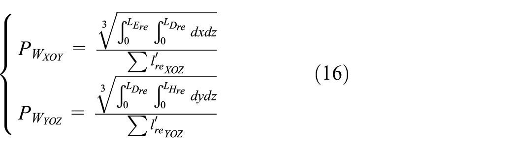
Where L Ere , L Hre and L Dre are the effective width, height and depth of underground heavy-load robot in reachable working space respectively.
Dexterity index P D
When designing and developing a robot, it is required that the robot can flexibly complete various tasks in the working space. This paper combines motion parameters and reachable working space function to evaluate the motion dexterity P D of underground heavy-load robot.
According to the forward motion solution of spatial mechanism, the actual output spatial posture W out of robot can be expressed.
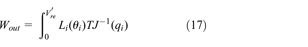
Where u i represent the unit joint vector b i to vector ai.
J(q i ) represent the Jacobian maxi of joint q i .

The dexterity index E D of robot can be viewed as the ability of efficiently reaching the desired spatial poison with optimal posture state.
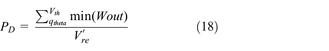
Where qtheta is the motion angle of each joint
Obviously, the dexterity index P D of robot is related to motion parameters and reachable working space. The higher dexterity index P D , the higher effective utilization of working space.
System energy consumption index P E
Affected by underground explosion-proof requirements, power supply and other factors, the underground heavy-load robot mainly uses the hydraulic cylinder to provide the driving force and overcome its own weight, energy loss and external loads. If the loads to be overcome are too large, it will not only increase energy consumption, but also reduce its output dexterity, smoothness and accuracy of underground heavy-load robot. Therefore, the actual energy consumption system can be regarded as one of the performance indexes for evaluating the preference of robot.
The energy consumption of robot system refers to the total energy consumed while completing certain task, which includes system loss energy and system driven energy two parts, then the system energy consumption index P E can be obtained:

Where E J is the mechanical energy loss of robot system, and E d is the hydraulic driven energy of robot system.
The mechanical energy loss of robot system E J caused by overcoming the external loads, gravity of robot itself and friction of hydraulic loops.

Where T is the total required time to complete single task, n is the number of joints, θ
i
represent the motion angle of each joint,
The hydraulic driven energy of robot system E D is:
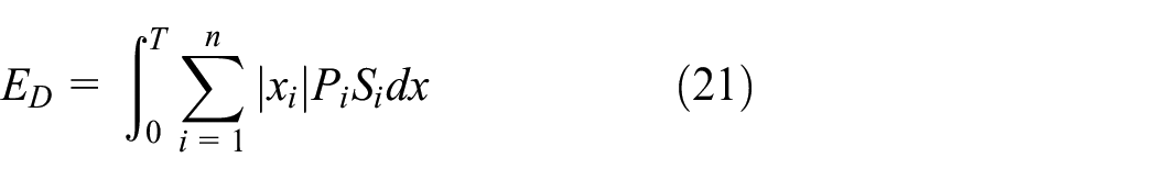
Where P i represent the pressure of driven hydraulic cylinders, S i represent the sectional area of hydraulic cylinders.
The higher energy consumption index P E , the higher bearing capacity and working efficiency of robot.
In accordance with the performance evaluation system P(x), the reasonable and comprehensive performance evaluation of underground heavy-load robot can be realized.
Experiment and simulation
Experimental equipment
The heavy-load robots with equivalent hydraulic driven sources (35 kW) are chosen for performance test under the same working condition. The parameters of heavy-load robots are shown in Figure 17.

Testing heavy-load robots: (a) transport heavy-load robot and (b) underground heavy-load robot.
Performance testing
As the key component of heavy-load robots, the performance of executive-arm directly affects the working performance of whole robots. In this paper, under the condition of lifting and transferring a 2 T heavy-load 2 m away from fuselage, the transient performance of executive-arm for transport heavy-load robot and underground heavy-load robot are simulated as shown in Figure 18.

Simulation analysis of executive big-arm for transport heavy-load robot: (a) stress simulation of executive-arm and (b) strain simulation of executive-arm.
As shown in Figure 18(a). The maximum stress of executive-arm is 41.72 MPa, which appears between the hinge of executive-arm and turntable. As shown in Figure 18(b), the maximum deformation of executive-arm is 6.232 mm, which is located at the forearm of small-arm.
The simulation results of executive-arm for underground heavy-load robot are shown in Figure 19.

Simulation analysis of executive-arm for underground heavy-load robot: (a) stress simulation of executive-arm and (b) strain simulation of executive-arm.
The maximum transient stress of executive-arm for heavy-load robot is reduced to 8.599 MPa as shown in Figure 19(a). And the maximum deformation of executive-arm is reduced to 1.5786 mm as shown in Figure 19(b).
According to the above simulation results, we can see that when bearing the same heavy-load, the stress and strain of underground heavy-load robot are lower than those of the transport heavy-load robot, which means that the stiffness and stability of underground heavy-load robot are superior than those of transport heavy-load robot.
Based on the simulation results, the stress and strain of transport heavy-load robot and underground heavy-load robot are measured respectively. 26 Subsequently, the test results and simulation results are collated and contrasted, as presented in Table 5.
Comparison between simulation results and test results.

Comparing the statistical data in Table 5, the deviation accuracy between established virtual prototype model and actual prototype is less than 10%, which shows the reliability and accuracy of the virtual prototype model, so the prototype simulation model can be used for subsequent related performance testing research.
Performance comparison and analysis
Comparative analysis of effective working space
Based on the actual configuration scale of three heavy-load robots, the ROBOTIC models for heavy-load robots are constructed in MATLAB, to analyze and compare effective reachable workspaces of the three heavy-load robots when implementing fixed-point operation mode, as shown in Figure 20.

Effective workspace of heavy-load robot: (a) effective workspace analysis of transport heavy-load robot, (b) effective workspace analysis of industry heavy-load robot, and (c) effective workspace analysis of underground heavy-load robot.
According to the effective workspace of heavy-load robots in XOY plane and YOZ plane analyzed in Figure 20, the geometric parameters of heavy-load robots are substituted into equation (16), and then the reachable working space index P W can be calculated, as shown in Table 6.
Statistics of reachable workspace index E W .

According to Table 6, because the transport heavy-load robot lacks the freedom degree of pitching, both the reachable working space index P W in XOY plane and YOZ plane are the lowest among the three heavy-load robots. Although the reachable working space index P W of industrial heavy-load robot is similar to that of underground heavy-load robot, the industrial heavy-load robot lacks the moving ability and cannot complete the non-fixed heavy–load works. Therefore, the underground heavy-load robot designed in this research can comprehensively satisfy the requirements of flexible operations under the restricted underground working conditions.
Comparative analysis of dexterity index
The smoothness of a robot’s spatial motion trajectory directly reflects the dexterity and stability of the robot. The spatial operation trajectory of single lifting and transferring heavy-load are shown in Figure 21.

The spatial trajectory for heavy-load robot: (a) spatial trajectory of transport heavy-load robot and (b) spatial trajectory of underground heavy-load robot.
As shown in Figure 21, the trajectory of the heavy-load robot is significantly smoother than that of the transport heavy-load robot, especially at the connection points of the trajectory.
Test of system energy consumption index PE
According to the constructed system performance evaluation set P(x), the system energy consumption index
Comparison of energy consumption index of heavy-load operation.
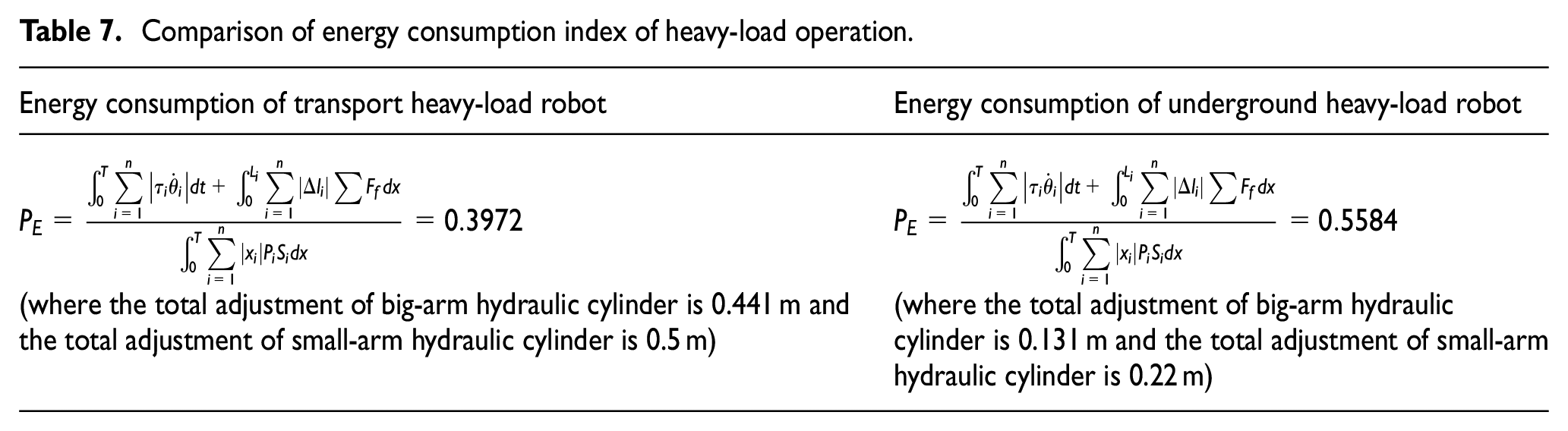
As shown in Table 7, the energy consumption index P E of underground heavy-load is higher than that of transport heavy-load robot, which means that underground heavy-load robot has superior bearing capacity and working efficiency.
Conclusion
Oriented to the requirements of special underground working conditions and heavy-load operations, this paper deduced the new configuration scheme of the underground heavy-load robot with strong adaptability, high flexibility and stability by combining structural configuration development and scale realization. This scheme can reduce the complexity of control system and simplify the design and manufacturing cycle of robot. Moreover, this paper constructed the system performance evaluation index for underground heavy-load robot to realize the reasonable performance evaluation of robot system. The experimental and situational results verified that the underground heavy-load robot is not only reasonable in structure, but also has a greater bearing capacity and more comprehensive functions, and can fully meet the requirements of high-risk and complex working conditions in coal mines. The research in this paper provides new ideas for the structural development of heavy-load robot, effectively enhances the design efficiency of spatial multi-freedom degree industrial robot, and lays a foundation for the coordinated control of modern intelligent robots.
The work of this paper provides new ideas for the structural development of heavy-load robots, effectively improves the design efficiency of spatial multi-freedom degree industrial robots, and lays a foundation for the coordinated control of modern intelligent robots. Furthermore, the works of this paper also provide strong support for realizing intelligent mining. However, the performance testing analysis in this paper mostly adopts simulation analysis and surface testing, which has a certain deviation from the actual underground conditions, thereby affecting the robustness of the underground heavy-load robot. Next, to enhance the robustness of the underground heavy-load robot, this project will focus on developing an efficient control system for the underground heavy-load robot.
Footnotes
Handling Editor: Sharmili Pandian
Funding
The author(s) disclosed receipt of the following financial support for the research, authorship, and/or publication of this article: This work is supported by the Ningxia Natural Science Foundation Project (2024AAC03184), Youth Talent Cultivation Project of North Minzu University (2024QKPY03&2024QNPY15) and Ningxia Scientific and Technological Innovation Team (2024CXTD001).
Declaration of conflicting interests
The author(s) declared no potential conflicts of interest with respect to the research, authorship, and/or publication of this article.
Data availability statement
All code generated or used during the study are available from the corresponding author by request.