
Abstract
Analyzing the different characteristics of tangent lines of the coupler point curve of 4R mechanism, a 3R kinematic chain in a singular configuration is set up, planar and spherical 7R mechanisms with motion and locking modes are synthesized. Based on the spherical 4R mechanism with threefold and quadruple points on the coupler point curve, a spherical 7R mechanism with multiple motion and locking mode is ã synthesized. By analyzing the spherical 7R mechanism using screw theory, the motion mode transformation configuration of the mechanism when the coupler point curve of the spherical 4R loop is at a cusp are analyzed. The results show that this type of 7R mechanism can achieve the transformation of motion and locking modes. By changing the configuration of the singular 3R kinematic chain, the motion mode of the 4R mechanism loop under different motion bifurcation configurations can be transformed. The proposed method also has certain application value in designing, analyzing, and optimizing multi-mode mechanisms that meet the transformation requirements of motion and locking production operations.
Introduction
Multi-mode mechanisms 1 can adapt to different work requirements through mode transformation without reassembly. During the transformation of motion modes, some multi-mode mechanisms have their links and kinematic pairs in a locking state. In some applications, by transforming the motion mode to a locking state, the rigidity of the mechanism can be improved. For example, in legged landers, the leg structure needs to have both folding and walking motion modes. During landing, the leg structure is in a locking state, thus providing the ability to bear high loads and resist strong impacts. 2 When some robots with mobile bases are working under load, the mobile base has a locking mode that can maintain the stability of the robot’s body posture during operation. 3
When the motion mode of a multi-mode mechanism changes or the number of degrees of freedom is altered, the components and kinematic pairs of the mechanism may transition from a motion state to a locking state. Lin et al. 4 proposes a method based on the geometric characteristics of elliptical bifocal points, synthesis a spatial single-loop mechanism with the axis of the rotational pair passing through the geometric intersection of ellipses, to analyze the joint locking characteristics under different motion modes and apply it to the main frame of a wall-climbing robot. Li et al. 5 designs a material with negative Poisson’s ratio characteristics and high folding ratio characteristics. The material structure consists of a single-loop 6R mechanism module with multi-mode characteristics. When the multi-mode 6R mechanism undergoes mode transformation, some joints are in a locking state. Nie et al. 6 inserts two intersecting rotational pairs into a parallelogram mechanism to obtain a spatial 6R mechanism with six motion modes. Using screw theory analysis and Denavit–Hartenberg parameter kinematic modeling, it is analyzed to have one 2-joint locking mode and three 4-joint locking modes, which are applied to a variable structure wheeled frame. Zhang et al. 7 increases the working space of the mechanism through mode transformation and applies it to human rehabilitation equipment. Zhang et al. 8 uses the spatial 6R mechanism as a generalized variable motion joint, locks its motion pairs, and achieves the transformation of multiple motion modes, establishing a unified kinematic model for multiple motion modes. Kang et al. 9 adds four rotational pairs to the Bennett mechanism to obtain an 8R mechanism. Using screw theory analysis, different motion modes of the spatial 7R mechanism are obtained by locking different joints of the 8R mechanism. This method provides a new research perspective for the synthesis of new metamorphic mechanisms. Zhang et al. 10 uses an equivalent kinematic chain to simulate the crease motion of traditional folding mechanisms and designs a rigid-flexible coupled folding robot. By using flexible materials, it avoids the motion uncertainty issues of traditional rigid robots, and by using rigid kinematic chains, it solves the problems of low load capacity and low accuracy of traditional flexible folding robots. Yang et al. 11 uses an 8R mechanism as the torso of a walking robot. Through the transformation of the motion mode of the 8R mechanism, some motion pairs are locked to enhance the passing performance of the walking robot in different environments. Zhao et al. 12 uses a 3RRU-type parallel mechanism as a unit module of a grasping manipulator. When the manipulator transform between deployment and grasping modes, the parallel mechanism’s moving platform is in a locking mode. In the Rosyid et al., 13 a 3T parallel machining robot featuring both non-isotropy and isotropy modes was designed by utilizing a reconfigurable frame and lockable joints. This design expanded the robot’s machining workspace and the types of workpieces that can be processed. In the Tang and Dai, 14 a spatial 6R mechanism, consisting of two spherical 3R kinematic chains connected in series, was proposed. When its two joints are locked, the mechanism operates in either a spherical 4R or Bennett mechanism motion mode. Based on the analysis of this metamorphic mechanism’s motion modes, a novel method for designing multi-mode mechanisms was introduced.
The design and analysis of multi-mode mechanisms with locking modes remains a complex problem. The existing design methods include: (1) merging two overconstrained mechanisms to construct a single-loop multi-mode mechanism. (2) adding a kinematic pair to an overconstrained mechanism to design a multi-mode single-loop mechanism. (3) using high-order kinematic equations 15 to design a single-loop mechanism with concealed motion bifurcation characteristics. (4) by merging a multi-mode multi-loop mechanism with a serial kinematic chain, 16 a parallel mechanism with motion modes of different dimensions is designed. Based on the analysis of tangents of planar 4R and spherical 4R link trajectories, this paper proposes a method for synthesizing mechanisms with both motion and locking modes by setting up a folded 3R kinematic chain. When such mechanisms move to a specific working pose, they can further enhance their load capacity and stiffness by switching to a locking state through motion mode transformation, adapting to different operational requirements.
A planar 7R mechanism with motion and locking modes
As shown in Figure 1(a), the link 2 of the parallelogram mechanism can rotate around the axis R1. When the mechanism moves to the configuration shown in Figure 1(b), it is in a constrained singular configuration, and the axes of the rotational pairs R1, R2, R3, and R4 are in a coplanar configuration. At this time, the axes of the rotational pairs R2 and R4 coincide, and the kinematic chain R4R3R2 can rotate as a whole around the axis R4 when the link 2 is in a locking mode, as shown in Figure 1(c). When the link 2 is in a rotational motion mode, the speed v1 on the link 2 and v2 on the coupler 3 of the coincident point A should have the same direction of movement, as shown in Figure 1(a) and (b). When the axes of joints R2 and R4 coincide and links 3 and 4 rotate about R4 as a whole which the link 2 remains stationary, the velocity of point A is zero and does not have any direction. At this time, only the speed direction of point A as v1 on the link 2 and v2 on the coupler 3 are permitted. When the permitted directions of v1 and v2 are different, the movement speed of point A should be zero, and the link 2 is in a locking mode and cannot change its motion mode, as shown in Figure 1(c). As shown in Figure 1(b), when the coupler 3 rotates around the axis of the rotational pair R4 and reaches the mechanism configuration shown in Figure 1(c), the directions of v1 and v2 are different, and the link 2 is in a locking mode. As shown in Figure 1(b), when the link 2 rotates around the axis of the rotational pair R1 and reaches the mechanism configuration shown in Figure 1(a). The mechanism configuration shown in Figure 1(a) is not a constrained singular configuration. The directions of v1 and v2 are the same, and the link 2 is in a motion mode.

Parallelogram mechanism with both locking and motion modes: (a) unlocking mode, (b) motion mode transform configurations, and (c) locking mode.
Assembly conditions with motion and locking modes
The curve of point B1 on link 2 of kinematic chain R1 shown in Figure 2(a) is a circle centered at R1. In kinematic chain R4R3R2, the lengths of link 4 and coupler 3 are the same, that is, l4 = l3, so the workspace of point B2 on coupler 3 is a circle centered at the rotation center of R4 with a radius of 2l3. When there is an intersection between the workspace of point B1 on kinematic chain R1 and the workspace of point B2 on kinematic chain R4R3R2 as shown in Figure 2(b), the planar 4R mechanism can be assembled, as shown in Figure 2(b). At this time, the planar 4R mechanism is a non-instantaneous mechanism.
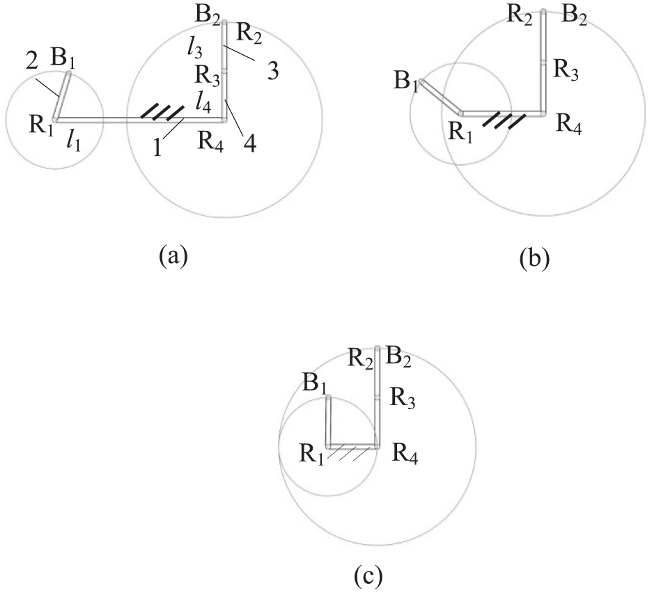
Assembly condition of planar 4R mechanism with motion and locking modes: (a) planar 4R mechanism can not be assembled, (b) planar 4R mechanism can be assembled normally, And (c) planar 4R mechanism with locking mode can be assembled.
Specifically, when the curve of point B1 on link 2 in Figure 2(b) passes through the axis of the revolute pair R4, the assembly of point B1 on link 2 and point B2 on coupler 3 can coincide with the rotational center of the revolute pair R4, as shown in Figure 2(c). In this configuration, point B1 coincides with the rotational center of the revolute pair R4, and the entire kinematic chain R4R3R2 can rotate around the revolute pair R4.
Based on the four-bar mechanism with locking and motion modes shown in Figure 1, it can be seen that the end point B2 of the kinematics chain R4R3R2 passes through the rotation center of the rotating pair R4, and the end point B1 of the kinematics chain R1 can also pass through the rotation center of the rotating pair R4, thus assembling a planar four-bar mechanism that can be in a folded state, that is, the position where the axis of the rotating pair of R2 and R4 coincide, thus achieving the transformation of locking and motion modes.
Difference between locking mode and dead center mode
The parallelogram mechanism shown in Figure 1(c) has its link 2 in a locking mode configuration, which is fundamentally different from the dead-center configuration of a typical planar four-bar mechanism. The simplified diagram of the mechanism in Figure 1(c) is illustrated in Figure 3(a).

3R kinematic chain in constraint singular configuration and dead point configuration of planar 4R mechanism: (a) locking mode and (b) “dead point” configuration.
Figure 3(a) shows the coupler 3 in a locking mode. The screw system of the mechanism in Figure 3(a) is

In equation (1), a
i
, b
i
, and c
i
represent the dual part of the screw of the i-th rotational pair, respectively. The velocity of the end of kinematic chain R4R3R2 can be expressed as

The velocity of the end of kinematic chain R1 can be expressed as

The velocity constraint are shown in equations (4)–(6)


The velocity constraint equations (5) and (6) indicates that the velocity of the end of kinematic chain R4R3R2
Equation (5) is factored which is leads to equations (7) and (8)

or

In the configuration shown in Figure 3(a), the direction of
However, the kinematic chain R4R3R2 shown in Figure 3(a) requires the rotational pair R3 to produce rotation, that is,
Figure 3(b) shows the coupler 3 in the dead center configuration. The twist system of the mechanism in Figure 3(a) is

Similarly, the velocity constraint are shown in equations (10)–(12)


Similarly, for the kinematic chain R4R3R2 shown in Figure 3(b), to leave the dead center configuration of the mechanism, rotation is required to be generated by the rotational pair R3, that is,
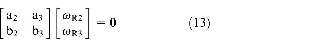
Based on the mechanism configuration shown in Figure 3(b) and in conjunction with equation (9), it can be inferred that [a2, b2]T in equation (13) is linearly related to [a3, b3]T. Therefore, the coefficient matrix in equation (13) is linearly dependent and
The velocity of the end of the kinematic chain R4R3R2
In summary, under both the locking mode configuration and the dead center configuration, the velocity at the end of the kinematic chain R4R3R2 is different in direction from the velocity at the end of the kinematic chain R1, and both velocities should be zero in these two cases. The locking mode configuration analyzed in this article differs from the dead center mode in that it cannot achieve the motion of a specified component by changing the drive settings. The locking mode configuration analyzed in this article can leave the locking mode configuration, only when the velocities of the two ends of the kinematic chain are the same.
The point on the coupler point curve of the 4R mechanism is a double point
The velocity direction of the coincide point at the ends of the two kinematic chains of the planar 4R mechanism determines the configuration of the mechanism during the transition between motion and locking modes. Specifically, when constructing a mechanism with locking and motion mode by using coupler of a planar 4R mechanism as a kinematic chain. The velocity direction of the coupler, that is the tangent direction of the coupler point curve of the 4R mechanism, determines the configuration when the mode of the mechanism transforms from locking mode to motion mode.
When the point on the coupler point curve of the 4R mechanism is a double point, the tangent direction of the coupler point curve may not be unique.
As shown in Figure 4, the planar 4R mechanism consists of four links with lengths l1 = 200 mm, l2 = 50 mm, l3 = 220 mm, and l4 = 30 mm, respectively. That is, l1 + l2 = l3 + l4, and link 1 serves as the frame. As shown in Figure 4(b) and (d), the points C2 and C4 on the curve of coupler point C have two tangents

The coupler point curve of planar 4R mechanism has two double points: (a) coupler point has one tangen, (b) coupler point has two tangents I, (c) coupler point has two coincide tangents, and (d) coupler point has two tangents II.
The curve of coupler point D of the planar 4R mechanism is shown in Figure 5. In the mechanism configuration shown in Figure 5(a), the curve of coupler point D coincides with the axode of the coupler 3. At this time, the moving speed of point D1 on coupler 3 is 0. The literature
17
refers to this point on the curve of coupler point as a cusp, where there are two coincident tangents

The coupler point curve of planar 4R mechanism has a double point and a cusp: (a) coupler point has two coincide tangents, (b) coupler point has two tangents, (c) configuration I is close to double point of coupler point curve, and (d) configuration II is close to double point of coupler point curve.
In the mechanism configuration shown in Figure 5(b), point D2 on the coupler point curve has two tangents τ6 and τ7, indicating that the mechanism is in a constrained singular configuration. Comparing with Figure 5(b) and (d), it can be found that points D2 and D4 in the mechanism configurations of Figure 5(b) and (d) correspond to two mechanism configurations, while points D2 has only one tangent, indicating that the mechanism is in a general configuration. The point D2 in the configuration of the mechanism shown in Figure 5(b) has two tangents, which correspond to one type of mechanism configuration, namely the constrained singular configuration of the mechanism.
The point on the coupler point curve is a threefold points
Specifically, as shown in Figure 6(d), the curve of coupler point E has a threefold Point E4. The dimensions of this mechanism are l1 = 100 mm, l2 = 150 mm, l3 = 100 mm, and l4 = 150 mm. The distance from point E to the rotational pair R2 is 25 mm. As shown in Figure 6(d), Point E4 coincides with the instantaneous center of coupler 3, and the point E4 on the coupler point curve has a cusp point. The mechanism shown in Figure 6(c) could transform to the motion mode shown in Figure 6(b) passing the common mechanism configuration as shown in Figure 6(d). Point E4 is a threefold point, and its trajectory has two tangents,

The coupler point curve of planar 4R mechanism is a threefold point which is constructed by a cusp and a common point: (a) coupler point has one tangent I, (b) coupler point has two tangents, (c) coupler point has one tangent II, and (d) coupler point has 3 tangents.
A method for constructing a four-bar mechanism with a threefold points on the coupler point curve is presented in Hernandez et al., 18 as shown in Figure 7(a). Point F1 represents the threefold point on the coupler point curve. By combining the mechanism configurations shown in Figures 7(b) to (d), it can be observed that the configuration depicted in Figure 7(a) is in a motion bifurcation state and can be transformed into the configurations shown in Figure 7(c) and (d). Meanwhile, the mechanism configuration shown in Figure 7(b) is not near the motion bifurcation configuration. When the mechanism moves from the configuration shown in Figure 7(b) to a position where the point F2 of the link coincides with F1 in Figure 7(a), the motion of the mechanism does not exhibit bifurcation. When the mechanism moves from the configurations shown in Figure 7(c) and (d) to a position where the points F3 and F4 coincide with F1 in Figure 7(a), the motion of the mechanism exhibits bifurcation.
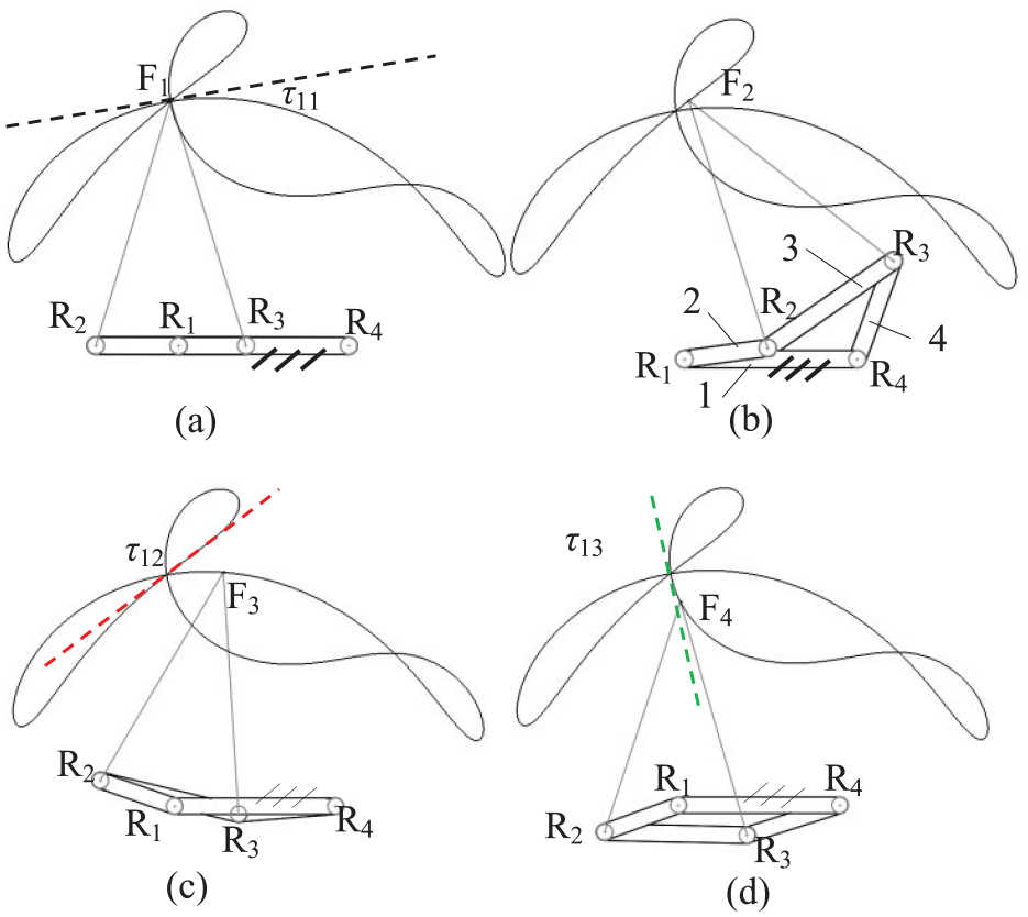
The coupler point curve of planar 4R mechanism is a threefold point which has three tangent lines: (a) coupler point has 3 tangents I, (b) configurations close to threefold coupler point, (c) coupler point has 3 tangents II, and (d) coupler point has 3 tangents III.
Synthesis a Planar 7R mechanism with locking and motion mode
According to the curve of coupler point F of 4R mechanism in Figure 7, a planar 7R mechanism can be constructed as shown in Figure 8. A point G1 on the base in Figure 8(a) is taken as the rotation center of the rotational pair R5. The motion chain R5R6R7 is connected to point G1 on coupler 3 in Figure 7(a), and the rotation center of the rotating pair R7 coincides with point G on coupler 3. As shown in Figure 8(c), under this mechanism configuration, the velocity direction of the end point G3 of the kinematic chain R5R6R7 is the same as the direction of the trajectory tangent τ12 of point G3 on coupler 3, allowing point G3 to undergo slight displacement, thereby leaving the singular configuration and achieving the transformation between locking and motion modes of coupler 3. As shown in Figure 8(e), under this mechanism configuration, the velocity direction of the end point G5 of the kinematic chain R5R6R7 is the same as the direction of the trajectory tangent τ13 of point G5 on coupler 3, allowing point G5 to undergo slight displacement, thereby leaving the singular configuration and achieving the transformation between locking and motion modes due to the kinematic chain R5R6R7 could rotate freely. This results in a mechanism with six configurations that transition from locking mode to planar 7R motion mode.
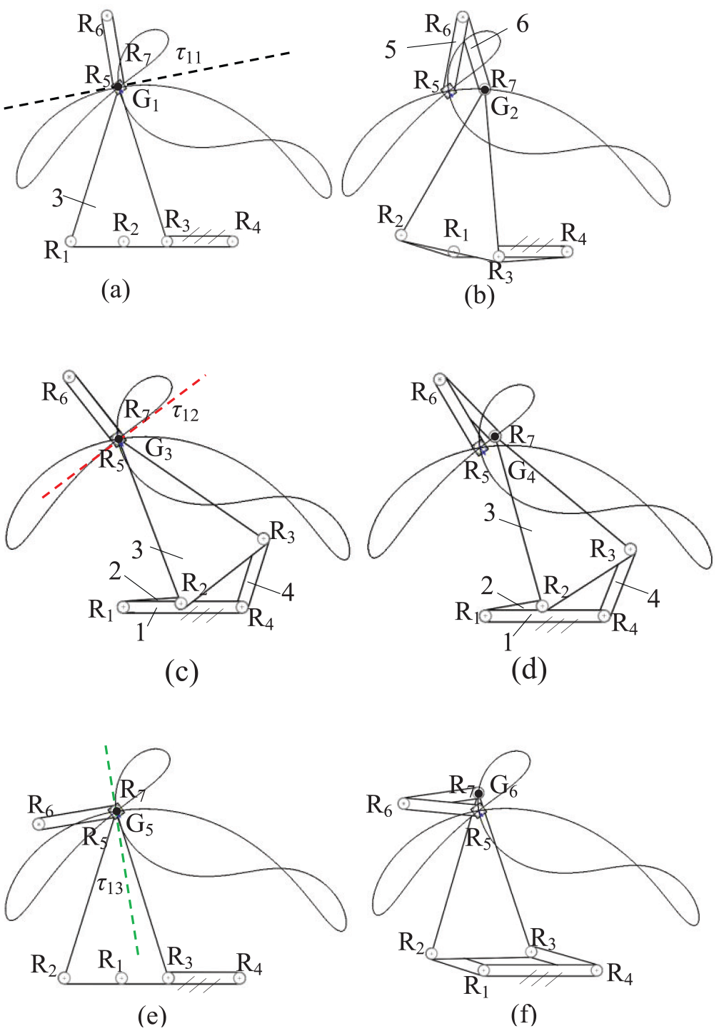
Planar 7R mechanism with two locking modes: (a) motion mode transform configuration I, (b) unlocking configuration I, (c) motion mode transform configuration II, (d) unlocking configuration II, and (e) motion mode transform configuration III, (f) unlocking configuration III.
The coupler 3 of the mechanism shown in Figure 8 has two locking modes, as illustrated in Figure 8(a) and (c), where the coupler 3 is in two different configurations. When the velocity direction of the end point G of the kinematic chain R5R6R7 does not coincide with the tangent of the coupler point curve of the coupler 3, the coupler 3 is in a locking mode.
If the axes of the joints in the R5R6R7 chain become coplanar, this chain imposes one constraint on the coupler 3 and could locks its motion, and the mechanism cannot escape the locking mode. When the whole of the mechanism is in a singular state, the mechanism can escape the locking mode and continue its motion.
Spherical 7R mechanism with motion and locking modes
Transition between motion and locking modes
The method for synthesizing a planar 7R mechanism with locking and motion modes can be applied to synthesize a spherical 7R mechanism with locking and motion modes. As shown in Figure 9, point H1 on the coupler point curve of R1R2R3R4 Spherical 4R loop is a non-singular point, and there is only one tangent line at this point on the link curve. In the mechanism configuration shown in Figure 9(a), the axes of the rotational pairs R7 and R5 coincide, and the kinematic chain R5R6R7 can rotate freely. At this time, the spherical 4R loop R1R2R3R4 is in a locking state. The direction of the velocity

Spherical 7R mechanism with one motion mode and one locking mode: (a) locking mode, (b) motion mode transform configuration I, (c) motion mode transform configuration II, and (d) unlocking mode.
Assembly conditions with motion and locking modes
Based on the assembly conditions of the planar 7R mechanism with motion and locking modes, the assembly conditions of the spherical 7R mechanism with motion and locking modes can be similarly derived, as shown in Figure 10. The spherical workspace of the kinematic chain R5R6R7 allows the point I1 on the link 6 to rotate around the axis R6 as a fixed axis, resulting in a circle. This circle rotates around the axis R5, forming a spherical surface, which represents the spherical workspace that the point I1 at the end of the kinematic chain R5R6R7 can reach. In Figure 10, the angles between the rotational pairs R5 and R6, and R6 and R7 are both 90°, so the point I1 at the end of the kinematic chain R5R6R7 can reach the entire spherical surface. The curve of the coupler point I2 on the coupler 3 of the spherical 4R mechanism is shown as the black curve in Figure 10(b). The workspace reachable by point I3 in the mechanism shown in Figure 10(c) is the intersection of the workspace reachable by the point I1 at the end of the kinematic chain R5R6R7 and the workspace reachable by the point I2 on the coupler of the spherical 4R mechanism R1R2R3R4, which is represented by the black curve which is the same as the coupler point curve of the spherical 4R in Figure 10(b).
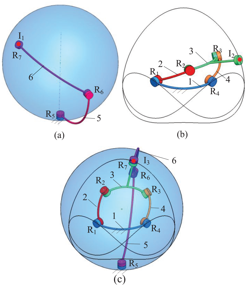
Schematic diagram of assembly conditions for spherical 7R mechanism: (a) spherical 3R kinematic chain, (b) coupler curve has 3 double points, (c) spherical 7R mechanism at unlocking mode.
Coupler point curve has a double point during mode transformation
The curve of the coupler point I2 on the coupler 3 of the spherical 4R mechanism R1R2R3R4 in Figure 10(b) is shown in Figure 11. In Figure 11(a), J1 is a double point, and there are two tangents at the point J1 on the coupler point curve, corresponding to two different mechanism configurations. Specifically, when the velocity direction of point J1 is along the tangent

The coupler point curve of spherical 4R mechanism has three double points: (a) coupler point has two tangens I, (b) coupler point has two tangens II, (c) coupler point has two coincidetangens I, and (d) coupler point has two coincide tangens II.
When the spherical 4R mechanism is in the folded configuration, the point on the coupler is generally the double point on the coupler point curve. As shown in Figure 12(a), point K1 on the coupler point curve has double point when the spherical 4R mechanism is in the folded configuration. Point K1 on the coupler point curve of the spherical 4R mechanism has two coincident tangents, τ18 and τ18′.

The coupler curve of spherical 4R mechanism has 2 kinds of double point: (a) coupler point has two coincide tangens, (b) coupler point has two tangens I, (c) coupler point has two tangens II.
When the mechanism moves to the configuration shown in Figure 12(b), coupler point K reaches point K2, which is the double point on the coupler point curve. There are two non-coincident tangents to its trajectory. In the configuration of the mechanism shown in Figure 12(b), one tangent to the curve of the coupler point K2 is τ19. The other mechanism configuration corresponding to point K2 on the link trajectory is shown in Figure 12(c). In this configuration, another tangent to the curve of the coupler point K3 is τ19′.
Based on the two double points on the coupler point curve shown in Figure 12(a), the kinematic chain R5R6R7 is set up, ensuring that the rotational pairs R5 and R7 are collinear, and their axes pass through point K1 on coupler 3 in the mechanism configuration of Figure 13(a). Figures 13(a) and (d) depict the mechanism configurations of the spherical 4R loop R1R2R3R4 transitioning from the locking mode to the motion mode. As shown in Figure 13(a) and (d), when the curve of the coupler point L1 on the coupler 3 of the spherical 4R loop R1R2R3R4 is tangent to τ20, the tangent line τ20 is perpendicular to the folding plane of the spherical 4R loop R1R2R3R4. In this configuration, when the tangent line of the curve of the point L1 on the kinematic chain R5R6R7 coincides with the tangent line τ20, the kinematic chain R5R6R7 can leave the folded configuration, and the coupler 3 can achieve the transition to the motion mode.
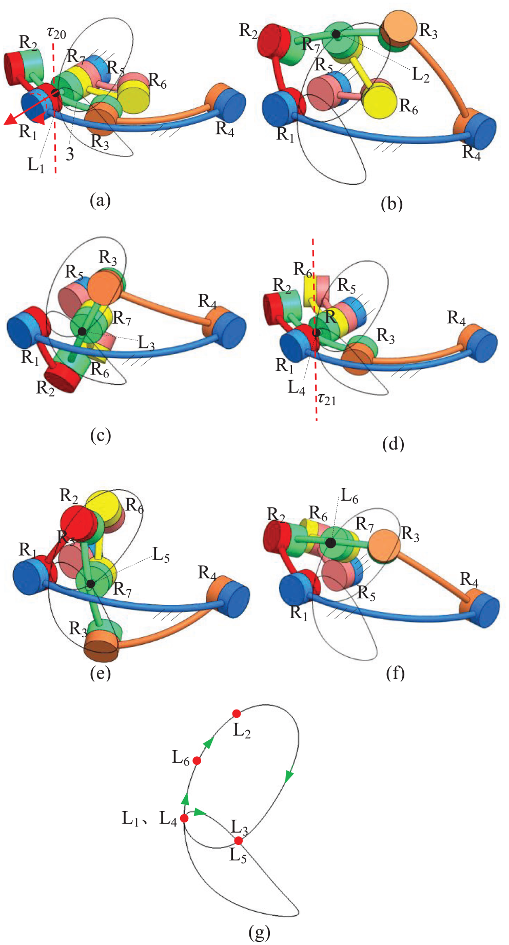
Spherical 7R mechanism has two motion modes and one locking mode: (a) motion mode tranform configuration I, (b) unlocking mode configuration I, (c) unlocking mode configuration II, (d) motion mode tranform configuration II, (e) unlocking mode configuration III, (f) unlocking mode configuration IV, and (g) coupler point on the coupler curve which are corresponding to mechanism configurations.
Under the mechanism configurations of Figure 13(c) and (e), points L3 and L5 are double point on the coupler point curve. At this time, there are two different mechanism configurations, neither of which can be switched between motion mode and locking mode.
Figure 13(a) shows the mechanism configuration during the counterclockwise rotation of the rotational pair R1, moving from the mechanism configuration shown in Figure 13(b) to (d), the mechanism undergoes motion bifurcation in the configuration of Figure 13(d), allowing it to move to the configurations of Figure 13(e) and (f). The mechanism configuration from Figure 13(a) to (f) are corresponds to the point L1 to L6 on the coupler point curve in Figure 13(g), respectively.
The point on the coupler point curve of spherical 4R mechanism is a threefold point
Under the folded configuration of the spherical 4R mechanism, the coupler possesses two non-coincident instantaneous axes of rotation. If a point on the coupler lies on its instantaneous axis of rotation, and this point is a cusp, it is a special type of double point. Given that the mechanism is in a folded configuration, this point inherently serves as a double points, thereby rendering it a threefold point on the coupler point curve at this moment.
As shown in Figure 14(a), there is only one tangent line to point M1 on the coupler 3 of the spherical 4R mechanism. When the mechanism moves to the folded configuration shown in Figure 14(b), one instantaneous rotation axis

The coupler point curve of spherical 4R mechanism has a threefold point which is constructed by a cusp and a common point: (a) coupler point has one tangent and (b) coupler point has 3 tangents, 2 of them are coincide.

Spherical 7R mechanism with one locking mode and one motion modes: (a) motion mode transform configuration I, (b) motion mode transform configuration II, (c) motion mode transform configuration II, (d) motion mode transform configuration IV.
As shown in Figure 15(a) and (b), when the trajectory tangent of point N on the coupler 3 of the spherical 4R mechanism R1R2R3R4 is along τ24, the tangent τ24 is perpendicular to the folding plane of the spherical 4R loop R1R2R3R4. Under this configuration, when the trajectory tangent of the end point N of the kinematic chain R5R6R7 coincides with the tangent τ24, the kinematic chain R5R6R7 can leave the folding configuration, and the coupler 3 can achieve a change in motion mode.
As shown in Figure 15(c) and (d), when the trajectory tangent of point N on the coupler 3 of the spherical 4R mechanism R1R2R3R4 is along τ25, in this configuration, when the trajectory tangent of the end point N of the kinematic chain R5R6R7 coincides with the tangent τ25, the kinematic chain R5R6R7 can leave the folded configuration, and the coupler 3 can achieve a change in motion mode.
The specific process of the mechanism transitioning from the locking mode to the motion mode is shown in Figure 16(h). The mechanism transforms from the configuration shown in Figure 16(a), corresponding to point N1 on the link trajectory in Figure 16(h), to the configuration shown in Figure 16(b), corresponding to point N2 on the link trajectory in Figure 16(h).

Mode transformation of spherical 7R mechanism from locking mode to motion modes: (a) motion mode transform configuration I, (b) unlocking mode configuration I, (c) unlocking mode configuration II, (d) motion mode transform configuration II, (e) motion mode transform configuration III, and (f) coupler point on the coupler curve which are corresponding to mechanism configurations.
Figure 16(a) depicts the mechanism configuration, where during the counterclockwise rotation of the revolute pair R1, the mechanism sequentially transforms from the configurations shown in Figure 16(b) to (g), corresponding to the link trajectories N1 to N7 in Figure 16(h).
Figure 17(a) illustrates the spherical 4R mechanism with angles α14 = 90°, α12 = 30°, α23 = 60°, α34 = 60°, α27 = 45°, and α37 = 45°. The curve of the coupler point P of this spherical mechanism has a special threefold point. The mechanism shown in Figure 17(a) is in a constrained singular configuration, leading to motion bifurcation. Under normal constrained singular configuration, the point on the coupler point curve has a double point. When the mechanism transforms to the configuration shown in Figure 17(b), the point P2 on the coupler point curve coincides with the double point on the curve of coupler point P1 in the configuration shown in Figure 17(a). Based on the threefold point on the coupler point curve, a spherical 7R mechanism with two locking modes can be designed.

The coupler point curve of spherical 4R mechanism has a threefold point which has three tangent lines: (a) configuration I is corresponding to coupler point has 3 tangents, and (b) configuration II is corresponding to coupler point has 3 tangents.
As shown in Figure 18(a), the motion R5R6R7 is set up so that the axes of the rotational pairs R5 and R7 coincide and pass through the threefold point P1 of the coupler point curve in Figure 17(a). In the mechanism configuration shown in Figure 18(a), the velocity direction of point P3
Spherical 7R mechanism has two locking modes and one motion modes: (a) motion mode transform configuration I, (b) unlocking mode configuration I, (c) motion mode transform configuration II, (d) unlocking mode configuration II, (e) motion mode transform configuration III, (f) unlocking mode configuration III, (g) locking mode configuration I, and (h) locking mode configuration II.
Similarly, for the mechanism configurations shown in Figure 18(c) and (e), the velocity directions of points P
The mechanism configurations shown in Figure 18(g) and (h), where the velocity directions
Coupler point curve has a quadruple point during mode transformation
As shown in Figure 19(a), the structural parameters of the spherical 4R mechanism are α14 = 60°, α12 = 30°, α23 = 60°, α34 = 30°, α27 = 90°, and α37 = 90°. The spherical 4R mechanism is in a folded configuration, and it possesses two variable-axis motion modes. 16 The point Q1 on the coupler 3 is located perpendicular to the plane of the mechanism’s folded configuration and passes through the normal line of the mechanism’s rotation center as shown in Figure 19. When the mechanism has two folded configurations as shown in Figure 19(a) and (b), the points Q1 and Q2 on the coupler are at the same point in both folded configurations.

The coupler point curve of planar 4R mechanism has a quadruple point which has four tangent lines: (a) configuration I is corresponding to coupler point has 4 Tangents, and (b) configuration II is corresponding to coupler point has 4 tangents.
In the folded configuration of the mechanism, as Figures 17 and 18, the point on the couple is either a double point or threefold point on the coupler point curve. When the point Q on the coupler passes through the instantaneous axis of rotation of the coupler in the folded configuration, it becomes a threefold point on the coupler point curve. In Figure 19, the point Q on coupler 3 is not located on the folding plane of the mechanism, thus it is a double point on the coupler point curve. It can be observed that the mechanism in Figure 19 has two folded configurations, and the point Q on coupler 3 is a quadruple point on the coupler point curve the mechanism.
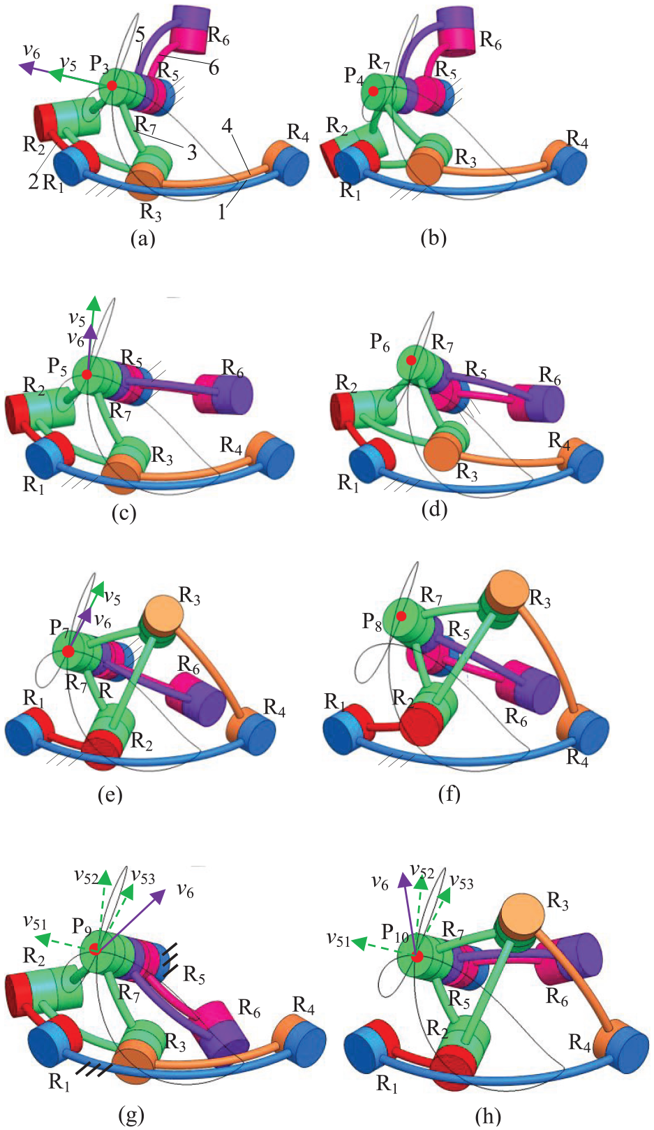
As shown in Figure 20, the motion R5R6R7 is set to ensure that the axes of the rotational pairs R5 and R7 coincide and pass through the point Q1 on the coupler point curve in Figure 19(a). In the mechanism configuration shown in Figure 20(a), the velocity direction of point Q3 on coupler 3 is the same as that of point Q3 on link 5. At this time, the mechanism is in a transformation configuration between locking and motion modes, and can move to the mechanism configuration shown in Figure 20(b). Similarly, for the mechanism configurations shown in Figure 20(c), (e), and (g), the velocity direction of points Q5, Q7, and Q9 on coupler 3 is the same as that of point Q on link 5, allowing it to move to the mechanism configurations shown in Figure 20(d), (f), and (h).

Spherical 7R mechanism featuring two locking modes and two motion modes: (a) motion mode transform configuration I, (b) unlocking mode configuration I, (c) motion mode transform configuration II (d) unlocking mode configuration II, (e) motion mode transform configuration III, (f) unlocking mode configuration III, (g) motion mode transform configuration IV, (h) unlocking mode configuration IV, (i) locking mode configuration I, and (j) locking mode configuration II.
The configurations of the mechanisms shown in Figure 20(g), (h), and (j), where the velocity directions of the four motion bifurcations at point Q on coupler 3 are all different from the velocity direction of point Q on link 5, indicating that the mechanism is in a locking mode. The kinematic chain R5R6R7 possesses one local rotational degree of freedom, allowing it to freely rotate around the axis of the rotational pair R5.
Analysis of the transformation of motion mode of spherical 7R mechanism
As shown in Figure 21(b), for the spherical 7R mechanism, the point T on the coupler point curve coincides with the instantaneous rotation center Saxode of the coupler 3 as Figure 21(a).
19
It can be observed that the velocity
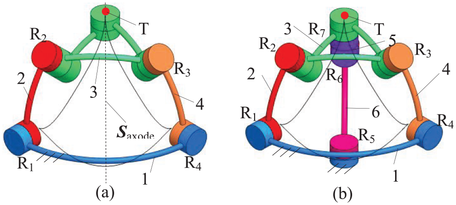
Spherical 7R mechanism with one locking mode and one motion mode: (a) coupler point has two coincide tangents and (b) locking mode configuration.
The angle between the axis of the R
i
axis of the rotational pair and the axis of the R
j
axis in Figure 22(b) is α
ij
. Figure 22(b) The spherical 4R loop R1R2R3R4 with α12 = π/4, α23 = π/3, α34 = π/4, α41 = π/2 is shown in Figure 22(a). The kinematic chain R5R6R7 is shown in Figure 21(b), where α27 = π/4, α37 = π/4, α76 = π/2, and α65 = π/2. In Figure 22(b), when the four rotational pairs R1, R2, R3, and R4 of the spherical 4R mechanism correspond to the twist elements


Twist of spherical 7R mechanism has one locking mode and one motion mode: (a) kinematic screw of spherical 4R and (b) kinematic screw of spherical 7R.
The first-order kinematic constraint equation for the spherical 5R loop of R1R2R7R6R5 in Figure 22(b) is

Equation (16) is obtained by combining (14) and (15)

In Figure 22(b), because each moment part of the screws equals zero which could be ignored in order to simplify the synthesis. And then, the screw of the rotation axes in the coordinate system O-XYZ are
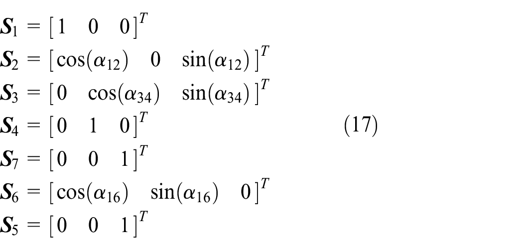
Substituting the twist of each joint in equation (17) into equation (16), equation (18) is obtained.

After simplifying, equation (19) is obtained.

The rank of the coefficient matrix of equation (19) is 5. According to the analysis of equation (19), the mechanism have 2 degrees of freedom, and the mechanism undergoes motion bifurcation at any configurations when the axis of rotating pair R5 coincides with the axis of rotating pair R7. However, it is not true. By analyzing the velocity constraint of the mechanism in equation (19), it is not possible to determine the bifurcation configuration of the mechanism’s motion, therefore it is necessary to analyze the acceleration constraint of the mechanism.
Take the derivative of equation (14) with respect to time t yields

Substituting equation (14) into equation (20) yields

Take the derivative of equation (15) with respect to time t yields

Substituting equation (17) into equation (15) yields ω6 = 0, substituting it into equation (22) yields
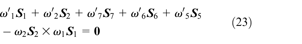
Substitute equation (17) into equations (21) and (23), equation (24) is obtained by combining equations (21)–(23)

After simplification
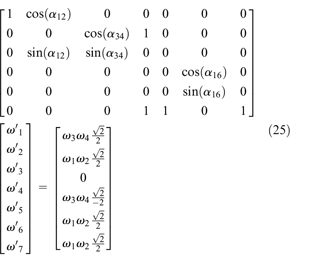
When equation (25) has a solution, it is necessary to ensure that the rank of the coefficient matrix is the same as that of the augmented matrix. When the mechanism shown in Figure 22(b) undergoes motion bifurcation, the mechanism must have at least 2 degrees of freedom. According to observation, only the rank of matrix in equation (26) affects the rank of the coefficient matrix and the augmented matrix in equation (25)

When the determinant of the matrix in equation (26) is zero, the rank of both the coefficient matrix and the augmented matrix of the linear equation system (25) is 5. At this point, the mechanism has two instantaneous degrees of freedom and is in a motion bifurcation configuration. The determinant of the matrix in equation (26) is

According to equation (19), we can obtain equation (28)

By combining equation (28) with algebraic expression (27) yields

According to equation (29), when α16 is either −45° or 135°, the rank of both the coefficient matrix and the augmented matrix of the linear equation system (25) is 5. At this point, the mechanism possesses two instantaneous degrees of freedom and is in a motion bifurcation configuration.
Conclusion
A planar 4R mechanism and a spherical 4R mechanism are equipped with a folding 3R kinematic chain on their links, thereby integrating a planar 7R and spherical 7R mechanism with both motion and locking modes. Based on the tangent of the coupler point curve, the configuration characteristics for switching between the mechanism’s motion and locking modes are determined. Based on the coupler point curve of the planar 4R mechanism with double and threefold point, and the coupler point curve of the spherical 4R mechanism with threefold and quadruple point, a spherical 7R mechanism with different mode-switching configurations is designed.
When the point on the curve of coupler point of the spherical 4R loop is a cusp, it is difficult to determine the tangent of the trajectory. The screw theory is used to analyze the first-order and second-order motion constraint equation of the spherical 7R mechanism, and determine the transformation configuration of the mechanism with motion and locking modes. When it is necessary to analyze the tangent of the multiple points of on the coupler point curve of the 4R mechanism, the 7R double loop mechanism can be constructed using the method proposed in this paper, and the screw theory is used to determine the transformation configuration of the mechanism’s motion mode, thereby determining the direction of tangents of the multiple points on the curve of coupler point.
Footnotes
Handling Editor: Maja Čavić
Funding
The author(s) disclosed receipt of the following financial support for the research, authorship, and/or publication of this article: This project is supported by Shaanxi Provincial Natural Science Foundation (Grant No. 2024JC-YBMS-295).
Conflicting interests
The author(s) declared no potential conflicts of interest with respect to the research, authorship, and/or publication of this article.