
Abstract
Center alignment devices play a crucial role in industrial manufacturing and assembly, but they have certain drawbacks, including instability, complexity, and high production costs. To address these issues, this study introduces an alternative planar-based linear contact-type adaptive center-alignment device (Linear Contact Adaptive Centering Device, LCACD) that can achieve center alignment for a specific range of shaft diameters. The LCACD is based on an enhanced six-bar mechanism and features a unique rhombus-like structure that generates equivalent forces from each clamping point. To evaluate the performance and effectiveness of the proposed design, this study conducted a comprehensive analysis of the LCACD. First, the LCACD underwent kinematic analysis, where the displacement, velocity, and acceleration of the clamping point were calculated and analyzed to determine its linear range. Then, the adaptability and stability of the LCACD was validated from simulations and clamping experiments. The experimental results show that the LCACD can precisely position shaft-like components within 25%–40% of the total stroke, at a clamping error <1%. Both theoretical and empirical evidence suggests that the LCACD can attain a high degree of adaptability and precision with the use of a simplified control mechanism.
Keywords
Introduction
The center alignment device is a precision positioning and alignment tool widely used in manufacturing and assembly processes. It plays a crucial role in clamping, guiding, and anti-impact, ensuring that the central axis of one shaft is accurately aligned to another with high accuracy and quality, in both manufacturing and assembly. Center alignment devices have wide-ranging applications, including automotive,1–3 aerospace,4,5 medical devices,6,7 electronic,8–10 and mechanical manufacturing.11–13
Center alignment devices are classified into contact and non-contact types based on their interaction with target objects. 14 Contact-type center alignment devices achieve alignment and clamping by applying force to the target object, utilizing the concept of compliant motion to describe the contact forces generated through interaction between the device and the target. 15 The compliant motion in contact-type center alignment devices can be further divided into active and passive compliance. Currently, parallel clamping mechanisms composed of elastic sheets or flexible materials are widely used in passive compliant center alignment devices. Chavan-Dafle et al. enhanced the stability of a parallel gripper by integrating two V-shaped elastic strips at the end-effector. 16 Under clamping force, these strips undergo elastic deformation, converting the original two-point contact into a multi-point contact configuration, thereby improving clamping stability. Similarly, Bircher et al. developed a parallel two-finger robotic gripper with a reconfigurable linkage structure, enabling object repositioning and reorientation. 17 Although passive compliant center alignment devices can meet the precision alignment requirements for shaft-like components, they still have limitations in clamping force control, making it difficult to precisely regulate load during the clamping process.
Another emerging type of passive compliant center alignment device is the underactuated manipulator.18,19 Compared to conventional six-degree-of-freedom (6-DOF) robotic manipulators, underactuated manipulators can adapt to objects of various sizes and shapes. However, they suffer from insufficient grip strength and limited alignment accuracy. Active compliant alignment devices integrate force feedback mechanisms into the alignment system by incorporating tactile sensors, 20 force, 21 and torque sensors 22 to measure the alignment state. Venter and Mazid developed a capacitive tactile sensor that monitors object slippage through the nonlinear relationship between capacitance and applied force. 23 Tang et al. utilized a force-torque sensor to evaluate the relative posture of a pin and hole under a three-point contact condition. 24 By analyzing and compensating for misalignment, their method directly eliminates positional errors, thereby achieving precise alignment. A key advantage of active compliant alignment devices is their ability to sense real-time contact forces between the gripper and the workpiece, dynamically adjusting the clamping force based on actual conditions. However, these systems also present significant challenges, including high cost, complex structural design, intricate control algorithms, and lower stability.
Unlike contact-based center alignment devices, non-contact center alignment devices benefit from the advantages of image processing and machine vision technologies.25,26 Conventional mechanical inspections are limited in terms of precision and flexibility, making them less effective than machine vision. Cheng et al. used a depth detection sensor to capture RGB-D images and estimate the grasping posture by integrating RGB and depth information, achieving dense grasping posture prediction. 27 However, machine vision is susceptible to environmental influences and cannot fully capture information from occluded objects. Additionally, it requires significant computational resources. Additionally, laser technology28,29 has also been used to measure the position and posture of objects for alignment, offering the advantage of high precision. However, laser alignment cannot be applied in axially confined spaces. Furthermore, these non-contact alignment technologies require the use of precise sensors and algorithms, which increases both the equipment cost and maintenance cost.
Existing center alignment devices have various limitations in terms of clamping force control, alignment accuracy, stability, cost, and flexibility, making it difficult to achieve ideal alignment results in industrial applications. To address these issues, this study proposes a planar linear contact center alignment device (LCACD). The LCACD can provide stable clamping force using only a single driving power, achieve four-point clamping of the target, and precisely align shaft-like components within a specific size range. Moreover, the proposed LCACD is composed of a purely mechanical structure that does not require sensors or other electronic components, reducing production and maintenance costs, and improving reliability and stability. The LCACD can achieve precise alignment in narrow axial spaces, making it suitable for environments where optical or visual equipment cannot be used. By employing unidirectional drive and contact methods, the LCACD enables alignment of shaft systems. Its compact structure offers a new option for existing alignment technologies. The LCACD has broad application potential in alignment scenarios involving light-sensitive or limited spaces. For example, in the production of optical and medical devices, the LCACD can be used for adjusting optical components and assembling biosensors to ensure the accuracy of the equipment. Through practical applications in these fields, the LCACD can provide efficient positioning and alignment solutions for various industrial needs.
Design and improvement of LCACD
Plane-based structural design
When a shaft is clamped, it requires two orthogonal forces to secure its position. This is typically achieved using two actuators. However, by employing a six-bar mechanism, it is possible to achieve precise alignment of the shaft with only a single actuator. Nevertheless, a six-bar mechanism (Figure 1(a)) can only provide centering and positioning for one specific shaft diameter, which limits its ability to accommodate varying shaft diameters. To solve this problem, a triangle/rhombus mechanism was used to adjust the length of AB (Figure 1(b)), to fit shafts with different diameters (Figure 1(c)). Due to the symmetry of the structure, the discussion can be concentrated on the quarter-structure OADBC (Figure 2(a)).
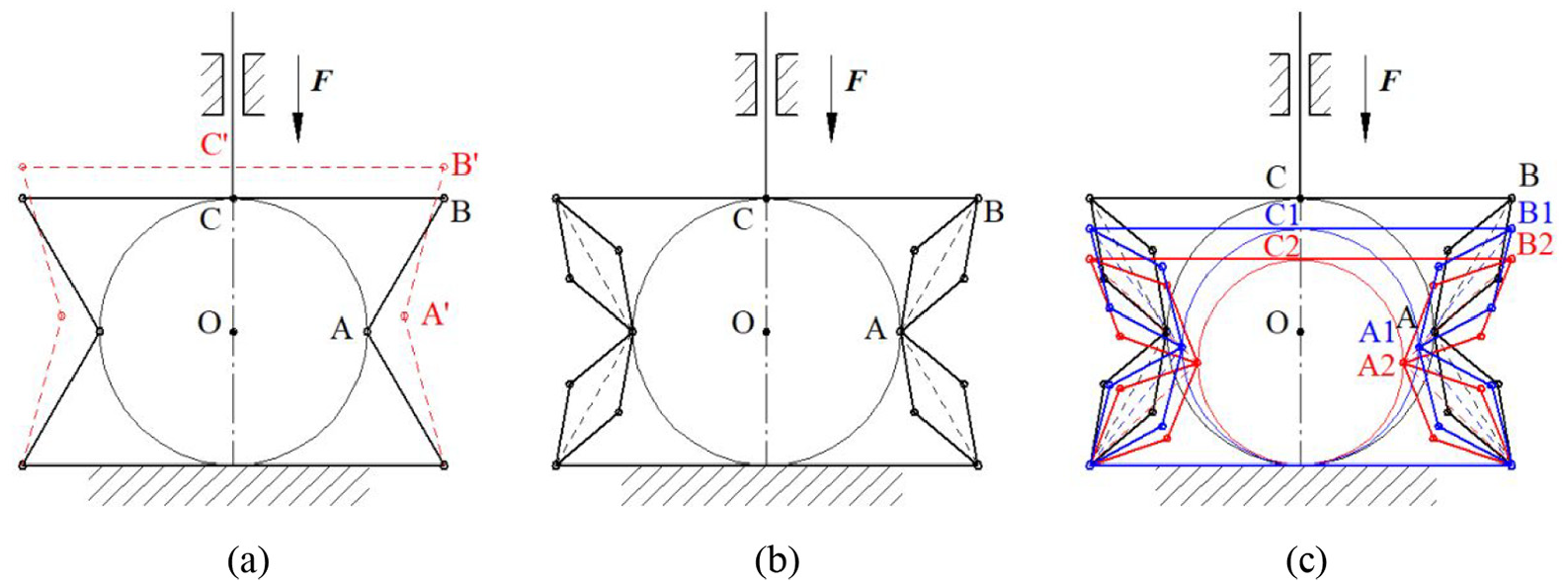
Center alignment device based on six-bar mechanism: (a) the original six-bar mechanism, (b) improved adjustable center alignment device, and (c) positioning axes of different diameters.

Simplified diagram of link-slider mechanism: (a) symmetrical region of improved adjustable centering mechanism, (b) equivalent link-slider mechanism, (c) improved local link-slider mechanism, and (d) motion analysis of OABCDE mechanism.
In previous studies, 30 the OADBC can be simplified as a link-slider mechanism (Figure 2(b)). However, this mechanism consists of four moving links and five lower pairs. According to Gruebler’s Equation, the DOF of OADBC is two. With a single driving unit, the motion of the OADBC becomes uncertain. Therefore, additional moving links are needed to meet the motion requirements.
Improvement of planar mechanism
To ensure the mechanism exhibits definite motion, it is necessary to improve the original design. A new link EF is introduced into the original OADBC configuration, connecting base BC to FG, and replacing link AD with a three-revolute-pair link ADE (Figure 2(c)). This modification transforms the original five-bar mechanism into a revised configuration featuring five moving links and seven lower pairs. Consequently, the improved center alignment device possesses a single degree of freedom. When the number of actuators is one, the motion of this mechanism is determined. To achieve the equidistant movement of Points A and C (relative to Point O) under vertical force, the coordinate derivation for Point A must be established, subject to the following conditions:

This condition indicates that the distance from point O to point A is equal to the distance from point O to point C.

Considering that AD and BC are part of the diamond structure, therefore:

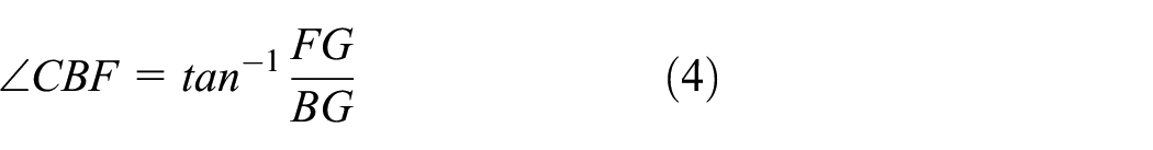
Based on this, a structural analysis is performed on the improved mechanism, and auxiliary line segments BG, DF, DN, and EM are constructed (Figure 2(d)). In prior work, Point C was used as the origin, and OA and OC were used as the x and y axes individually. Then, the position of fixed Point F and moving Point A could be obtained by using the continuous linear trajectory of Point D. Also, the length of EF could be obtained as the radius of Point F. Hence, the lengths of BG, FG, DF, and EF could be calculated based on the given values of AD, BD, and DE.
Therefore, In

In


In


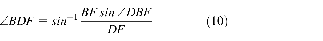
In the four-bar mechanism BDEG,

Due to

From this, it can be concluded that
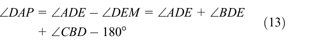
The coordinates of the Point A can be obtained from the geometric relationship as follows
Whereby
Structural data of the LCACD.


Schematic diagram of the motion of the LCACD.
Kinematic analysis of the modified mechanism LCACD
To determine the precise motion of the mechanism, a kinematic analysis of the improved center alignment device (modified mechanism LCACD) is essential. In this section, Point A in mechanism OABCDE is subjected to kinematic analysis. As established in the previous section, Point C serves as the origin of mechanism OABCDE, with OA and OC designated as the x and y axes, respectively. Since the motion of Point A consists of multiple revolute pairs, it is crucial to study the variations in displacement, velocity, and acceleration of Point A in both the x and y directions to ensure the straightness of its motion. Table 2 summarizes the kinematic parameters of the center alignment device and their physical significance.
Explanation of kinematic parameters for Point A.

Motion parameter derivation of Point A
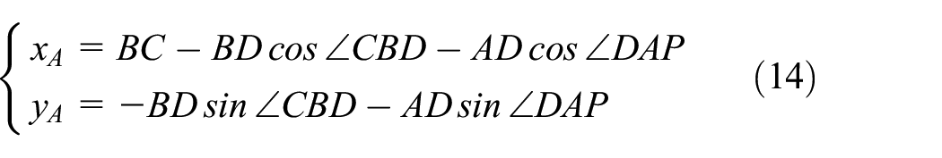
The displacement equations of Point A in the x and y directions can be obtained from equation (14). The velocity equation of Point A is obtained by derivation on the displacement equation of equation (14), see details in Appendix A and B.
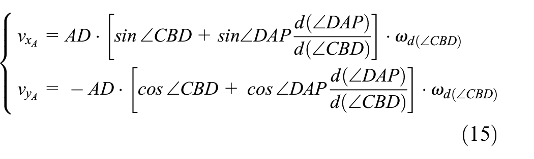
The acceleration equation of Point A is obtained by differentiating the velocity equation of equation (15), see details in Appendix A and B.

Given the complexity of the aforementioned equations, which only account for the linear relationship of Point A in the x and y directions with respect to displacement, velocity, and acceleration, it is crucial to analyze the kinematic behavior of Point A along both the x and y axes.
Analysis of kinematic relationship of Point A on x and y axes
Since the relationship between the x and y directions cannot be directly calculated in the above kinematic equations, and all the variables in the equations are related to ∠CBD, the motion parameters can be evaluated using ∠CBD. By applying the structural data provided in Table 1, the centering capability of the mechanism can be validated as shown below.
Displacement analysis
Taking


Displacement analysis diagram: (a) displacement diagram, (b) displacement error diagram, and (c) displacement comparison between
Calculating the error between
To clearly show the change relationship between
Velocity analysis
Similarly, for the velocity analysis,

(a) Velocity diagram, (b) velocity error diagram, (c) velocity error analysis based on displacement, and (d) velocity error analysis based on angle.
In order to evaluate the centering capability in terms of velocity, the error criterion of velocity is set as
The error between

Where
As shown in Figure 5,
Acceleration analysis
The clamping performance of LCACD is critical to its application potential, as it is directly influenced by the acceleration of Point A. By retaining ∠CBD as the independent variable and varying it from 0° to 90°, the accelerations
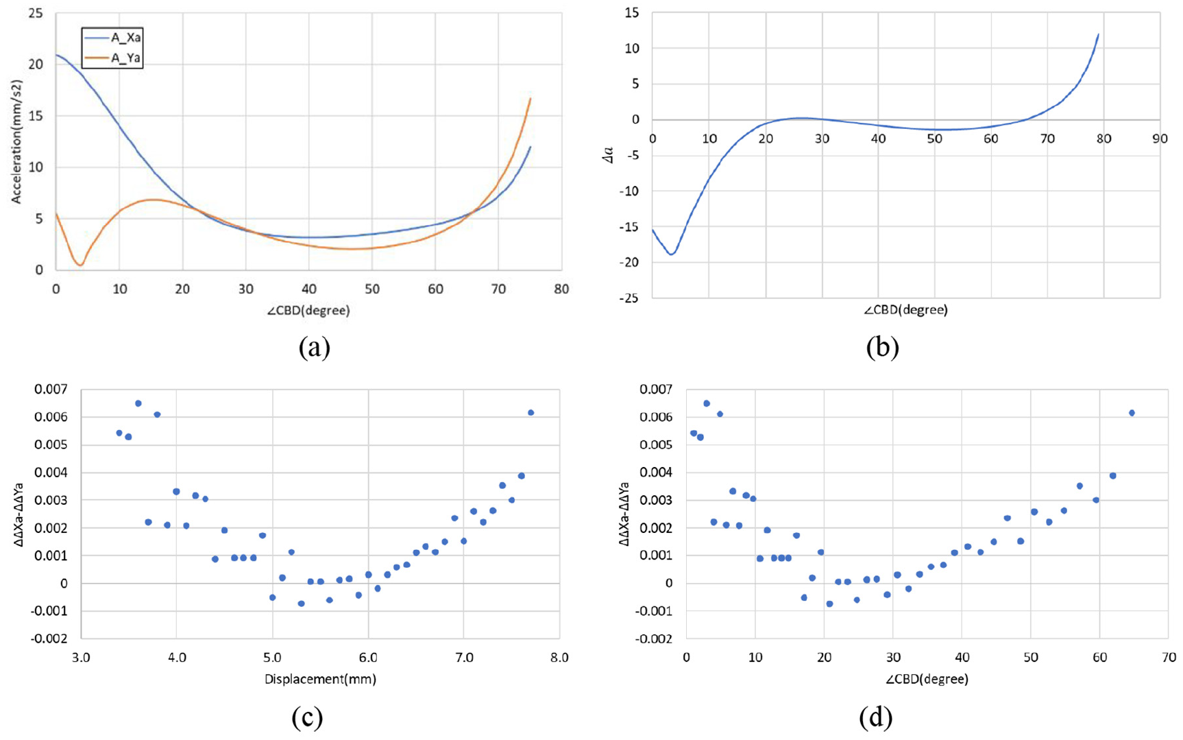
(a) Acceleration diagram, (b) acceleration error diagram, (c) acceleration error analysis based on displacement, and (d) acceleration error analysis based on angle.
To evaluate the centering capability of acceleration, the error criterion of acceleration is set as

The error between

Where
As shown in Figure 6, the error between the accelerations
Analysis and summary of motion parameters at Point A
By analyzing the displacement, velocity, and acceleration of the mechanism’s movable Point A, it is found that ∠CBD is in the range of 20°–40° and that the displacement, velocity, and acceleration of Point A in the x and y directions follow the same trend. This indicates that the LCACD can smoothly clamp shaft segments of different diameters within this movement range.
Simulation and case study
Simulation analysis
To further validate the enhanced centering capabilities of the LCACD, a spreadsheet-based model was developed to simulate its complete motion (Figure 7). This model was utilized to analyze the LCACD’s motion space, identify potential motion constraints and limitations, and evaluate its accuracy and stability.
As shown in Figure 4, when the angle is between 20° and 40°, the displacement of Point A in the X and Y directions maintains a proportional relationship, indicating linear motion. Furthermore, by comparing different states of the LCACD, as illustrated in Figure 7(a)–(c), it is evident that the other clamping points, A′, C, and C′, also exhibit linear motion. Additionally, Figure 7(d) demonstrates that the LCACD achieves stable linear motion within the range of 10–13 mm, confirming its ability to securely hold shafts with diameters of 10–13 mm. Moreover, the results indicate that within the theoretical linear clamping range, the device operates without motion constraints or limitations.

Simulation analysis of motion diagram: (a) state of the LCACD at 20°, (b) state of the LCACD at 30°, (c) state of the LCACD at 40°, and (d) trajectory of contact points in the LCACD state (represented by the thick black line).
CAD case study
Based on the simulation motion diagram in Figure 7, it can be inferred that the LCACD can smoothly clamp shafts with diameters ranging from 10 to 13 mm. To further validate its effectiveness, a CAD model of the mechanism was developed. As shown in Figure 8(a) and (b), an enlarged version of the LCACD was created in SolidWorks, scaled five times larger than the original design, with A and C serving as the clamping points and B as the hinge. For this enlarged LCACD, the theoretical linear clamping range is calculated to be 50–65 mm. To verify its motion characteristics, a dynamic motion analysis of the center alignment device was conducted in SolidWorks, as illustrated in Figure 8(c). The results indicate that the enlarged LCACD retains the clamping characteristics of the original design and achieves stable clamping within the specified range.

3D model of the LCACD and simulation: (a) front view, (b) side view, and (c) dynamic analysis.
Furthermore, this study conducted a motion simulation of the LCACD using the motion analysis module in SolidWorks. By moving position BC upward, the displacement-time curves of the clamping point A in both the X and Y directions were obtained. As shown in Figure 9, the two lines represent the displacement of the LCACD’s clamping point in the X and Y directions, respectively. From the results in Figure 9, it can be observed that when the clamping size ranges from 50 to 65 mm, the displacement of Point A in both X and Y directions remains nearly identical. This indicates that the simulated clamping range of the LCACD is consistent with the theoretical calculations.

SolidWorks motion simulation.
Centering experimental verification
Building on the displacement curve in Section “Kinematic analysis of the modified mechanism LCACD,” this section experimentally evaluates a clamping distance measurement device to verify the performance of the center alignment device. The device was manufactured using Stereo Lithography Appearance (SLA) 3D printing technology, with photosensitive resin as the printing material to ensure high precision and good mechanical strength. The key material characteristics of the photosensitive resin are summarized in Table 3.
Material properties of photosensitive resin.

The clamping distance measurement device is manufactured using 3D printing and laser cutting technologies. It consists of two main components: the experimental platform and the image acquisition and processing system. The experimental platform uses a servo motor as the power source, combined with a rack-and-pinion sliding mechanism to ensure uniform distribution of clamping force. A controller is used to precisely regulate the servo motor’s movement. The image acquisition and processing system is based on an object detection algorithm, which enables real-time identification and tracking of the clamping points of the center alignment device. The system converts pixel coordinates from the image into the world coordinate system using a coordinate transformation algorithm, allowing for accurate measurement of the distance between the clamping point and the target component. An assembly diagram of the experimental setup is shown in Figure 10.

Assembly diagram of the experimental setup: (a) front view, (b) isometric view, and (c) physical image.
Clamping distance experiment
To evaluate the adaptability and stability of the center alignment device, tests were conducted on the experimental platform using different gripping sizes. First, the device was placed within the clamping distance measurement system, and the servo motor was gradually controlled to ensure a smooth clamping process. During the experiment, the gripping size was incrementally increased from 50 to 60 mm in the horizontal direction, while the machine vision system recorded the corresponding vertical dimensions and measurement errors. The experimental results are shown in Figure 11.

Clamping distance experiment of different clamping sizes: (a) 50 mm, (b) 52 mm, (c) 54 mm, (d) 56 mm, (e) 58 mm, and (f) 60 mm.
The distance and error of clamping Point A in the X and Y directions are presented in Table 4. Despite the manufacturing and machining tolerances of the experimental platform, the results confirm that the LCACD can effectively clamp the target within the theoretical linear range, demonstrating its stability and accuracy. Table 4 Clamping distances and errors in X and Y directions.
Clamping distances and errors in X and Y directions.

Adaptive centering experiment
To validate the adaptive clamping performance of the LCACD, clamping experiments were conducted on shafts of different sizes. By adjusting the clamping range via the controller, shafts of various sizes were placed within the LCACD, as shown in Figure 10. The clamping conditions for different shaft sizes were observed and results recorded.
Evident from Figure 12 is that the LCACD can clamp shafts of different diameters smoothly, proving its adaptability and fitness for industry.

Adaptive clamping experiment with different clamping sizes: (a) 50 mm, (b) 55 mm, and (c) 60 mm.
Conclusion
This study presents a sensor-free, easily controlled planar linear contact adaptive centering device (LCACD). By leveraging the adjustable characteristics of a rhombus-shaped mechanism, the LCACD achieves precise alignment and clamping of shafts of varying sizes using only a single driving force. Through kinematic modeling and analysis, the linear clamping range and motion characteristics of the device were determined. Additionally, simulations and experiments validated its high adaptability, precision, and simplified control advantages. The simulation and experimental results show that the center alignment device is capable of achieving precise positioning of shaft-type components within 25%–40% of the total stroke range, using only a single driving force, with clamping accuracy maintained within 1%.
Future research will involve sensitivity analysis to examine how changes in key parameters, such as alignment accuracy, clamping force, and other operational variables, influence the system’s performance. Additionally, the study will focus on optimizing the clamping mechanics and precision control strategies, along with exploring structural improvements and integrated fabrication techniques, to enhance the device’s manufacturability and facilitate its adoption in large-scale industrial production.
Footnotes
Appendix A
Appendix B
Handling Editor: Divyam Semwal
Ethical considerations
The article follows the guidelines of the Committee on Publication Ethics (COPE) and involves no studies on human or animal subjects.
Funding
The author(s) disclosed receipt of the following financial support for the research, authorship, and/or publication of this article: This work is supported by the Scientific Research Project of the Education Department of Guangdong Province (2022KCXTD029).
Conflicting interests
The author(s) declared no potential conflicts of interest with respect to the research, authorship, and/or publication of this article.