
Abstract
An optimized actuator for a flapping-wing robot was developed using detailed geometric and physical models to more closely mimic natural flapping dynamics. The robot’s actuator was reconfigured into a linked mechanism and analyzed through geometric equations. The pseudo-rigid-body model was employed to derive mechanical equations. Dual objectives were set for actuator optimization: minimizing both the maximum transmission angle and the potential energy of the flapping motion, subject to geometric and physical constraints. The optimization utilized the NSGA-II algorithm. Additionally, a virtual prototype with rigid-flexible coupling was created for simulation assessments pre- and post-optimization. Multi-objective optimization led to significant performance gains, including a 35.8% reduction in minimum potential energy, a 45.7% decrease in the standard deviation of the angular velocity, and a 10.0% improvement in the actuator angle’s range of angular variation at a flutter frequency of 4.5 Hz, all compared to a geometry-only baseline. These results suggest that the design provides enhanced stability and better replicates the natural dynamics of flapping flight.
Keywords
Introduction
Flapping flight is a prevalent mode of locomotion in nature, employed by a variety of birds and insects to achieve efficient and agile movement. 1 The success of flapping flight has inspired significant interest in the development of flapping-wing robots for a wide range of applications, including aerospace, 2 environmental monitoring, 3 rescue missions, 4 and exploration. Compared to traditional fixed-wing or rotorcraft UAVs, flapping-wing robots offer enhanced maneuverability and adaptability, which enable them to operate effectively in complex and dynamic environments. 5
However, despite the considerable potential of flapping-wing robots, the design and optimization of their actuators remain fraught with challenges. Existing design methods have primarily concentrated on geometric optimization 6 and model-based control strategies, 7 which have yielded some improvements in flight performance. Nevertheless, these approaches often fail to capture the complex, nonlinear, and time-varying dynamics inherent in natural flight. Most current flapping-wing designs rely on simplified mechanical models, 8 which are incapable of accurately representing the intricate flight dynamics of biological systems, leading to suboptimal performance in real-world conditions. Moreover, control algorithms derived from such models often struggle to adapt to transient flight conditions, undermining both stability and control performance. 9
In addition to these modeling limitations, traditional actuator designs 10 frequently neglect critical physical constraints, such as material elasticity, strength limitations, and energy efficiency, which can significantly hinder both the precision and responsiveness of the actuators. This oversight results in reduced overall system performance, especially in environments characterized by dynamic changes. Furthermore, the lack of a comprehensive multi-objective optimization framework severely limits the potential for simultaneous improvements across multiple performance metrics, with advancements in one area often compromising other aspects of the system’s behavior.
Several studies have made notable contributions to the field of flapping-wing robot design by applying optimization techniques to enhance flight performance. Zhao et al. 11 conducted optimization analyses based on mathematical models to explore how various design parameters influence flight dynamics. However, this study primarily focused on geometric optimization and did not fully incorporate bio-inspired principles that are essential for capturing the complex dynamics of natural flight. Consequently, this work falls short in terms of the adaptability of the model to real-world dynamic flight conditions. Furthermore, despite the proposal of optimization strategies, the study lacked a comprehensive analysis of the actuator’s performance under varying environmental conditions, and experimental validation in complex, dynamic environments was not provided.
Other studies have examined hybrid optimization algorithms that combine geometric optimization with adaptive control strategies. While these methods aim to replicate the dynamic characteristics of biological flight, they are often hampered by high computational costs and the challenges associated with real-time control. Moreover, despite the increasing emphasis on bio-inspired design principles, 12 many of these approaches still lack detailed mechanical modeling, which is crucial for accurately representing the nonlinearities and time-varying behavior of natural flight. Additionally, most studies have focused on optimizing individual performance objectives, such as efficiency or stability, while neglecting the trade-offs that must be made between these objectives.
An innovative optimization approach for the flapping-wing robot actuator that integrates both mechanical and geometric design considerations is proposed to address these gaps in the existing literature. The primary objectives are: (1) minimizing the maximum transmission angle and potential energy of the flapping motion, and (2) optimizing the actuator’s dynamic performance while adhering to the physical and geometric constraints of the system. To achieve these objectives, the actuator was reconfigured into a linked mechanism, and the pseudo-rigid body model was employed to derive more accurate mechanical equations. The system’s stability and response speed are enhanced by providing a more realistic simulation of the natural flight dynamics, addressing the limitations of existing methods.
In contrast to prior works, a comprehensive multi-objective optimization framework using the NSGA-II algorithm is also introduced. While previous research has focused predominantly on single-objective optimization, our approach seeks to balance multiple performance objectives, including energy efficiency, system stability, and dynamic responsiveness. Significant improvements were achieved through this multi-objective optimization, including a 35.8% reduction in minimum potential energy, a 45.7% reduction in the standard deviation of angular velocity, and a 10.0% increase in the range of angular variation of the actuator angle at a flutter frequency of 4.5 Hz, compared to a baseline design optimized only geometrically. These results not only demonstrate enhanced system stability and energy efficiency but also offer a more accurate representation of the natural flapping dynamics.
This study differentiates itself from prior research in several key aspects. First, it moves beyond simple geometric optimization by incorporating detailed physical modeling and bio-inspired design principles. Second, it introduces a robust multi-objective optimization framework that comprehensively addresses trade-offs between energy efficiency, system stability, and dynamic performance. In this study, a consistent unit system is applied throughout the paper. All angles are measured in degrees (°), and all lengths are expressed in millimeters (mm). This ensures uniformity and clarity in the presentation of the results and simplifies the interpretation of the data. Finally, this work presents experimental validation in a pre- and post-optimization simulation environment, thereby demonstrating the robustness and effectiveness of the proposed design. The findings not only contribute to the current body of research but also lay the groundwork for future work in bio-inspired robotic design and dynamic flight control.
Geometric and physical modeling of flapping wing actuators
The initial step involves selecting the mechanical transmission method for the flapping wing actuator. Given that the primary power source of the actuator is a motor, gear transmission is chosen among common transmission methods. The gear linkage mechanism not only maintains a compact structure with light weight and simple design, but also employs rotary motion to drive the wing movement, which aligns with the design conditions of the actuator’s power source. Furthermore, the gear linkage mechanism operates under symmetry rules, resulting in lower friction. This mechanism allows for the design of a high reduction ratio gear mechanism to complement the actuator, which increases the final output torque while reducing the motor’s mass. Therefore, selecting the gear linkage mechanism as the actuator for the flapping wing, as illustrated in Figure 1.

Scheme of the gear-linkage mechanism.
Geometric equations of flapping-wing actuators
The aforementioned flapping wing actuator can be simplified into two symmetrical four-bar mechanisms through high and low substitutions. This simplification allows for the analysis and synthesis of various characteristics of the actuator using the properties of the four-bar mechanisms. During the design process, geometric relationships among the actuator’s components are considered. The flapping wing transmission angle serves as a quantitative performance index to assess these geometric relationships. 13 Theoretical frameworks, such as the laws of motion and energy conservation, suggest that an optimal transmission angle can lead to maximized lift and minimized energy losses, thereby improving overall performance. While a larger minimum flapping wing transmission angle is often associated with improved actuator performance, this correlation should be validated through further empirical analysis and simulations. The design of the actuating four-bar mechanism, along with its design parameters and specifications, is presented in Table 1.
Design requirements for flapping wing actuators.

The equation delineating the relationship is presented below, linking the travel speed ratio coefficient K to the polar pinch angle θ.

The polar pinch angle of the flapping wing actuator, defined by the equation θ = 8.571°, can be established. Subsequently, a graphical analysis is performed to delineate the outer circle of the four-bar mechanism, as illustrated in Figure 2. In the diagram, A represents the revolute pair connecting the crank and the fuselage, D represents the revolute pair connecting the connecting rod and the fuselage, B i (i = 1, 2, 3, 4) represents the revolute pairs connecting the crank and the rocker, and C i (i = 1, 2) represents the revolute pairs connecting the rocker and the connecting rod. From the geometric relationships depicted in the diagram, the following equations can be derived.


Schematic diagram of the pole position angle in the four-bar mechanism.
In the equation, L1 represents the crank length, L2 denotes the rocker length, L3 is the linkage length, and L4 is the distance between points A and D. The flapping angle ϕ is the angle between C1D and C2D in Figure 2. Relationships within triangle AC1C2 are detailed as follows.

Within triangle ADC2, the following expression is derived.

In the equation, β represents the angle between C1C2 and AC2. Using L3 as a reference, the assumption is made that a certain relationship exists.
Calculations indicate that the maximum transmission angle can be described by the following expression.

The minimization of the maximum transmission angle serves as the objective function in the optimization process, where this minimum value corresponds to the smallest of the maximum transmission angles observed during the operation of the mechanism. The objective function F aims to minimize this maximum transmission angle, while taking into account the influences of the rocker swing angle ψ and the polar pinch angle θ. Additionally, the optimization process considers constraints related to other performance characteristics. It is important to note that maximizing the minimum transmission angle is inherently linked to optimizing the transmission efficiency, as these two objectives are interrelated within the optimization framework. Finally, F represents the maximum value of the transmission angle to be minimized.
Physical equations of the flapping-wing actuator
To meet aerodynamic requirements, the wings of flapping-wing actuators are typically designed as thin-walled structures. Simplifying the model to a rigid body system, however, does not accurately capture the true dynamic characteristics of the actuator. Therefore, modeling the actuator as a rigid-flexible coupled system is essential for more precise analysis. While this approach better reflects the actuator’s dynamic behavior, it introduces challenges due to the flexible structure’s reliance on elastic deformation, requiring consideration of its dynamic properties during the optimization process.
The most accurate way to address this issue involves subjecting thin-walled components to finite element analysis (FEA), transforming them into flexible parts, and solving elasticity problems using geometric equations, constitutive equations, energy equations, and boundary conditions. However, the highly nonlinear nature of elasticity and contact mechanics often makes these solutions difficult to converge. To overcome this, the pseudo-rigid body model method is employed. This method simplifies the flexible structure into a pseudo-rigid structure, where springs replace the flexible components, allowing the optimization of the rigid-flexible coupled system to be framed as an optimization problem of the pseudo-rigid structure. The optimal pseudo-rigid structure represents the flexible mechanism.
The pseudo-rigid body model provides a link between rigid mechanisms and flexible structures, enabling the conversion of flexible mechanisms into pseudo-rigid structures. This approach allows motion analysis methods used for rigid mechanisms to be directly applied to pseudo-rigid structures, thereby simplifying and reducing the complexity of analyzing compliant mechanisms.
Figure 3 illustrates the dynamic model of the gear-linkage mechanism, providing a specific realization of the simplified gear-linkage structure shown in Figure 1. While Figure 1 represents the general framework of common gear-linkage systems, Figure 3 offers a more concrete visualization of the four-bar system, emphasizing its geometric configuration and kinematic relationships. This dynamic model, although primarily focused on kinematics, is essential for deriving the system’s governing equations of motion and forces. The initial state, defined by the configuration at rest with specific angles θ0, η1, and η2, serves as the reference for analyzing the system’s dynamic behavior. This foundational understanding facilitates the application of principles such as Newton’s laws or Lagrange dynamics to evaluate the transition from static equilibrium to dynamic motion under varying conditions.


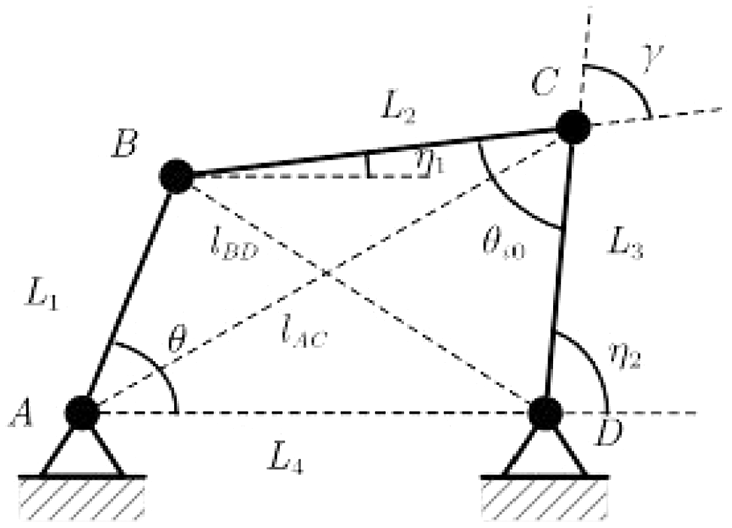
Dynamic model of the compliant four-bar mechanism in its initial state.
In the equation, l BD represents the distance between points B and D, θ is the angle between BA and DA, and θ i 0 is the angle between BC and DC. From the diagram, the vector loop of the flapping four-bar actuator can be analyzed based on its vector closure relationship, resulting in the following expressions for the components along the x-axis and y-axis.

In the equation, η1 represents the acute angle between CB and the horizontal line, and η2 represents the acute angle between CD and the horizontal line. The above expressions can be simplified to yield a function solely in terms of θ and η2. The simplified equation is presented below:

Where,

Following these calculations, the solution obtained is as follows:

Similarly, further calculations can be performed to determine the following results.

Where,
Utilizing the pseudo-rigid body model, the flexible rod L3 in the flapping four-bar actuator is analyzed for compliance. The schematic of the compliant flapping rod in the four-bar mechanism is shown in Figure 4.

Schematic diagram of the compliant flapping rod four-bar mechanism.
In a mechanism, a lower potential energy state is often associated with increased stability, as systems tend to seek configurations that minimize energy. This principle is rooted in the mechanics of systems where potential energy influences equilibrium. Specifically, when potential energy is minimized, the system is less likely to experience disturbances that could lead to instability. Therefore, while it is generally observed that stability is enhanced at lower potential energy levels, this relationship warrants further exploration through a specific analysis of the mechanism in question. According to Howell’s analysis of parameter deviations in compliant mechanisms, making the rods flexible results in the following changes to their lengths.

Where, γ= 0.85. Subsequently, as the mechanism moves and reaches an equilibrium state, variable calculations and analyses are conducted on the compliant four-bar mechanism. Figure 4 shows the model after the flexible treatment of the C-end of rod L3 in the flapping four-bar actuator. Based on the geometric relationships among the rods in Figure 4, the following expressions are obtained.


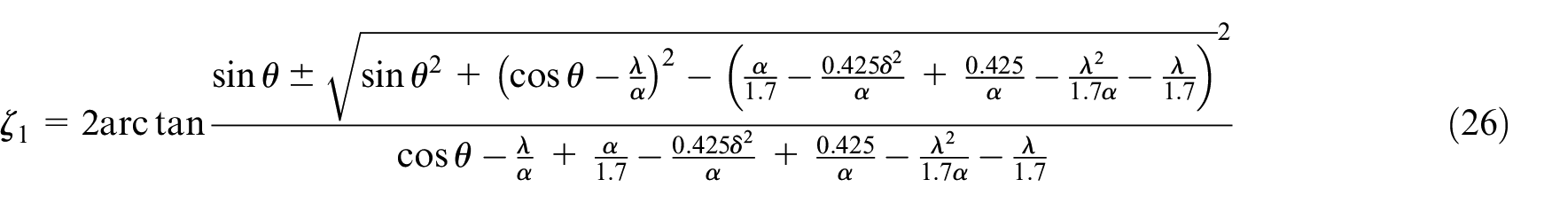
In the equation, ζ1 represents the acute angle between CB and the horizontal line, and ζ2 represents the acute angle between CD and the horizontal line, and θ
i
represents the angle between BC and DC. The deformation


For the pseudo-rigid body model of the flapping four-bar actuator, the potential energy primarily comprises two parts: the first is the elastic potential energy of the springs, and the second is the potential energy of external conservative forces. For displacement loading issues, the external potential energy is zero. The potential energy function of the mechanism is used to solve the minimum potential energy optimization problem. The position of the mechanism corresponding to the minimum potential energy is the equilibrium position under the specified load or displacement. Therefore, the flexible system is more stable at this position. After making the C-end of rod L3 flexible, the potential energy objective function and the vector loop constraint equations for the system are presented as follows.
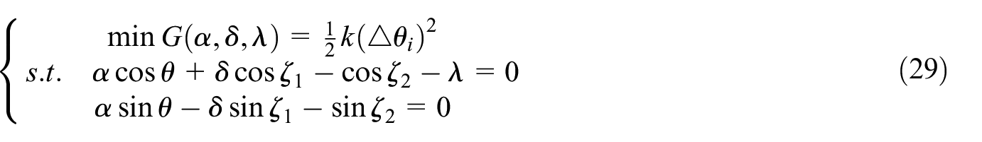
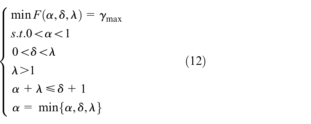
In the equation, G represents the total potential energy of the system, and k is a constant related to the stiffness of the system. Based on the monotonicity of chain functions, the optimization problem for the design of the flapping-wing actuator, considering both geometric and physical relationships, is outlined as follows.

Research methodology overview
This section outlines the methodology employed to optimize the actuator design for the flapping-wing robot. To clarify the overall workflow and the steps involved, a schematic representation of the research process is provided in Figure 5. The diagram illustrates the sequence of actions, from the geometric modeling to the optimization steps, followed by final validation through simulation experiments.

Technical workflow of the optimized actuator design for flapping-wing robots: a multi-objective approach to mimic natural flapping dynamics.
Solving the multi-objective optimization model
Design parameters that closely align with the actual flapping flight process are obtained through multi-objective optimization of the flapping four-bar actuator using the NSGA-II algorithm. Unlike traditional optimization algorithms, NSGA-II incorporates an elitist strategy, utilizes the concept of crowding distance, and features a fast non-dominated sorting approach. This combination not only reduces computational complexity but also effectively prevents the loss of superior solutions during the selection process, ensuring a uniform distribution across the population and maintaining diversity among individuals.
The primary objective of the NSGA-II algorithm in this study is to identify optimal trade-off solutions within the design objective space. Specifically, it seeks to find design parameters that balance minimizing potential energy with achieving the smallest maximum transmission angle, a concept referred to as the “Pareto front.” The process of the NSGA-II algorithm is illustrated in Figure 6, and its fundamental steps are as follows:
(1) Initialize the population: Begin by creating an initial population of potential solutions to represent the parent generation.
(2) Generate offspring: Use fast non-dominated sorting to generate an offspring population through selection, crossover, and mutation processes.
(3) Perform non-dominated sorting: Conduct fast non-dominated sorting on the combined parent and offspring populations, calculating the crowding distance for individuals in each non-dominated layer to assess their relative performance.
(4) Select individuals: Based on non-dominance relationships and crowding distances, select suitable individuals to form the new parent population, ensuring that diverse and high-quality solutions are retained.
(5) Iterate the process: Employ selection, crossover, and mutation on the new parent population to generate a new offspring population. This iterative process continues until the maximum number of iterations is reached.

Flowchart of the NSGA-II algorithm.
The objective of this algorithm is to identify the optimal compromise solutions within the design’s objective space, specifically finding the Pareto optimal set. The fast non-dominated sorting process in the NSGA-II algorithm stratifies the population based on the superiority of individuals, thereby guiding the search direction toward the Pareto front. When seeking the Pareto optimal set, solutions in the population that are not dominated by any other solution form the non-dominated frontier. Dominance in multi-objective optimization involves a condition where one solution is better in at least one objective without being worse in others compared to another solution.
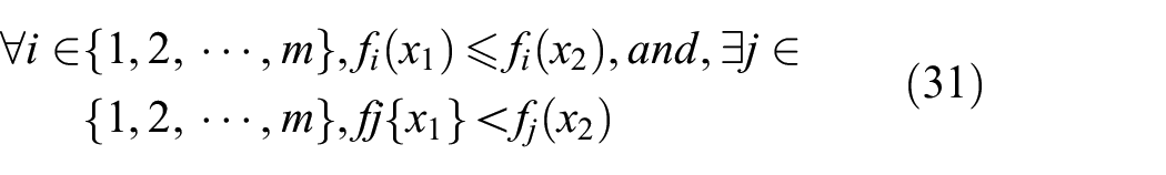
For any given objective component, if the value of x1 is not greater than x2 and there is at least one component where x1 is strictly less than x2, then x1 is said to dominate x2.
The NSGA-II algorithm introduces the concept of crowding distance and a crowding distance comparison operator to address the challenge of maintaining uniform solution sets within the same dominance layer that possess identical fitness values. This innovation eliminates the need for a specified sharing radius in traditional fitness sharing strategies. The crowding distance measure serves as a tie-breaker among individuals at the same non-dominance level following fast non-dominated sorting, ensuring that individuals are well-distributed across the entire Pareto front. This approach helps prevent the loss of superior individuals during the evolutionary process, thereby preserving population diversity.
Crowding distance is denoted by i d , representing the density at a given point in the population. It is defined as the length of a rectangle centered on individual i that includes i but no other individuals, with its vertices determined by the nearest neighbors within the same dominance layer. The calculation process begins by initializing i d , to zero. For each objective, the population undergoes non-dominated sorting. The crowding distances for individuals at the boundaries are set to infinity, while the distances for other individuals are calculated using the following formula:

In the equation, i d represents the crowding distance of point i, f denotes the value of the objective function.
As shown in Figure 7, the clustered Pareto front for the multi-objective optimization visually demonstrates the trade-offs between the two objectives, with each point representing a feasible solution. In the optimization of the compliant flapping rod four-bar mechanism system, the number of iterations is set to 100. The NSGA-II algorithm is employed to conduct multi-objective optimization over specified intervals, aiming to determine the optimal values of α, δ, and λ. The primary objective is to minimize the target function values, which includes achieving the smallest maximum transmission angle and minimizing the potential energy. The results derived from the optimization iteration analysis and computation are as follows:


Pareto front for multi-objective optimization.
Table 2 outlines the configuration of the relevant parameters for the multi-objective optimization algorithm.
Parameter settings for the multi-objective optimization algorithm.

Joint simulation experiments of virtual prototypes
The parameters of the flapping-wing actuator derived from this study are used as the optimized group parameters. Actuator parameters obtained by focusing solely on geometric characteristics through single-objective optimization are designated as the control group parameters. The values for the flapping-wing actuator parameters, optimized based only on geometric characteristics, are presented below.

To illustrate the performance differences between multi-objective optimization designs and those based solely on geometric characteristics, the structure to be simulated is first simplified. This involves distilling the flapping-wing actuator of the robotic flyer down to its essential components, focusing on the key four-bar mechanism that drives the flapping motion. In this simplified model, the crank is replaced with gears, and the wings responsible for the flapping motion are substituted with rockers. A three-dimensional model of the flapping-wing actuator is then created and imported into multibody dynamics software after appropriate data transformations. In this software, the wings undergo flexibility modifications, and various component constraints are applied. Drive conditions are established for the crank, which controls the up-and-down motion of the wings, setting the desired flapping frequency for the flyer. Ultimately, joint simulation experiments are conducted on the rigid-flexible coupled flapping-wing actuator, with the only difference between the optimized and control groups being the actuator parameters derived from different optimization outcomes (Figure 8).

ADAMS 3D model of the flapping-wing actuator.
Figure 9 illustrates the curve of angular velocity for the flapping angle over time for the control group under rigid wing conditions. The graph shows that the angular velocity oscillates within a range of [−1722°/s, 895°/s]. Notably, the slope of the negative angular velocity is steeper than that of the positive angular velocity, indicating that the downward flapping motion of the wing experiences greater negative angular acceleration than the upward motion. This behavior is consistent with the “snap-through” characteristic of spatial crank-linkage mechanisms. However, at the minimum angular velocity, the significant change in slope suggests a rigid impact, leading to high wear rates and a reduced lifespan for the system. To mitigate this issue, the system was modified to incorporate flexibility, and the parameters of the flexible wing actuator derived from multi-objective optimization were analyzed and compared.

Angular velocity curve of the rigid wing flapping angle for the control group.
Figure 10 presents the original scatter data and the fitted curve for the angular velocity of the flapping angle in the control group under flexible wing conditions. The graph indicates that the angular velocity oscillates smoothly within a range of [−715°/s, 950°/s]. Notably, the changes in the slope of angular velocity at the extremes are more gradual than those observed in the rigid wing condition depicted in Figure 9, suggesting a stable motion without rigid impacts. This effectively resolves the issues associated with rigid wings. A further comparison between the angular velocities of the flapping angles in the control group and the optimized group will follow.

Original data and fitted curve of flapping angle angular velocity for the control group’s flexible wing.
Figure 11 presents a close-up comparative view of the flapping angle angular velocities for the optimized and control groups. Figure 11 indicates that the range of angular velocity changes for the control group is [−980°/s, 1250°/s], while for the optimized group it is [−510°/s, 460°/s]. The range of the control group’s flapping angle angular velocity is significantly greater than that of the optimized group, resulting in larger fluctuations. Furthermore, calculations show that the standard deviation of angular velocity for the optimized group is 261.3°/s, compared to 481.0°/s for the control group. Stable flight typically features smaller ranges and standard deviations; excessive fluctuations can lead to unstable flight attitudes. Therefore, the optimized group exhibits better stability.

Comparative close-up view of flapping angle angular velocity before and after optimization.
Figure 12 provides a comparative overview of the transmission angles before and after optimization. It shows that the optimized group exhibits a transmission angle range of 79°–112°, while the control group has a range of 64°–94°. Both ranges satisfy the required transmission angle criteria of 45°–135°. Overall, the optimized group demonstrates a significantly greater variation in transmission angles, with a 10.0% increase compared to the control group. This enhancement facilitates the generation of greater lift and thrust. Specifically, during the ascent phase, the wings of the optimized group are better equipped to capture air and produce increased lift, making this development particularly beneficial for future practical applications that require substantial lift or thrust, such as hovering and vertical take-off and landing in flapping-wing robots.

Comparative close-up view of transmission angle before and after optimization.
Figures 13 and 14 illustrate the displacement curves of the wing center of mass for the control and optimized groups, respectively. Measurements indicate that the endpoint displacement of the wing in the optimized group ranges from 350 mm to 394 mm, while in the control group, it varies from 306 mm to 384 mm. Although the control group demonstrates larger endpoint displacements, the displacement curve for the optimized group exhibits smoother transitions 14 .
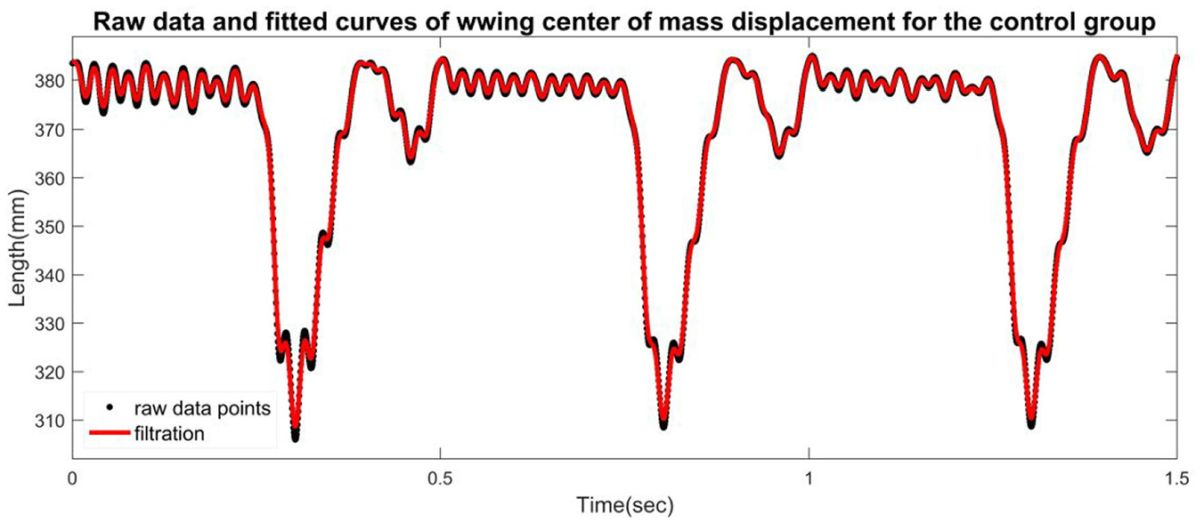
Original data and fitted curve of wing center of mass displacement for the control group.

Displacement curve of wing center of mass for the optimized group.
In the optimized group’s cycle, two distinct increasing and decreasing phases are evident. Notably, at t = 0.162 s, the wings initiate their upward movement, which lasts longer than the subsequent downward motion. This extended upward flapping duration allows for a reduction in acceleration, resulting in decreased power requirements and lower energy consumption, ultimately contributing to a more stable flight for the aircraft. Conversely, at t = 0.659 s, the wings begin their downward motion, which is significantly shorter in duration compared to the upward movement. The increased flapping acceleration during this phase enables a quicker descent, effectively shortening the overall flapping cycle. This reduction in cycle time minimizes air resistance and further lowers energy consumption, enhancing overall flight efficiency. Thus, the optimized design not only improves stability but also promotes more efficient energy use during operation.
Tables 3 and 4 display the frequencies and damping ratios for each mode shape of the optimized and control groups, respectively. The calculations reveal notable improvements in the damping ratios for the optimized group, which increased by 13.3% in the first mode shape, 13.8% in the second mode shape, and 16.4% in the third mode shape compared to the control group. These increases in damping ratios across various modes contribute to a reduction in the system’s overshoot and oscillation frequency, ultimately enhancing the stability of the flapping four-bar mechanism.
Frequencies corresponding to each mode shape order for the optimized group.

Frequencies corresponding to each mode shape order for the control group.

Figures 15 and 16 illustrate the mode shapes of the flapping four-bar mechanisms for the optimized and control groups, respectively. Each figure includes legends indicating the maximum and minimum deformations for each mode shape. In Figure 15, the maximum deformation across all mode shapes is 0.77 mm, whereas in Figure 16, it reaches 0.88 mm, with deformation trends showing a tendency to increase toward the connection points of the linkages. These findings demonstrate that the deformations remain within the permissible limits of the materials used, thus aligning with the design requirements of the flapping-wing mechanisms (Table 5). 15
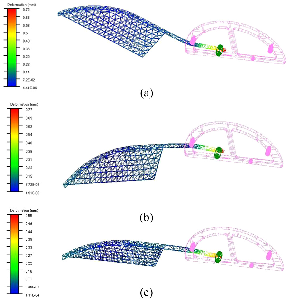
Mode shapes of the optimized group of flap four-bar mechanism in each order: (a) first mode shape of the flapping four-bar mechanism, (b) second mode shape of the flapping four-bar mechanism, and (c) third mode shape of the flapping four-bar mechanism.

Mode shapes of the flapping four-bar mechanism for the optimized group: (a) first mode shape of the flapping four-bar mechanism, (b) second mode shape of the flapping four-bar mechanism, and (c) third mode shape of the flapping four-bar mechanism.
Comparison of flapping mechanism parameters between the initial group and optimized group.
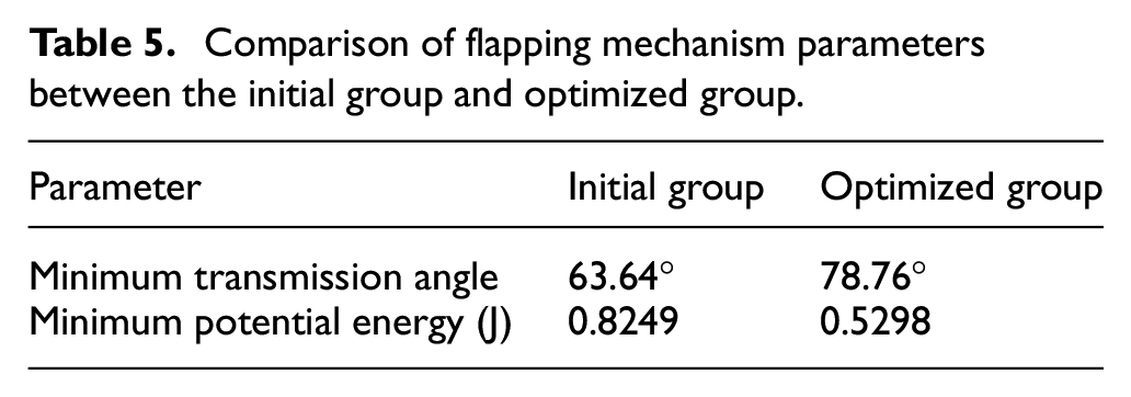
Although the maximum transmission angle in the optimized group 78.76° is larger than that in the control group 63.64°, a significant reduction in the minimum potential energy is observed, from 0.8249 J in the initial group to 0.5298 J in the optimized group. This indicates that, while the transmission angle has increased, the energy consumption has been effectively minimized, which improves the overall system efficiency. The increase in maximum transmission angle, while potentially affecting certain aspects of performance, does not lead to instability or significant detrimental effects on the system’s operation. Therefore, the optimization is considered successful in enhancing the system’s efficiency, with a notable improvement in energy utilization, which is a critical objective for practical applications. 16
Conclusion
This study presents a novel optimization methodology for the actuator of a flapping-wing robot, which integrates both geometric and physical characteristics, overcoming the limitations of traditional rigid system analysis. By reconfiguring the actuator into a linkage mechanism and utilizing the pseudo-rigid-body model to derive accurate mechanical equations, the behavior during flight was simulated more realistically. The proposed multi-objective optimization model aimed to maximize the transmission angle while minimizing the potential energy of the flapping motion. The optimization problem was solved using the NSGA-II algorithm, resulting in significant improvements in the actuator’s performance.
The optimized system, evaluated at a flapping frequency of 4.5 Hz, exhibited a 35.8% reduction in minimum potential energy, a 45.7% decrease in the standard deviation of angular velocity, and a 10.0% increase in the range of transmission angle variation compared to the baseline design, which was based solely on geometric optimization. These results clearly demonstrate the advantages of the multi-objective optimization approach, leading to a more stable, efficient, and realistic flapping-wing actuator that closely mimics the dynamics of natural flight.
In addition to improving actuator performance, this research highlights the importance of integrating both geometric and physical considerations in the design of flapping-wing robots. The validation of the optimization process was carried out through a comprehensive simulation framework involving rigid-flexible coupled virtual prototypes, which provided insights into the actuator’s dynamic behavior and its performance under real-world flight conditions. The findings indicate that the optimized actuator not only enhances flight stability and energy efficiency but also provides better flight control by reducing undesirable fluctuations and improving the lift-thrust generation capabilities.
This work provides a solid foundation for future research on the development of efficient, bio-inspired actuators for flapping-wing robots. The proposed multi-objective optimization framework opens several avenues for further exploration. Future studies could explore the use of advanced materials with enhanced flexibility and strength to improve the actuator’s performance under varying flight conditions. Additionally, incorporating adaptive control algorithms that dynamically adjust to different flight phases could further enhance the stability and efficiency of the system, offering significant benefits for practical applications such as autonomous flight in complex environments. Moreover, further optimization could consider other performance criteria such as noise reduction, durability under long-term use, and responsiveness to external disturbances, contributing to the development of more robust and versatile flapping-wing robots.
In conclusion, the multi-objective optimization approach presented in this study represents a significant step forward in the design of flapping-wing robots, offering both theoretical insights and practical improvements in actuator performance. The successful integration of geometric and physical design principles sets the stage for future advancements in the field of bio-inspired robotics, with the potential to revolutionize the development of autonomous aerial systems.
Footnotes
Handling Editor: Divyam Semwal
Funding
The author(s) received no financial support for the research, authorship, and/or publication of this article.
Conflicting interests
The author(s) declared no potential conflicts of interest with respect to the research, authorship, and/or publication of this article.