
Abstract
The stroke control of a hydrostatic transmission (HST) has an important role for heavy-duty, on-highway, and off-road vehicles like agricultural and construction equipments along with mining and forestry vehicles to increase energy efficiency and power variability. The author proposes a multiple Model Predictive Controller (MPC) and multiple Model Reference Adaptive Control (MRAC) as a new control strategy for stroke control of HST, and compare their performances. The proposed controllers are based on a linear HST system mathematical model to track complex stroke reference trajectories of primary and secondary regulations under the realistic disturbances such as engine and load torques as a result of type of soil and field road conditions. The results of the Processor in the Loop simulations are encouraging in terms of the MPC having advantages over the MRAC and classical control strategies like being able to be designed for multi-input-multi-output systems, insensitive to external stochastic disturbances such as white noise as well as modeling errors and uncertainties to be implemented on an HST for real-time implementation.
Keywords
Introduction
A hydrostatic transmission (HST) can be defined as a ‘pump-controlled motor’. 1 It has a shaft as mechanical input, one or more shafts as mechanical output, and along with a number of internal volumetric machines like a hydraulic pump driven by an engine and one or more hydraulic motors driven by oil discharged pump.2,3 The hydraulic pump converts the input mechanical energy into pressurized fluid and the motor(s) convert(s) it back to mechanical energy to drive the vehicle. 4 Meanwhile, the energy is transmitted from the pump to the motor by oil through flexible lines or hydraulic hoses. HST can operate at the maximum pressure rating of high-performance pumps with the help of these lines or hoses. 5 HSTs are classified into two categories: the ones with fixed displacement pumps and motors; and the other ones with variable displacement pumps and/or motors. 6 HST transmits power from the prime mover to the load like a gearbox in case of having fixed displacement pumps and motors. However, it can regulate power in case of having variable displacement pumps and/or motors. 7 Even though HST has lower efficiency comparing with stepped transmissions; insuring uninterrupted power to wheels during shifting, improved maneuverability, and dynamic braking; operating over a wide range of torque/speed ratios; delivering an infinitely variable or stepless output speed from a constant input speed and a constant speed from a variable input speed such that achieving the vehicle’s stepless speed regulation; producing a maximum torque output from a minimum power input; transmitting high power with low inertia; remaining stalled and undamaged or overheated under full load; and providing flexible equipment layout in design of a vehicle or a machine due to the connection of the pump and motor with flexible hoses are amongst the most important advantages of it.3,5
HSTs have been widely used in heavy-duty, on-highway, and off-road vehicles like agricultural and construction equipments along with mining and forestry vehicles to increase energy efficiency and power variability for more than half a century.1,8–10 They have a very large usage area like tractor,11,12 forklift, 13 excavator, 14 gas turbine, 15 ATV, 16 hydraulic elevator system, 17 robotic systems,18–22 wind turbine.9,23
Linear quadratic gaussian algorithms based on a linear state-space model of an HST for the velocity regulator design of hydrostatic transmissions were suggested. 24 A velocity tracking controller for HSTs was designed utilizing gain scheduled full state feedback was designed. 25 Linear Quadratic Regulator (LQR) is designed based on the linear state-space model of the secondary-regulation HST system. 26 A sliding-mode approach with disturbance compensation by a nonlinear reduced-order disturbance observer for the tracking control of a hydrostatic drive train was proposed. 27 Then they proposed a backstepping second-order sliding mode control approach for the tracking control of the motor angular velocity of the HST. 28 Comparison of the performances of a new type of self-tuning fuzzy PID (Proportional Integral Derivative) controller and classical PID controller for speed control of the HST system was presented. 29 A trajectory tracking control application of motor angular velocity and pressure difference using Lyapunov techniques in combination with a disturbance observer for a drive chain with HST was presented. 30 The generalized control law for the HST ratio for a hybrid driveline including kinetic energy storage with constant pressure system was investigated. 31 The performance of a gain scheduled LQR with feedforward control and disturbance compensation applied to a wind turbine with HST were investigated. 32 A hydrostatic variable-ratio system of a wind power turbine drive train to produce constant electric power at varying wind speeds by controlling the variable displacement hydraulic pump was presented. 33
The importance of usage of MPC has been grown up in on-line applications with the help of modern computers. The design formulation to have a completely multivariable framework with hard and soft constraints, and overcoming the problems of model uncertainties and external disturbances are amongst the most important advantages of MPC. 34 It has been preferred in the usage of various agricultural 35 and automotive36–38 applications. Two MPCs based on linear state-space model of propulsion system were implemented on a New Holland combine harvester to develop a cruise control system by controlling engine speed and the pump setting. The first one minimizes the speed error and the control effort, in addition to them, another one minimizes the engine speed. 39 Gradient and Newton-Raphson-based fast nonlinear model predictive controllers are investigated and compared both for the tracking of the HST’s motor angular velocity. 40 Two distributed nonlinear model predictive controllers were designed in order to track the speed of the hydromotors of the HST and their performances were compared with PID. 41 A nonlinear model predictive controller for the energy management of nonhybrid HSTs in terms of the velocity-tracking and fuel economy was designed. 42 The design and evaluation of the linear MPC method were designed to track engine speed, engine torque, accumulator pressure, and vehicle speed; and compared with the PID-based system under two typical driving cycles in a hydraulic hybrid powertrain system.43,44 An MPC to track a desired hydraulic motor speed while constraining efficient engine operation by regulating the throttle command, pump displacement, and valve opening was devised. 45 A predictive neural network controller was applied to control the rotational speed of the hydraulic engine of HST. 46
In this study, a multiple MPC consisting of two linear MPCs based on linear HST system mathematical model 10 was designed as a new control strategy for stroke control of HST on the strength of the advantages of MPC. Also, a Multiple Model Reference Adaptive Controller (MRAC) was proposed in order to compare the performance of both controllers. The performance of the controllers applied to the nonlinear HST model was tested under the deterministic and stochastic disturbances like engine and load torques as a result of the type of soil and field road conditions and a complex reference trajectory being the combination of both ramp and step functions in order to obtain the system response in primary and secondary regulations of both normal and optimal drive modes. 47 Processor in the Loop (PIL) simulations were carried out in order to handle computational errors and communication delays during the simulations. The results of the simulations are encouraging in terms of the MPCs to be implemented on an HST for real-time implementation.
Mathematical modeling of hydrostatic transmission
There are lots of studies about the modeling of HST in the literature.4,8,10,30,48–51 Among them, the mathematical model describing the dynamics of an HST with variable displacement pump and motor 10 is used on the advantages of MPC design.
According to the HST system in Figure 1, the relations about engine, hydraulic pump, hydraulic motor, and hose must be given. The rotation of the engine and the pump can be described as follows:


Block diagram of the HST system.
where


where

where


where

where


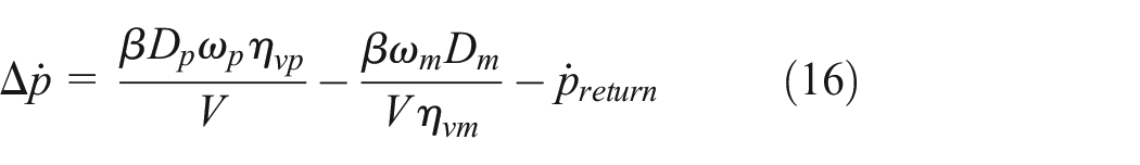
where
There are three system variables to define the dynamic behavior of the system. Therefore the state equations of the system can be summarized by means of the equations (4), (8), (13) as follows:


The nonlinear state space model of the HST can be obtained based on equations (14)–(16). It consists of three first order nonlinear differential equations in state space form as shown below.

where

Model predictive control
MPC comprises an optimization problem that is solved by the quadratic programming method. The MPC control action with the estimates of
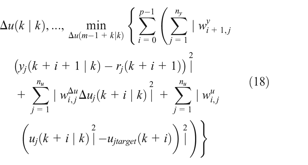
subject to:


In equation (18); .‘

MPC optimizes its control decisions based on future predictions of system behavior. These predictions rely on accurate state estimations, which are provided by the state observer.
State observer
A state observer is used for reducing the prediction error by updating the plant model states

where ‘(

where

where ‘
The role of the state observer is critical for ensuring that MPC receives reliable state estimations. Without the observer, MPC would rely solely on noisy and possibly incomplete sensor measurements, leading to inaccurate predictions and suboptimal control actions. The observer compensates for these uncertainties by reducing the impact of sensor inaccuracies, estimating the effect of disturbances that are not directly observable, ensuring a more robust and stable control response providing refined state estimates for better future trajectory calculations.
In order to implement the MPC and state observer algorithms, the following steps are followed:
State estimation: The state observer, based on Kalman filtering techniques, estimates the system states at each sampling instant using the measurement updates and disturbance models, which were given in equations (23) and (24). In this manner, it ensures that MPC receives accurate state estimations, leading to more effective control actions.
Prediction model update: The estimated states are used to update the prediction model given in equation (19), ensuring accurate future trajectory estimation.
MPC optimization: Using the updated states, the MPC optimization problem whose cost function was defined in equation (18) is solved at each sampling instant to determine the optimal control inputs.
Control application: The first element of the computed optimal input sequence is applied to the system, and the process repeats at the next time step.
This structured approach ensures real-time adaptability and robustness of the control scheme.
Multiple model predictive control
Multiple MPC can be used together when there is a set of pre-designed MPC’s based on current operating conditions, measured outputs, references, and disturbances and a need to switch the appropriate MPC. The active controller solves a quadratic program to determine optimal manipulated variables, while inactive controllers perform state estimation to ensure seamless switching. This approach enhances control performance under varying conditions by addressing nonlinearities with linear control techniques. However, it requires one active controller at all times and does not allow runtime updates to custom constraints. Controller design and review must be performed externally before configuration. 52
Model reference adaptive control
The adaptive controller is designed using the Model Reference Adaptive Control (MRAC) strategy, which operates by dynamically adjusting the controller parameters to ensure that the actual plant output closely follows the output of a reference model subjected to the same input.
53
The fundamental block diagram of an MRAC system is illustrated in Figure 2,

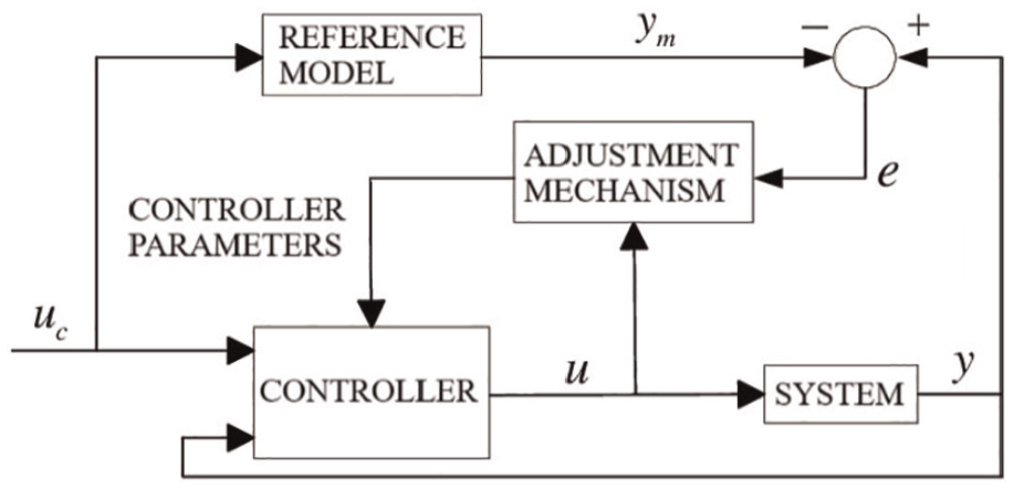
Structure of MRAC 54 .
The MIT rule is widely applicable for designing controllers within an MRAC framework for various systems. According to the MIT rule, a cost function is defined as follows:
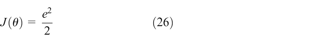
The parameter

The partial derivative term,
Processor-in-the-Loop simulation results and discussion
Linear models were derived from linearizing the nonlinear mathematical model in equation (4) about operating points. Operating points were evaluated by means of defining states with their initial values, inputs with their constraints, and output for both primary and secondary regulations. The states are
Operating points of primary and secondary regulations.
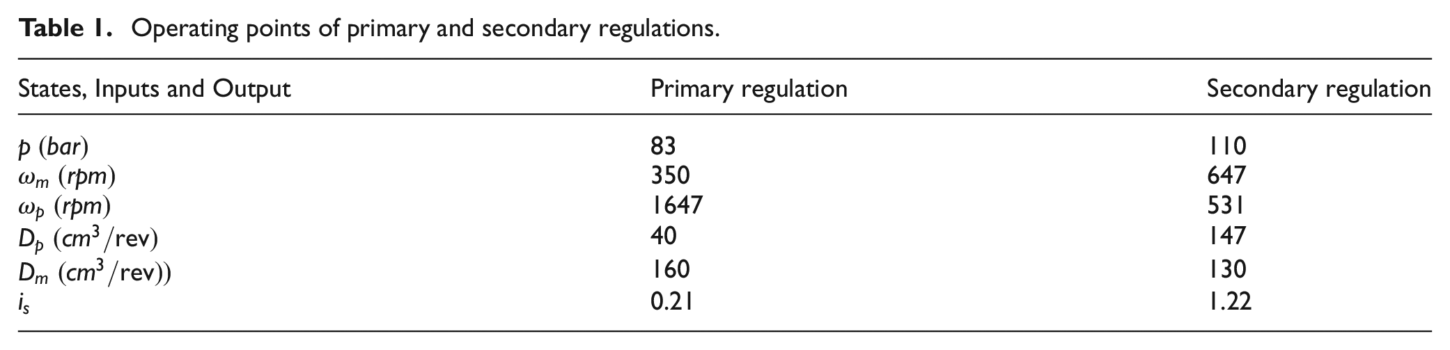
Pump and motor displacements as model inputs are in the region of 0–147 and 68–160 cm3, respectively.
The values of the HST system parameters.

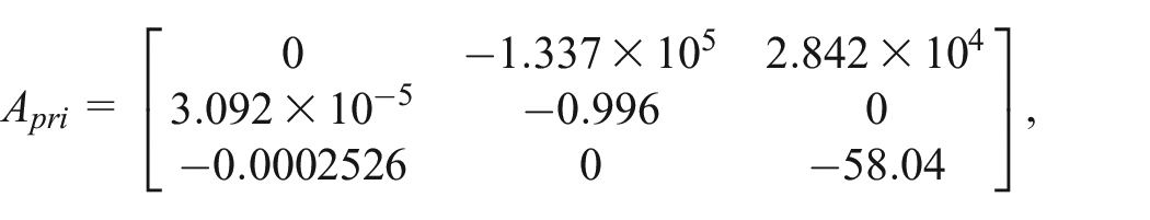
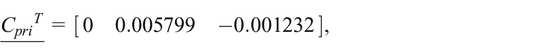
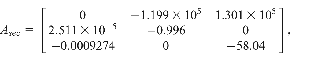
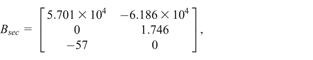
The linear state space models obtained around the operating points above can be seen as follows:

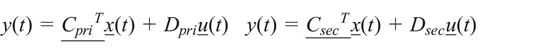
where


The variability of volumetric efficiencies poses challenges, as pump efficiency is defined at a fixed speed (2100 rpm) while typical operation occurs at 1100–1600 rpm, and motor efficiency varies with rotation speed except at high speeds where displacement decreases. To address this, rotational dependency adjustments are made between the pump and motor. Thus, two-dimensional lookup tables with consistent structures for both components were used as detailed in Tables 3 and 4. 10
Volumetric efficiency for the pump. 10

Volumetric efficiency for the motor. 10

As it is known that controllers designed at different operating points by using linear control techniques are switched in solving nonlinear control problems, Multiple MPC Controllers block is used to have a better control of

Block diagram created in MATLAB Simulink of the closed loop system.
Processor-in-the-Loop (PIL) simulation involves using a laptop to simulate the nonlinear plant and a target hardware or processor, where the controllers are deployed, as illustrated in Figure 4. Communication between the two is established via a USB-serial link. The target hardware used in this study is the BeagleBone Black, a cost-effective, compact board equipped with an AM335× ARM Cortex-A8 processor running at 1 GHz, 512 MB DDR3 RAM, 4 GB of on-board eMMC flash storage, and multiple connection interfaces including USB, Ethernet, and HDMI. 55 PIL simulation allows the evaluation of a candidate control algorithm’s performance directly on the target hardware. Unlike standard simulations, it accounts for hardware constraints such as limited memory resources and target-specific code behavior. Through PIL simulation, object code is tested using test vectors developed within a Simulink model, with the code deployed on the actual hardware. This approach enables verification of real code behavior, assessment of code coverage, and measurement of execution time. A key aspect of PIL simulation is that it does not run in real time. Simulink and the deployed object code exchange all input/output data at each sampling period, making communication delays more critical than computation time. Additionally, PIL simulation can help identify deviations in performance caused by the compilation process by comparing the model’s behavior with the deployed object code. 56

Schematic diagram of the hardware used in the PIL simulations. 56
The Multiple MPC was designed in terms of prediction horizon


A Multiple MRAC was designed based on the transfer functions obtained by linear state space models in terms of the output
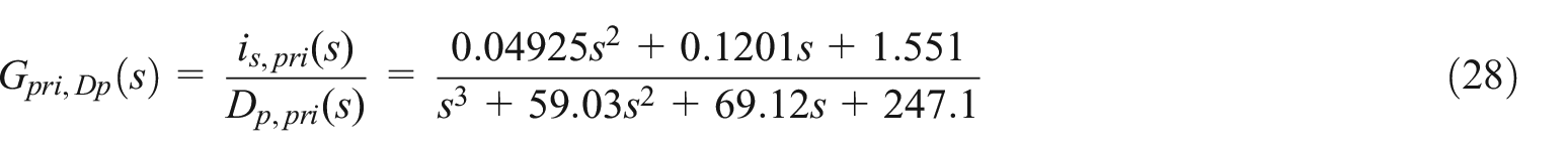


Firstly, an MRAC was designed using equation (28) as follows:


The reference model of the Multiple MRAC was chosen for all inputs and regulations in equation (32).


The control law of the MRAC was chosen as in equation (35).

Substituting equation (35) into equation (32):


Defining

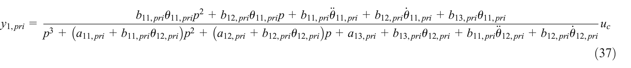
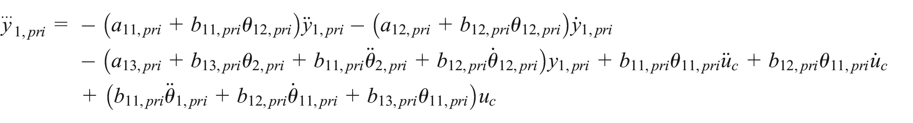
The error can be obtained substituting equation (37) in equation (25).

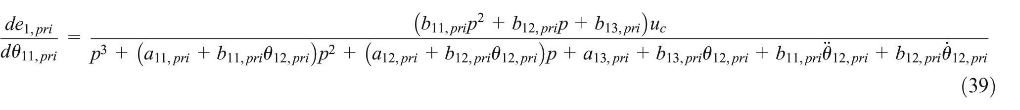
The sensitivity derivatives can be obtained using equations (27) and (38).

The relations between the parameters of the plant and the reference model are obtained equating equations (36) and (34).


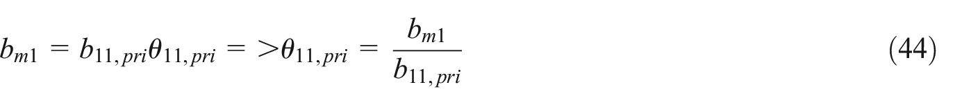


Substituting equation (44) into equation (46):
Substituting equations (41)–(43), (47) into equations (39) and (40):


The Multiple MRAC was designed as shown below by applying the same procedure of the first MRAC design.

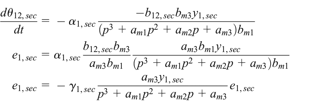


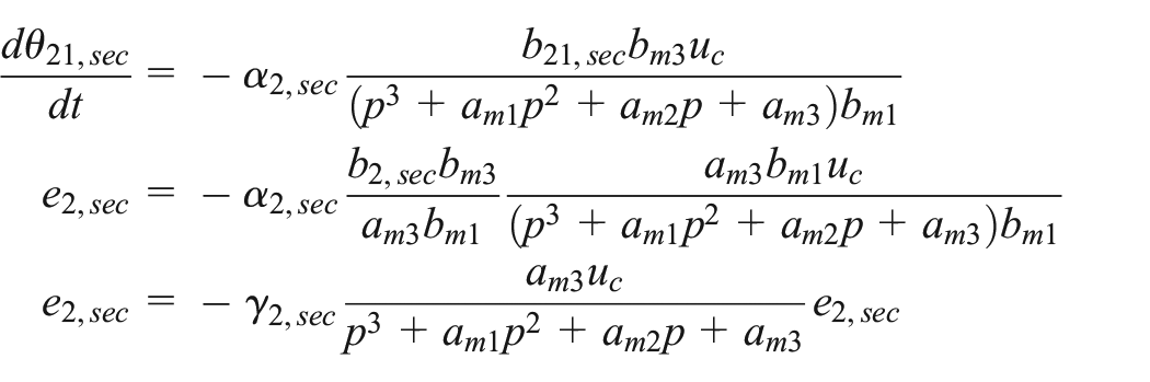

The controller parameters of the Multiple MRAC was chosen as
It is aimed that HST undergoes primary and secondary regulations as mentioned in Introduction section in a desired and controlled manner through constrained multi-input single-output multiple MPC and MRAC. Firstly, the performance of the proposed Multiple MPC and MRAC controllers were tested in case of the complex trajectory and deterministic disturbances.

Stroke responses of the Multiple MPC and MRAC (a) and deterministic torque disturbances (b, c).

Stroke responses of the Multiple MPC and MRAC (a) and volumetric efficiencies of pump and motor (b, c) in case of deterministic torque disturbances.

Stroke response of the Multiple MPC and MRAC (a) and angular speeds of pump and motor (b, c) in case of deterministic torque disturbances.

Normalized percentage of pump and motor displacements of the Multiple MPC (a) and MRAC (b) and switch signal of Multiple MPC and MRAC (c) in case of deterministic torque disturbances.
Finally, the performance of the proposed Multiple MPC and MRAC controllers were tested in case of the same complex trajectory as in the first scenario, but, stochastic disturbances. A uniformly distributed random numbers with a frequency of 1 kHz was used for a interval of

Stroke responses of the Multiple MPC and MRAC (a) and stochastic torque disturbances (b, c).

Stroke responses of the Multiple MPC and MRAC (a) and volumetric efficiencies of pump and motor (b, c) in case of stochastic torque disturbances.
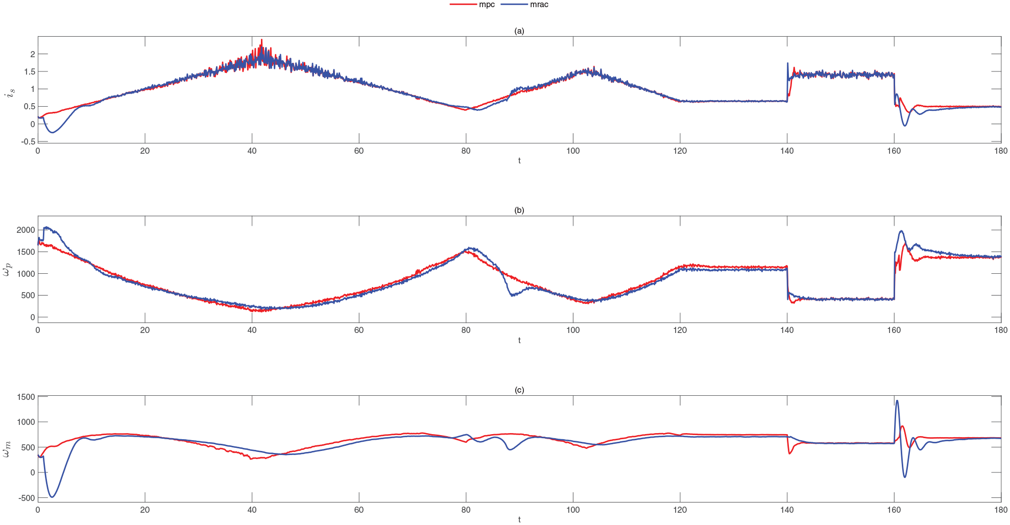
Stroke response of the Multiple MPC and MRAC (a) and angular speeds of pump and motor (b, c) in case of stochastic torque disturbances.

Normalized percentage of pump and motor displacements of the Multiple MPC (a) and MRAC (b) and switch signal of Multiple MPC and MRAC (c) in case of stochastic torque disturbances.
Percentage maximum overshoot (MO), peak time (
Maximum performance measures of the PIL simulations in case of deterministic disturbances.

Maximum performance measures of the PIL simulations in case of stochastic disturbances.

The closed loop system with Multiple MRAC has higher maximum overshoot, peak time, and MSE values compared with the Multiple MPC during the PIL simulations for both deterministic and stochastic disturbances as can be seen in Tables 5 and 6. It can be clearly seen in Figure 5(a) that the proposed Multiple MPC has a superior reference tracking ability and it is insensitive to parameter changes. Due to the change of the volumetric efficiencies and so the angular speeds of the pump and motor in Figures 6(b–c), 7(b–c), 10(b–c), and 11(b–c), maximum overshoots, particularly for the Multiple MRAC, occurred. The proposed controllers to reject the deterministic disturbances in Figure 5(b) and (c) and stochastic disturbances in Figure 9(b) and (c) can be concluded.
Average Effort (AE), Maximum Effort (ME), and Energy Consumption (EC) metrics in terms of controller effort can be obtained from the PIL simulations for both deterministic and stochastic disturbances in Tables 7 and 8.
Controller performances during the PIL simulations in case of deterministic disturbances.

Controller performances during the PIL simulations in case of stochastic disturbances.

It can be seen from Tables 7 and 8 that Multiple MPC exhibits a higher average control effort under both deterministic and stochastic disturbances, indicating a more aggressive control strategy, while Multiple MRAC operates with lower effort, making it potentially advantageous for energy efficiency. The Multiple MPC has higher maximum control effort values, reflecting a more aggressive control approach, while the Multiple MRAC operates with smaller maximum values, which can lead to smoother control. The Multiple MPC consumes significantly more energy in both disturbance conditions, likely due to more frequent and larger control signals, while the Multiple MRAC shows better energy efficiency, consuming less energy overall. As a result, the Multiple MPC provides a faster and more dynamic control strategy, making it suitable for systems requiring rapid response to changes and maintains similar average and maximum control efforts, with a slight increase in energy consumption. So it adapts to new conditions while preserving its aggressive nature.
The whole PIL simulations conducted in this study demonstrate that computational errors and communication delays were not observed, as the control input differences between the model and the object code were consistently zero across all simulations. This confirms that the selection of BeagleBone Black Rev C as the target hardware was appropriate.
It is concluded in the result of PIL simulations that
Conclusions
The stroke control of an HST has an important role in speed control for the whole system of an offroad vehicle such as a forest vehicle or a tractor since it provides to track reference trajectories of primary and secondary regulation for both normal and optimal drive modes. The difficulties of stroke control are based on different disturbances, that is, on a tractor such as type of soil and field road conditions. Classical controllers available in the literature can not provide satisfactory control performance since they are sensitive to these disturbances. In this study, a multiple MPC and MRAC were proposed as a new control strategy for stroke control of the HST, and their performances were compared. Therefore, it made possible to deal with unmeasured disturbances like engine and load torques with the help of the simulation studies. PIL simulations play a crucial role not only in testing and verifying the controller object code but also in evaluating the practical implications of controller design. In this study, the BeagleBone Black has proven to be a practical and effective choice for the target hardware. Moreover, the controllers implemented on this hardware are capable of managing multiple reference changes for system states under varying volumetric efficiencies of pump and motor, and both deterministic and stochastic disturbances, offering enhanced flexibility for tracking complex trajectories. In the meantime, the results of the PIL simulations are encouraging in terms of the proposed multiple MPC to be implemented on an HST for real-time application.
As future work, both stroke and engine speed control will be realized by means of MPCs designs in terms of minimizing fuel consumption.