
Abstract
This study investigates the design method of pure rolling gears with circular arc tooth profile in the normal section. The mathematical equations of tooth surfaces are deduced according to the predesigned circular arc tooth profiles as active tooth profiles. The basic design parameters and mathematical model are proposed for meshing simulation and stress analysis. Meshing performances and stress analysis of the design in this study are compared to referenced pure rolling gears with circular arc tooth profile in the transverse section. Results show that the contact ellipses and peak-to-peak level of loaded transmission errors of the design in this study have tiny differences as that in referenced design. The effect of helix angle on the meshing performance and stress analysis is also investigated in this study. It’s worth noting that the bending strength of the gear pair design in this paper can be significantly enhanced when the helix angle is smaller than 15° compared to the referenced design. It is recommended to design the active tooth profile using circular arc tooth profile in the normal section rather than in the transverse section for pure rolling gear drives especially when the helix angle is no more than 25°, comprehensive consideration the contact and bending strength.
Keywords
Introduction
Spur and helical gears, which are key components of cylindrical gear systems applied in parallel shaft transmissions, serve within a wide range of industrial applications. The involute profile serves as a standard reference for gear surfaces due to its numerous advantages, including enhanced transmission stability, the ability to separate center distances, unchanged direction of the normal force and many other beneficial characteristics. Besides, its processing technology is also mature and abundant. 1 However, discontinuous linear functions of transmission errors (TEs) caused by misalignments in gears without micro-geometry modifications will increase vibration and noise and will be prone to the appearance of edge contacts which will decrease the durability and lifetime of gearing.1,2 Besides, the wear as well as heating generated by the relative sliding between tooth flanks can also have serious consequences, such as fracture and burns. Therefore, the sliding ratio should be limited strictly, especially for the innovation of new types of gear drives.3,4
Beyond the design of traditional involute gears, there is a renewed surge in researching unique gear mechanisms, particularly focusing on non-generated gears with new shapes, such as cosine gear, 5 gears with elliptical line of action, 6 sine gear, 7 Logix gear, 8 S-gear,9,10 etc. The primary manufacture procedure of above non-generated gears mainly could be additive manufacturing in which a variety of materials are used.11–14 The single tooth bending fatigue for meshing gears considering multiaxial non-proportional stress states was studied, which could bridge the gap between the available data and the actual loading conditions.15,16 Beyond those types of gears, pure rolling cylindrical gears have been proposed as a kind of non-generated cylindrical gears,17–20 to be used for power transmissions between coplanar shafts transmission and rack and pinion mechanisms. Combined tooth profiles in transverse section based on several control points was also introduced to form tooth surfaces. 21 Then, the design of pure rolling curvilinear cylindrical gears with parabolic tooth trace was proposed in Chen et al. 22 However, all the aforementioned pure rolling gears are designed based on the tooth profile in transverse section. The tooth thickness changes as the variation of helix angle, and it will be too thin to resist fracture when the value of helix angle is too large. This problem impacts not only the uniform design of gear cutting tools, but also the strength design.
The design method of pure rolling gear drive with circular arc tooth profiles in the normal section is proposed. Mathematical equations of the tooth surfaces are deduced based on the predesigned tooth profiles in the normal section. Then, design parameters and mathematical model are established. Meshing performances including the contact patterns, stress analysis and the function of loaded transmission errors (LTEs) are compared to the referenced pure rolling gears with circular arc tooth profile in transverse section with the same design parameters, considering different values of helix angle.
Applied coordinate systems
Figure 1 shows the coordinate systems, and the meshing line and contact curves are indicated in the red and blue color, respectively. Coordinate systems

Applied coordinate systems.
Different kinds of meshing line functions can be chosen to form the shape of teeth, such as a parabolic function, a circular arc function, a hyperbolic function, among many others.
22
The law of motion of the meshing point
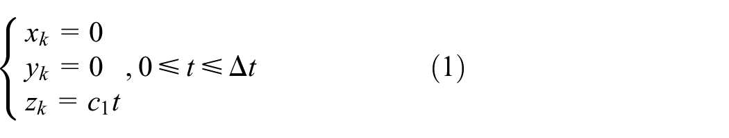
where
The relationship between the rotation angle of the pinion and
Left active tooth profiles in the normal section of pure rolling gears are shown in Figure 2, which also shows the relationship between the normal section and the transverse section. Coordinate systems

Active tooth profiles described in normal section.
Coordinate transformation matrix between

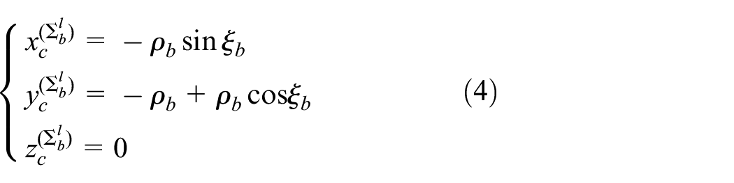
Equations of circular arc

where
Similarly, the equations of circular arc
where
Both the right and left side of the active tooth surfaces can be formed by the normal active tooth profiles moving along the contact curves C1 and C2 shown in Figure 3, respectively, according to Chen et al.19–22 The position vectors of every point on surfaces of gears are determined by:


where:


Sketch of the entire transverse tooth profile.
Design of entire transverse tooth profiles
In order to form the entire tooth profiles, the transverse entire tooth profiles will be deduced. The entire transverse tooth profiles consist of active tooth profiles and transit fillets, which smoothly connect each other at the points
By setting the coordinates
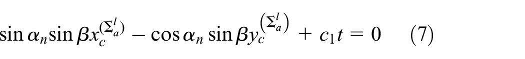

According to equations (7) and (8), the relationship between the angular parameters


Points


Besides, the value of the angle


The fillet curves


where
Design parameters and mathematical model
The pure rolling gears which have circular arc tooth profile in the transverse section are denoted as Type T, while pure rolling gears have circular arc tooth profile in the normal section are denoted as Type N. Design parameters for Type T and Type N are proposed for analysis of meshing characteristics including contact patterns, stress analysis and function of LTEs.
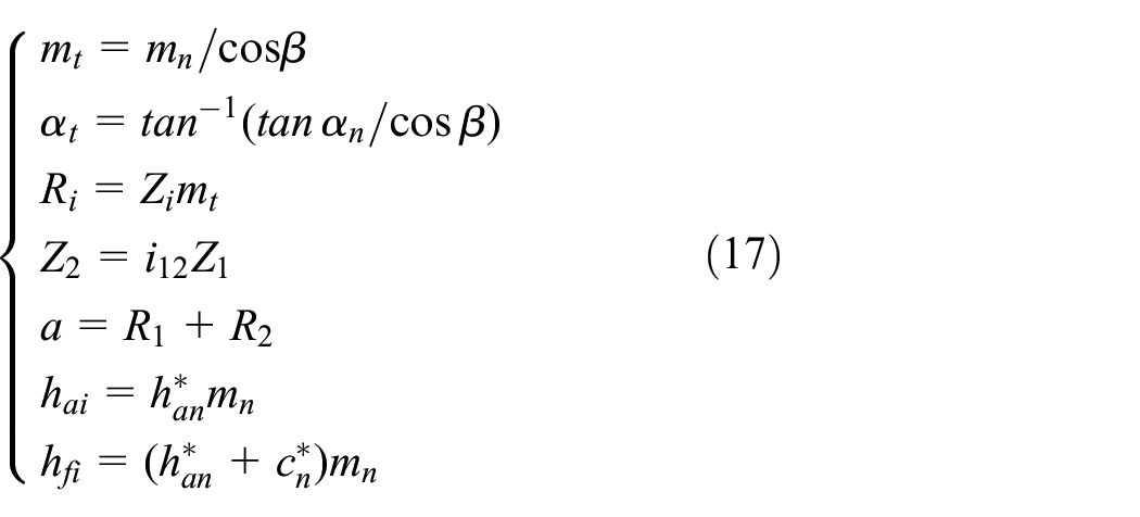
The mathematical expressions of the main geometric parameters are expressed as:
The value scope of the motion parameter

The angles

where
Angles

Besides, the contact ratio

The effect of helix angle on the meshing performance and stress analysis is investigated in this study under the same basic design parameters, as listed in Table 1. Case 1 to Case 8 indicates the helix angle from 10° to 45° for both Type T and Type N, respectively.
Basic design parameters for Type T and Type N.

Figure 4 shows one 3D model of a pair of pure rolling gears of Type N with helix angle 25°, based on design parameters listed in Table 1.
3D model of pure rolling gears of Type N with helix angle 25°.
The comparison of the active tooth surface and fillet surface between gear pair of Type T and Type N with helix angle 25° are shown in Figure 5 which demonstrates the comparison of the active tooth surfaces between Type T and Type N and the comparison of fillet surface between Type T and Type N, respectively. The maximum surface-surface distance between two surfaces of Figure 5(a) is 10.1

Comparison of pinion tooth surface of Type T and Type N: (a) comparison of active tooth surface, (b) comparison of fillet area.
Tooth contact analysis of Type T and Type N
A tooth contact analysis (TCA) algorithm proposed by Sheveleva et al.,
24
was performed to simulate the contact patterns and the functions of TE and LTEs. In order to eliminate the edge contact on the right and left transverse ends of the teeth and to get a parabolic function of unloaded TEs, lead micro-geometry modifications are applied to tooth surfaces of the pinion. The type of lead modification for all 16 cases of design is a parabolic crowning, and the amount is equal to 8

Contact patterns of the pinion with helix angle 25°.

Contact patterns of the gear with helix angle 25°.
As expected, all contact ellipses of the pinion increase from two ends of the teeth to the center with the same included angle between the axis of ellipses and the pitch line. The biggest ellipse covers only part of the middle of the tooth flank. Besides, all the centers of ellipses line on the pinch of the surface. Therefore, the edge contact will be avoided successfully for both top of tooth flank and two ends. The same phenomena can be found on the gear surface. Besides, the direction of the included angle is opposite for the pinion and the gear. Therefore, the idea of pure rolling meshing for both Type T and Type N is realized as they are active designed.
Functions of unloaded TE follow a parabolic function because of the micro-geometry modification a lead crowing applied on the pinion surfaces for all cases of Type T and Type N. The LTEs will be compared after the stress analysis of Type T and Type N under different helix angles are finished.
Stress analysis of Type T and Type N
Finite element analysis has been carried out in ABAQUS 25 based on results of TCA analysis. To eliminate the influence of boundary conditions on both contact and bending stress analysis results, five teeth models of gear pair were generated for both Type T and Type N. The whole simulation was uniformly divided into 21 consecutive contact positions. The results of the central tooth were obtained to show the variation tendency of the stresses.
Figure 8 illustrates the mesh division model of Type N with helix angle 25° for finite element analysis. Sixty-five elements are chosen in longitudinal direction for the tooth surfaces, and forty-five elements are chosen along the active tooth profile as well as fifteen elements for the fillet. The element using in this study is Linear 8-node hexahedral elements of C3D8I.
25
The total number of elements is 273,000 with 329,474 nodes. The material of the gear pair was chosen as steel, whose elastic modulus is equal to

FEM model of gear pair with helix angle 25° of Type N.
The variation of the maximum von Mises stresses along 21 contact positions of the pinion for Type T and Type N is shown in Figures 9 and 10, respectively. Case 1 to Case 8 indicates pure rolling gear drives of Type T and Type N with helix angle 10°–45° illustrated in Table 1, respectively. The maximum von Mises stresses of Type T and Type N for different helix angles are compared in Figure 11. For both Type T and Type N, the maximum von Mises stress of the pinon increases as the increment of helix angle, as shown in Figures 9 and 10. While the fluctuation decreases as the increment of helix angle for both Type T and Type N. What’s more, maximum von Mises stresses of all the cases of Type N are higher than that of Type T. Case 8 of Type N has the highest value of von Mises stress and Case 1 of Type T has the lowest value of that. With the increment of helix angle, the maximum von Mises of Type N increases 1.68%, 3.08%, 5.13%, 6.93%, 9.34%, 13.44%, 15.60%, 15.99% compared to Type T, respectively. However, the differences between the maximum von Mises of Type T and Type N is no more than 7% if the helix angle is lower than 25°.

Curves of the maximum von Mises stresses of pinion for Type T.

Curves of the maximum von Mises stresses of pinion for Type N.

Comparison of maximum von Mises stresses with different helix angles.
Figures 12 and 13 show the variation of maximum bending stresses on the pinion fillet of Type T and Type N along the 21 contact positions. The results of the comparison of maximum bending stresses of each case of pinion of Type T and Type N with the change of helix angle are shown in Figure 14. The fluctuation for each type of the maximum bending stress becomes smooth when the helix angle increases. Meanwhile, maximum bending stresses increase firstly and then decrease. What’s more, maximum bending stresses for Type N are lower than that of Type T at each helix angle. Case 3 of Type T has the highest value and Case 8 of Type N has the lowest value of that. With the increment of helix angle, the maximum bending stress of Type N decreases 11.18%, 8.93%, 6.51%, 6.71%, 5.86%, 5.21%, 4.38%, 3.19% compared to Type T, respectively.

Curves of maximum bending stresses for Type T.

Curves of the maximum bending stresses for Type N.

Comparison of maximum bending stresses of the pinion for different helix angles.
The variation curves of maximum bending stresses of the gear of Type T and Type N along 21 contact positions are shown in Figures 15 and 16, respectively. The results of the comparison of maximum bending stresses of each case of gear of Type T and Type N with the change of helix angle are shown in Figure 17. As the same of the pinion, the fluctuation for each type of the maximum bending stress becomes smooth when the helix angle increases. Besides, the maximum bending stresses increase firstly and then decrease, which is also the same as the curves of the pinion. What’s more, maximum bending stresses for Type N are lower than that of Type T at each helix angle, also the same as that of the pinion. For all 16 cases of design, Case 1 of Type N has the lowest value of maximum bending stress while Case 3 of Type T has the highest value of that. With the increment of helix angle, the maximum bending stress of Type N of the gear decreases 12.71%, 10.72%, 8.40%, 8.18%, 6.85%, 6.78%, 5.21%, 4.14% compared to Type T, respectively.

Curves of the maximum bending stresses of the gear for Type T.

Curves of the maximum bending stresses of the gear for Type N.

Comparison of the maximum bending stresses of the gear with different helix angles.
According to Fuentes et al., 26 Figures 18 and 19 show the functions of LTEs of Type T and Type N. All of the functions of LTEs show typical parabolic curve as designed. The parabolic curves of the functions of LTEs will effectively reduce the noise and vibration which are mainly contributed to discontinuous linear functions of transmission errors because of misalignments between gear shafts. Figure 20 indicates the comparison of the maximum amplitudes of all the cases of two types of design. As the increment of helix angle, maximum amplitude shows a fluctuation decline. The maximum amplitude occurs at Case 1 of Type N, and the lowest of that occurs at Case 8 of Type T. As shown in Figure 19, the curve of Type N is a little higher than that of Type T. The difference valves are 0.13, 0.36, 1.41, 0.37, 0.83, 1.26, 0.28 and 0.45 arc sec, respectively.

Functions of LTEs for Type T.

Functions of LTEs for Type N.

Comparison of the maximum amplitude of LTEs for different helix angles.
Conclusions
(1) The results of TCA and functions of LTEs showed tiny differences between Type T and Type N with the same design parameters.
(2) The fillet bending strength for both the pinion and gear of Type N are enhanced compared to that of Type T with the same design parameters.
(3) Type N will have lower contact strength than that of Type T with the same design parameters, especially when the helix angle is larger than 25°.
(4) If the design parameters are the same, Type N rather than Type T is recommended when the helix angle is no more than 25°.