
Abstract
Harmonic gear with double-circular-arc tooth profile has great advantage in the meshing performance. However, only the single cross section meshing or the adjustment of the flexible gear structure is considered to design the conjugate profile in the current research, which leads to the increase of the machining difficulty and is not consistent with the actual working condition of the harmonic gear transmission. Considering the cone deformation of the flexible gear shell, in the direction perpendicular to the axis, the conjugate of the flexible gear teeth is different from that of the rigid gear. Therefore, based on the envelope theory, a double circular arc tooth profile of rigid gear can be designed to achieve multi-section conjugation. Then MATLAB programming is used to simulate the flexible teeth in multi-section. At the same time, according to the assembly simulation, it is shown that the different parts of the flexible gear are engaged with the rigid gear continuously in the meshing process. The results show that on the premise of not adjusting the structure of the gear, this method is more consistent with the actual working condition of the harmonic gear compared with the method of only designing the tooth profile of the middle section conjugate. During the meshing process, there is a double conjugate phenomenon in some regions. By means of parameter adjustment, effective conjugation can be realized in a wider range. When the wave generator cam rotates 67.13°, the tooth profile of the middle section is separated from the rigid gear, and the pairs of meshing teeth are increased and the load capacity is strong. Through the finite element analysis, the dynamic characteristics of the harmonic gear device under normal working conditions are studied, and it is proved that the design parameters of the device can fully meet the strength requirements. A prototype of the double circular arc harmonic gear reducer is manufactured. And by means of assembly and dynamic performance test, the accuracy error of return is 105.2 s. The continuous conjugate meshing with multiple sections can improve the stability and bearing capacity of the transmission and is suitable for actual production and processing. The continuous conjugate meshing with multiple sections can improve the stability and bearing capacity of the transmission, and this is suitable for actual production and processing of rigid gear.
Keywords
Introduction
Harmonic gear transmission mechanism has the advantages of small volume, large speed ratio, high precision and high efficiency, and so on. Meanwhile, harmonic gear transmission mechanism can transfer motion to the closed space, which makes it widely used in many fields, such as robot industry, precision manufacturing, aeronautics and astronautics. 1
In the transmission process, the harmonic gear transmission should consider the influence of flexible gear elastic deformation on the conjugate motion of the two gear, and the conjugate between the gear teeth belongs to the category of space tooth profile motion.2,3 At present, the middle section of the flexible gear is chosen as the main section of the profile design. On this basis, H Xin and colleagues4,5 has studied the rationality of circular arc profile in the application of harmonic gears by numerical method and designed the basic tooth profile of the double circular arc harmonic drive. X Chen et al. 6 designed the double circular arc profile and analyzed the influence of the double-arc parameters on the backlash by finite element method. And in document, 7 according to the deformation relationship before and after flexible gear assembly and the non-elongation condition of the neutral layer curve, Chen Xiaoxia et al. proposed the equal arc length distribution algorithm to determine the position of the teeth on the neutral layer curve of flexible gear under assembly condition and verified the rationality of the method, which provided theoretical knowledge for finding the position of the deformed flexible gear teeth in this article. In order to adjust the gear profile, X Chen 8 simulated the tooth movement of double circular arc harmonic gear and studied the reasonable meshing interval. In view of the conical angle deformation of the flexible gear, J Wang et al. 9 proposed to guarantee the middle section as the main section by adjusting the radial position of each section of the axial direction of the flexible gear, the wall thickness of the flexible gear, and the radius of the neutral layer. D Liu et al. 10 obtained the involute space rigid tooth profile through conjugation of different sections. Therefore, it is very important to combine the motion of multi-section profile teeth to further design the double-arc profile for harmonic gear drive and analyze its meshing characteristics.
Harmonic gear belongs to the research field of planetary transmission mechanism with small tooth difference, so its system and dynamics need to be analyzed and studied. S Mo et al. 11 proposed a new dynamic model for planetary gearing system and analyzed the equivalent meshing error on different types of gear errors in the external and internal meshing lines for planetary gearing system. And experiment was to verify its rationality, which can provide scientific theory evidence for dynamic design and vibration control for precision double-helical star gearing system.
The wave generator affects the radial deformation, the meshing depth, and the coincidence degree and further affects the transmission performance of the whole device. At present, there are different forms of standard elliptic curve, cosine curve, cam roller, double disk type, and others. 1 On the premise that interference does not occur, N Ma 12 made a thorough study on how to obtain a reasonable backlash. X Chen et al. 13 show that compared with other forms of wave generator, the gear clearance of elliptic wave generator is more even, which is conducive to reasonably distributing the load between the teeth. The typical methods to study the meshing theory of harmonic gear transmission include graphic analysis method, kinematics method, isokinetic curve method, envelope method, power series method, 1 and the improved dynamic method, which are represented by H Xin.4,14
In this article, in view of the influence of the spatial deformation of the harmonic gear on the conjugation of different sections of the plane and the increase of the load between the teeth, the axis section of the vertical cup flexible gear, from the top to the bottom of the cup, is divided into three sections, front, middle, and post, and the original curve of the elliptical wave generator is based on the envelope theory of harmonic gear.1,15 The numerical solution of the tooth profile of the rigid gear conjugated with the flexible gear is obtained. By comparing the meshing analysis of three sections, it is found that the selection of front and rear sections for meshing tooth profile design not only improves the design scheme of harmonic gear profile, but also facilitates its actual manufacturing processing, which is of great significance to the application and research of harmonic gear. Besides, the programming method of MATLAB and the simulation diagram of the motion of the flexible gear tooth profile were used to design the outer enveloping tooth profile with the comprehensive consideration of multi-section superposition. In order to verify the rationality of the design, the MATLAB simulation analysis was made to establish the rigid gear assembly diagram of the flexible gear and analyze the meshing process of the flexible gear ring. And a harmonic reducer is manufactured for vibration and noise detection in robotic arm. 16
Basic parameters
The tangent double-arc profile designed in this article is in the form of wave generator input of the original elliptic curve, rigid gear fixation, and flexible gear output. In the process of cam rotation, the wave generator relies on the outer ring of thin-walled bearing to be deformed into corresponding curve as the original wave generator curve. Flexible gear is an outer gear of a thin-walled shell, which is forced to deform when the wave generator is loaded. Rigid gear has more teeth than flexible gear without deformation and meshes with flexible wheels in space. The calculation of parameter i can be obtained from formula (1). 2 The basic tooth profile design parameters are shown in Table 1.
The basic parameters of tooth profile design.

Here

Tooth profile design of flexible gear
Considering the actual working characteristics of harmonic gear drive, the design model has a hypothesis: 2 In the working process of the flexible gear, the shape of the gear teeth remains unchanged, and only the middle of the gear groove would be changed. The tooth profile of the flexible gear adopts the common tangent double-arc profile. Figure 1 is the basic tooth profile of the flexible gear. Table 2 is the representative meaning of the corresponding parameters in Figure 1.
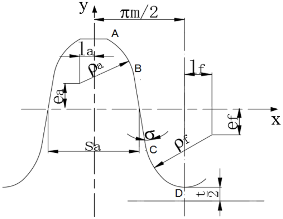
Tooth profile of flexspline.
The basic parameters of flexspline tooth profile.

According to the geometric characteristics of the flexible gear, the parameter equation of the flexible gear can be written in sections. The right tooth profile of flexspline consists of three segments, which are two arc segments and tangent straight line segments. The three segments of tooth profile in flexspline coordinate system are as follows:
Convex tooth profile arc of flexspline (AB segment)

Common tangent of two arcs (BC segment)

Concave tooth profile arc of flexspline (CD segment)

Converting the tooth profile equation of flexible gear into the parametric equation of polar coordinate system


Among these

Here,
Basic parameters of wave generator
According to the processing requirement, elliptical wave generator is adopted at present. In Figure 2, it shows the deformation of the flexible gear with an inner diameter of
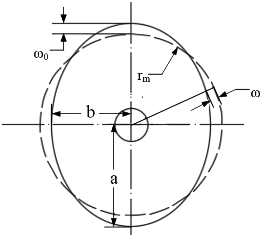
Standard ellipse wave generator.
Primitive curve equation of standard ellipse

Radial displacement

Tangential displacement
Normal rotation angle

Here, a is the radius of the long axis, b is the radius of the short axis, and φ is the polar angle. ρ is the radius of flexible gear related to angle φ, and
Spatial meshing theory of harmonic drive
The harmonic gear transmission belongs to the research category of the planetary transmission mechanism with small tooth number difference, 17 and it also belongs to a space meshing problem of the noncircular gear. 18 There are some important contents, which include studying the spatial meshing theory of the harmonic gear and determining the transformation between spatial coordinate systems of flexible gear and rigid gear during the transmission process, and according to the mathematical parameter equation of the double circular arc flexible gear tooth, the calculation formula of conjugate tooth profile is derived. And reasonable tooth shape parameters are adopted to avoid the overlap interference of the conjugate tooth profiles.
Spatial coordinate relationship between flexible gear and rigid gear
Basic model establishment: as shown in Figure 3. Set up the fixed coordinate system (O-X-Y): the origin O is the center of rotation of elliptic wave generator the Y-axis is reclosing with the long axis of the ellipse, and the X-axis coincides with the short axis direction. Two dynamic coordinate systems (o1-x1-y1) and (o2-x2-y2) respectively represent the reference system where the flexible gear and the rigid gear are located. The y1-axis coincides with the symmetrical axis of the gear tooth, and the y2 coincides with the symmetrical axis of the rigid gear slot. When the wave generator rotates in the direction of Figure 3 at the velocity of
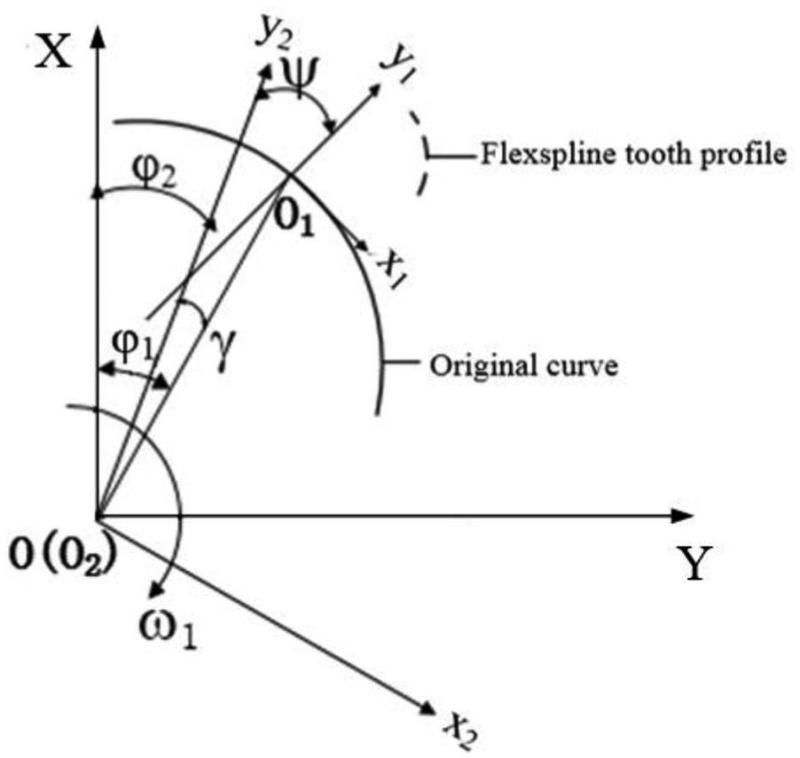
Coordinate position relation between flexible gear and rigid gear.
In the reference coordinate system (o1-x1-y1), the tooth profile equation of the flexible gear is obtained from the above geometric relations, and its parameter form is set as follows
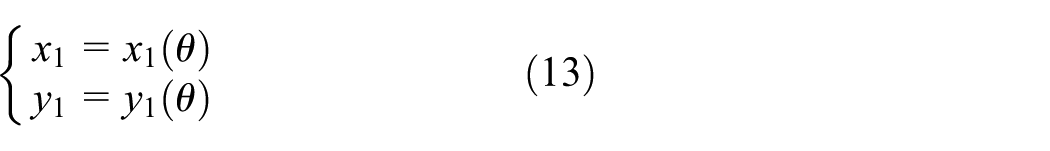
From the flexible gear coordinate system (o1-x1-y1) to the rigid gear coordinate system (o2-x2-y2), the conversion relation is as follows
According to the envelop principle of harmonic drive, 1 the rigid gear profile meshed with the profile of the flexible gear tooth can be obtained

Here,
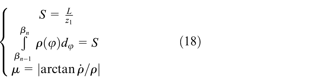
The third formula in formula (7) has partial derivative function, which cannot be solved directly. In general, numerical method is used to lead the flexible gear parameter
Motion path
The key of solving the rigid gear by enveloping algorithm is that after determining the certain points on the flexible gear, a series of corresponding points of the rigid gear coordinate system in the rotation process are obtained after making these points on the flexible gear iterate according to a certain step length. For example, Figure 4 is the motion trajectory simulation of the flexible gear teeth.

Tooth movement track of flexible spline.
The simulation movement is obtained according to the motion law of formula (7) based on MATLAB programming. The middle curve is formed by the middle point of the top of the flexible gear tooth during the motion process, and it is also the motion path of the flexible gear. It can also be seen that the position of the flexible gear in the rigid gear reference system is constantly changing, while the flexible tooth profile has not been changed. If the involute is used as the tooth profile of the flexible gear, it would only form the envelope in the smaller area. For most teeth, there is only the point meshing. As shown in Figure 5, the envelope points of the rigid gear are extracted.

Envelope point on the circular spline.
The design of tooth profile and analysis of meshing
Considering the cone angle deformation of the flexible gear shell, and according to the difference of the main cross section and the different movements of the gear tooth, a design scheme is determined. Then the tangent double circular arc tooth profile can be realized with the teeth of each section of the axial section. Using MATLAB simulation, the design idea is verified, and the motion between the soft gear and the rigid gear is analyzed. And the assembly motion of the two is also simulated to study the meshing condition in the conjugate process.
The design of double circular arc tooth profile
The flexible gear cup body is a thin-walled cylindrical shell structure. In the actual assembly condition, the elliptical wave generator will make the flexible gear taper deformation, which is defined as the front, middle, and rear sections from the cup mouth to the bottom of the cup in the direction perpendicular to the axis of the flexible gear.
9
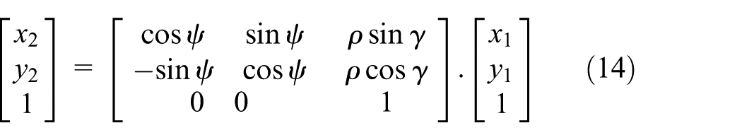
Figure 6 shows the deformation of the flexible gear under the action of the wave generator. Under the deformation of cone angle
Deformation diagram of flexible gear under wave generator assembly.
Assume that the deformation of elliptical semi-long axis under the cone angle

Semi-long axis of ellipse

Here, l is the drum length of flexible gear and
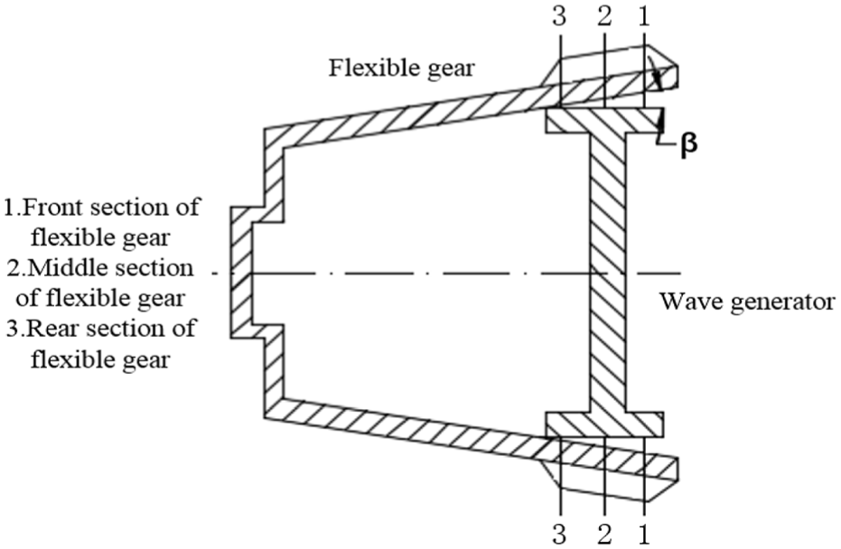
According to the invariance of the elliptical arc length, the parametric equation of each section can be obtained. The three sections of the front, middle, and rear parts of the flexible gear are selected for getting the profile of the rigid gear, and the hash points of the three sections of the conjugate rigid gear are shown in Figure 7. The three curves are obtained according to the envelope principle, so they are theoretically conjugate rigid gear corresponding to sections. However, in the actual design and manufacturing process, it is necessary to ensure as many in-plane flexible gears as possible without interference.

Conjugate tooth profile discrete in three cross sections.
As shown in Figure 7, according to the theoretical meshing gear of the three sections of the front, middle, and rear, the front and rear sections should be designed to make the gear tooth profile in the conjugate state during the rodent process of the rigid gear slot, and the relative theoretical basis is as follows: Through the tooth profile parameters of flexible gear, the rigid gear profile conjugated with convex arc and concave arc of flexible gear could be obtained. Then, the rigid gear arc conjugated with the convex section of the front section of the flexible gear is selected as the root arc of the rigid gear, and the rigid gear arc conjugated with the concave section of the rear section of the flexible gear is selected as the top arc of the rigid gear, so that the flexible gear will always be in the process of the rigid gear groove being meshed into and out of the tooth profile. On the basis of conjugate state, curve fitting and tooth profile optimization are carried out. The hash points in Figure 8 can be selected as the reference profile of the conjugate rigid gear.
The actual design of conjugate gear.
Motion simulation analysis
In order to verify the design ideas mentioned above, and to reflect the movement of harmonic gear in the whole movement, this article uses MATLAB to make programming simulation analysis to determine the movement track of multi-section flexible gear teeth, and also to observe the meshing situation after the assembly of the flexible gear and the rigid gear.
Multi-section motion analysis
Because of the influence of β in Figure 6, the long and short axes of ellipses in three cross sections are different, which affect the motion and meshing of the flexible cross section. The comparison from Figure 9 shows that in terms of teeth height, from the front section to the rear section, the long axis direction of the ellipse decreases successively, and the shape of the flexible gear teeth remains unchanged, but the position of the teeth top decreases successively. At the same time, from the envelope, in order to ensure that the teeth are not interfering under the angle of space, it is necessary to select the envelope of the convex teeth parts of the front section and the envelope of the concave teeth parts of the rear section. The design idea is consistent with that obtained by numerical method above, which proves that it is inaccurate to consider the design and motion of harmonic gears only by choosing the middle section in the past.

Contrast of the movement of flexible gear in three cross sections.
Motion analysis of different cross sections
According to the analysis, it is known that the state of the three cross sections of the flexible gear is different in the case of the wave generator rotating the same angle, so it is necessary to extract the respective meshing state of the meshing completion and the meshing-off stage, which is more convenient to compare and understand the simulation of the whole tooth. In order to facilitate the analysis of the flexible gear motion of different sections, the motion trajectories of three sections are shown in Figure 10.
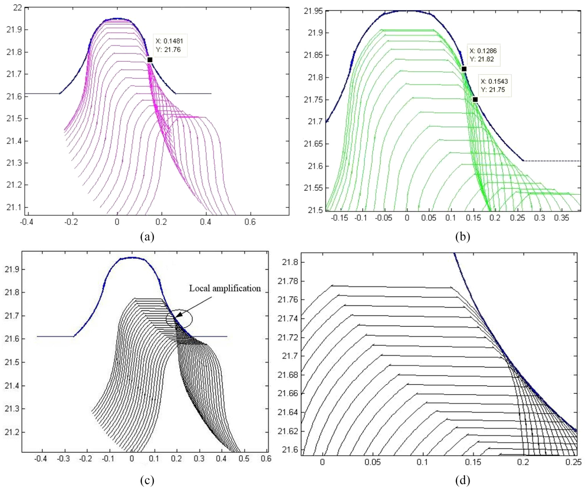
Movement of flexible gear in three cross sections: (a) motion state of the front cross section, (b) motion state of the middle cross section, (c) motion state of the rear cross section, and (d) local amplification of the rear cross section of meshing-off stage.
Under the action of wave generator, there is no teeth profile interference between the flexible gear and the rigid gear. In the process of the 90° rotation of the flexible gear, it is not a conjugate of a single section, but continuously conjugated from the front section to the middle section then to the rear section, and the meshing point is constantly changing. From the range of transverse coordinates, within the range from 0 to 0.1481 of the long axis, the rigid gear is meshing with the front cross section of flexible gear; within the range from 0.1286 to 0.1543 of the long axis, the rigid gear is meshing with the middle section of flexible gear; Bigger than 0.1543 above, the rigid gear is meshing with the rear section of flexible gear. And within the range from 0.1286 to 0.1481, the rigid gear is meshing with both front and middle sections. This conjugate property can be used to achieve a wider range of effective conjugate regions by adjusting the teeth profile parameters. It also proves that the double circular arc teeth profile has the transmission stability and better bearing capacity.
Performance analysis of meshing assembly
In the meshing process of the flexible gear and the rigid gear, the rigid gear is considered as a rigid structure, and its teeth are distributed according to the equiangular distribution of the general circular internal gear. But the flexible gear, as a flexible component, also deforms into an ellipse under the action of an elliptical wave generator. According to Chen Xiaoxia’s theory, the distribution of the flexible gear tooth is arranged according to the length of the arc between the teeth. The hypothesis theory 2 is based on the hypothesis of “the constant tooth shape, the total arc length of the flexible gear,” which is still applicable.
Determination of gear tooth position after deformation
The flexible tooth in the long axis direction of the wave generator is taken as the first tooth. The root position angle of the first tooth is β1 = 0, and the deflection angle of the first tooth relative to the wave generator is
where
Due to the symmetry of the gear ring, a quarter of the teeth is generally selected as the research object. So according to the above equation, the position of the teeth is solved iteratively, and then the assembly of the entire gear ring is obtained by the relationship of symmetric mapping. At the same time, the elliptic parameter equation of different sections is no longer uniform, that is, the position of the flexible gear teeth of different sections is also different. The corresponding teeth positions of the front, middle, and rear three sections of the flexible gear can be obtained by MATLAB programming iteration. Due to the small difference of the location angle, the difference between the front section and the rear section of the teeth root location angle is shown in Figure 11. The order of magnitude is

Different positions of flexible gear in different sections.
Flexible gear has 240 teeth, and Figure 11 shows the different positions of 60 teeth of flexible gear (1/4 teeth of flexible gear). The difference of the deflection angle of the 30th tooth is up to 0.0014 (rad), which is of great significance for studying the meshing of flexible and rigid gear in precision harmonic drive. It can be seen that at the position of the long and short axis, the angle of the root position of the three sections of the flexible gear is basically coincided, indicating that the state of each section is consistent when the flexible gear is fully meshed and completely separated.
Meshing assembly simulation
After iterative calculation based on MATLAB programming, the assembly diagram of the flexible gear rigid gear is obtained, as shown in Figure 12. And the tooth profile of the outer ring is a round rigid tooth profile, and the tooth profile of the inner ring is a flexible tooth profile. From the design process of the gear profile of the rigid gear, it can be seen that, during the engagement and detachment, not a certain section is completely meshed or disengaged, but gradually alternates from the front section to the rear section. In order to show the motion state of the harmonic gear clearer, draw a local magnification of the cross section assembly of the flexible gear and the rigid gear.
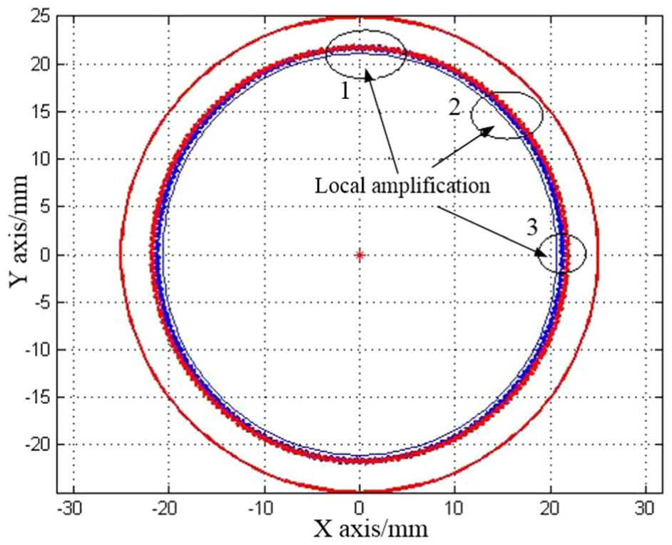
Flexible gear and circular spline are assembled.
Figures 13–15 are enlarged views of 1, 2, and 3 in Figure 12, respectively.

Local enlargement of meshing at long axis.

Local enlargement of meshing in transition stage.

Each section of the flexible gear completely separated.
In Figure 13, it is known that during the assembly of the flexible and rigid gear, the whole gear teeth is in the meshing state in the long axis position, and their teeth have no interference. Under the action of the wave generator, the addendum of the front section of the flexible gear is in meshing with the rigid gear, and the rear section of the gear teeth is disengaged at the same time.
When the whole gear teeth are out of meshing, as in Figure 15, the teeth of the front section of the flexible gear gradually disengage from the meshing state, while the top of the rear section begins to engage with the arc of the rigid gear top in turn, and there is no interference. In the short axis, the teeth of the flexible gear completely detached from the rigid gear, and the engagement movement of the 1/4 arcs ended, and at the same time, it entered the next cycle movement.
The motion model shows that the meshing points are constantly changing from the front section to the middle section, to the rear section, and the quantity of meshing teeth are increased. This engagement and disengagement state are caused by the periodic motion of the cylinder body of the thin wall flexible gear. It also proves that the above design idea is in line with the actual working condition of the harmonic gear device, which shows that the double circular arc harmonic gear drive has the characteristics of stable movement and good bearing capacity.
Meshing backlash laws
Assume that there is a random point K1 (XK1, YK1) on the flexible gear, and the radius is the distance between K1 and the Origin O. From point of origin, do a circular arc with adjacent tooth profile, which is intersect at point K2 (XK2, YK2). And Figure 16 is the K1, K2 model of the meshing side gap.

Tooth profile meshing backlash model.
The backlash between the flexible gear and the rigid gear teeth profile is the distance between K1 and K2, that is, the calculation method is

When calculating the side gap, the minimum side gap is calculated along the tooth height at several points in each meshing position. Experience has shown that the top of the flexible gear tooth can be chosen as K1. 2 Because of the symmetry of harmonic gears, the wave generator varies according to the iteration step of 2 degrees in [0°,90°].The points in the range of 0°∼70° are taken as the main object of calculation. There are 35 K1 points in total, that is to say, the vertex of the tooth rotates 35 times. The distribution of the backlash with reference to the middle section is obtained as shown in Figure 17.

Harmonic drive backlash distribution.
In Figure 17, a series of hash points with obvious distribution rules representing the value of backlash is shown. MATLAB curve fitting toolbox is used for high-order fitting to facilitate observation.
The parameters obtained by MATLAB fitting are: SSE (sum of squares of errors): 7.191e-006, R2 (coefficient of determination): 0.9987, RMSE (root-mean- square error): 0.0005363. It could also be seen in Figure 17 that the fitting effect is good, and the backlash value is basically balanced in the curve, and there is no obvious deviation point.
During the rotation of the wave generator, the backlash of flexible gear and rigid gear increases first and then decreases nonlinearly. The maximum backlash value is 0.03622, when wave generator rotates at 67.13°; the minimum backlash value is 0.00367, occurred at 67.13°. Therefore, it can be considered that when the wave generator rotates more than 67.13°, the teeth of the cross section of the flexible gear are detached from the rigid gear. During the meshing process of harmonic drive, the condition of no overlapping interference on the profile is always satisfied and no overlapping interference on the profile will occur.
Dynamic simulation analysis based on ABAQUS
FEM analysis can be used to analyze dynamic characteristics of the harmonic gear very well. The stress and strain of the whole device would be changed when there is load output at the end of harmonic gear. 19 In order to study the dynamic characteristics of the harmonic gear, the following steps are adopted to simulate the harmonic gear under normal working conditions.
First, when the wave generator is loaded into the flexible gear, a small displacement is given to make the drive part and the follower part contact. Second, only the axial freedom of flexible gear is constrained. And given the radial displacement of 0.3 mm, the motion of flexible gear propped up by wave generator could be simulated. Then the angle of 0.01 rad is given as the initial rotation angle of flexspline. Finally, by given 30N.m load in the software, the motion of harmonic gear is simulated, and the stress and strain of harmonic gear under this load are obtained to analyze.
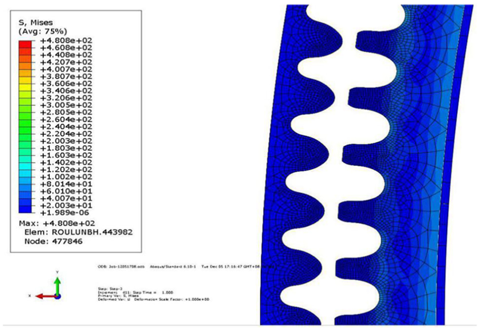
Figure 18 shows the maximum equivalent stress distribution of the flexspline at the long axis. The maximum partial equivalent stress value on flexspline is 480.8 MPa, which appears at the meshing point between the flexspline convex teeth and the rigid concave teeth, far less than the yield strength value of 30CrMnSiNiA used in the flexspline material of 835 MPa. Therefore, the design parameters of the flexible gear can fully meet the strength requirements without plastic deformation. Meanwhile, the stress distributes well in the ring part, the number of meshing teeth is more, the transmission is more stable, and the mechanical properties are superior. Figure 19 shows the stress distribution of the flexspline at the short axis. Obviously, the flexspline is separated from the rigid gear at this time, and the backlash is evenly distributed, which is conducive to form a good oil film.

Mises cloud map at long axis.
Mises cloud map at short axis.
Verification
Based on the above design method, according to the known flexible gear and its parameters, the tooth profile of the rigid gear is obtained and processed, as shown in Figure 20(b). By assembling the known flexible gear with the machined rigid gear, a new double circular arc tooth profile harmonic gear reducer is developed to test and verify the rationality of the method, as shown in Figure 21. Among these, the rigid gear is a small module internal gear, and the material is No. 45 steel. The hardness of the flexible gear is in the range of HRC28-36, and the material is 30CrMnSiA, which is generally used in harmonic reducer. The parts that are processed are shown in Figure 20.
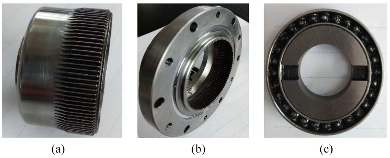
Harmonic gear reducer with double circular arc tooth profile: (a) flexible gear, (b) ring gear, and (c) wave generator.

Assembly of harmonic gear reducer: (a) main view and (b) side view.
Hardware configuration and software module of test bench
Figure 22 is a sketch of the dynamic test platform. The input end of harmonic reducer is driven by servo motor. In order to avoid the excessive speed of the motor, the worm gear reducer is used to speed up the input shaft and the output shaft can be connected with high-speed and low-speed grating angular displacement sensors, respectively, by coupling. The signals picked up by two grating angular displacement sensors are sent to capture card (NI), and the return difference curve of reducer is obtained by computer sampling and data processing.

Schematic diagram of test bench.
The software testing platform of this test is a matching product developed by the company. Based on LabVIEW, the main modules of the software platform are shown in Figure 23, including driving unit parameter input, harmonic reducer basic parameter input, test item selection, data acquisition, and data processing module, which can interact friendly and operate conveniently.

Software testing bench module.
Return difference test results
Compared with the ordinary gear transmission, the harmonic gear transmission can engage with zero backlash, and even achieve high smooth meshing under a certain degree of tightness. Even so, it will not reduce the transmission efficiency of the system. In this experiment, the return distance difference is calculated by changing the torsion direction of the harmonic drive of the prototype. Some measurement points were selected for testing, and the return difference test curve shown in Figure 24 was obtained.
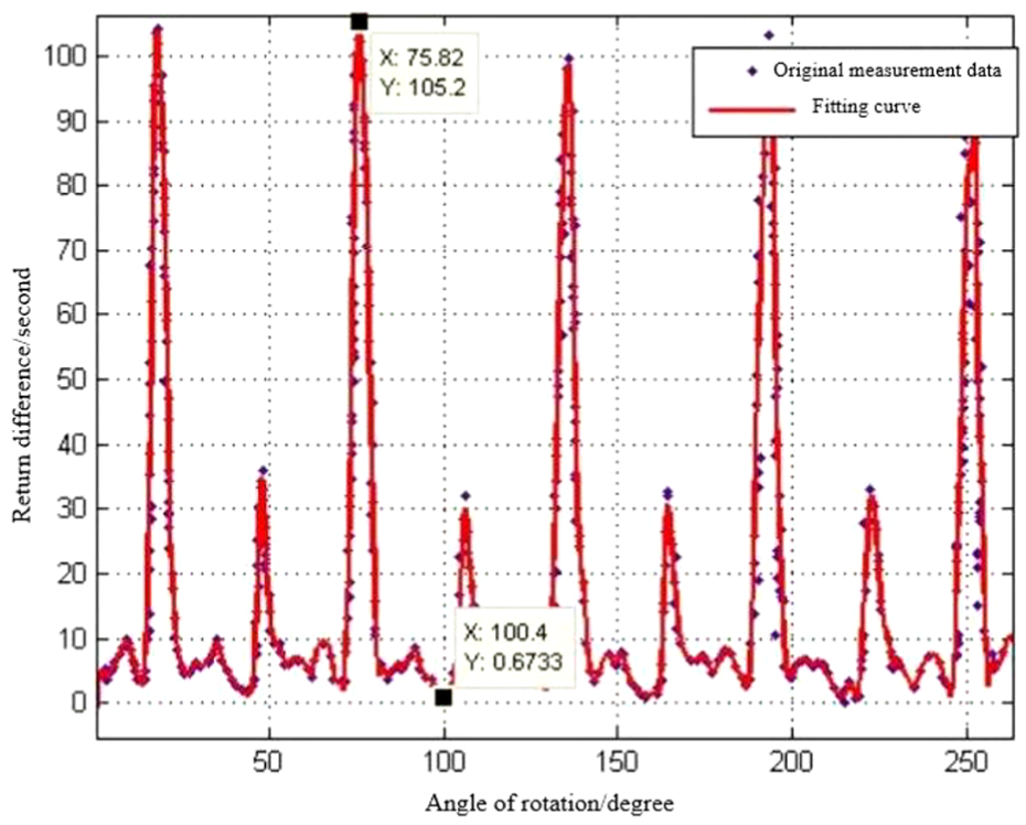
Return difference test curve.
MATLAB curve fitting toolbox “Smoothing Spline” function is used for spline curve fitting. After fitting by MATLAB, the R2 of the curve is 0.9245, and the specify-coefficient of curve smoothness - is 0.975. Also can be seen in Figure 24, the fitting effect is good. And the original measurement data are evenly distributed on the curve, the return error has a certain periodicity, the maximum error is 105.2 s, and the minimum return difference is nearly 0.
Vibration and noise detection
Harmonic gears are applied to the single-degree-of-freedom robotic arm in this test. 15 In order to verify the vibration and noise of the harmonic reducer, the harmonic reducer and the iron plate are assembled, and the belt pulley driven by the conversion motor is used as the power input to simulate the single-degree-of-freedom swing of the robot arm. As shown in Figure 25, the main view and the top view of the swing test platform are assembled. The swing range of the robot arm is 180°, and the speed of the motor can be adjusted to test the noise at different speeds. The results are shown in Table 3.
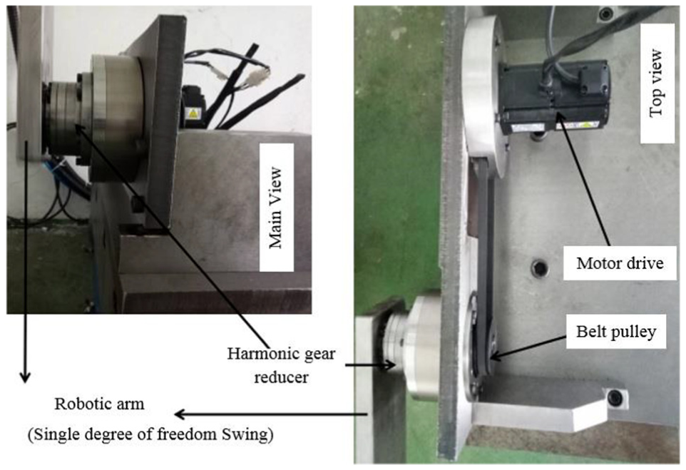
Vibration and noise testing of harmonic reducer.
Noise test of harmonic reducer at different speeds of motor.

Appropriate noise and vibration are acceptable in the environment of industrial robots. Besides, the processing accuracy and material processing technology can be improved appropriately to meet the market demand.
Conclusion
The design of rigid gear of harmonic gear drive directly affects the performance of the whole device. Based on the theory of envelope method, this article presents a method to solve conjugate tooth profile according to multi-section. Based on the known parameters of the flexible gear,the corresponding conjugate profiles with the front and rear sections are selected as the actual profiles of the rigid gear, which does not need to adjust the structure of the flexible gear. The method in this article avoids the inaccurate calculation of rigid gear profile in traditional design, which only considers the meshing characteristics of the middle section.
Footnotes
Handling Editor: James Baldwin
Declaration of conflicting interests
The author(s) declared no potential conflicts of interest with respect to the research, authorship, and/or publication of this article.
Funding
The author(s) disclosed receipt of the following financial support for the research, authorship, and/or publication of this article: The project was supported by National Key Research and Development Program of China (2017YFB1104600) and the Open Fund of the State Key Laboratory of Integrated Optoelectronics (IOSKL2018KF03).