
Abstract
As a critical component of vehicles, automobile drive axle shells are susceptible to issues such as body cracks, half-shaft casing mating surface wear, and axle head thread damage during service. These problems not only degrade vehicle performance but also compromise driving safety. To address these challenges, this paper proposes a systematic approach combining residual life prediction and surface damage remanufacturing. X-ray diffraction technology is used to analyze the stress state of key areas of the drive axle shell, allowing for the prediction of its remaining life and identification of parts suitable for remanufacturing. For different types of damage, this study investigates surfacing, brush plating, and micro-arc deposition technologies to repair cracks, mating surface wear, and thread damage in the axle housing, respectively. The experimental results demonstrate that this approach significantly enhances the quality and reliability of remanufactured drive axle shells. Specifically, the hardness of the overlay repair layer, prepared using ER50-6 wire, reaches HRC6; the grain size of the special nickel-based brush plating layer is approximately 15 nm; and the magnetic memory gradient change in the remanufactured threads, created by micro-arc deposition, is only 3.4 A/(m−1 mm−1). These outcomes satisfy the practical requirements for hardness, wear resistance, residual stress distribution, and thread joint performance. This paper establishes an efficient, precise, and sustainable repair system for automotive drive axle shells by integrating advanced inspection technologies and diverse remanufacturing processes. The proposed system offers novel solutions and technical support for extending the service life of automotive parts and promoting green manufacturing.
Keywords
Introduction
The automobile drive axle housing is a critical component of the vehicle transmission system, accounting for more than 30% of the total axle value. As an essential part of the chassis system, the drive axle housing supports the vehicle’s weight while withstanding road reaction forces and transmitting torque. However, during service, external factors such as rain and mud erosion, alternating stress, unstable random loads, and wear on mating surfaces can lead to structural surface failures, including cracks, wear, and thread damage. 1 These damages weaken the mechanical properties of the drive axle housing, degrade vehicle performance, and jeopardize driving safety.
The primary failure modes in drive axle housings include surface cracks on the axle body, excessive wear on the half-shaft sleeve mating surface, and thread damage to the axle head. Addressing these failures requires a systematic remanufacturing process consisting of three key steps: (1) removing surface contaminants using green cleaning technology; (2) analyzing the stress state and residual life of critical parts using non-destructive testing methods such as X-ray diffraction; (3) restoring the functionality and reliability of key components through surface repair processes such as cladding, brush plating, and micro-arc deposition.
Significant advancements have been made in cleaning technology, non-destructive testing, and remanufacturing processes in recent years. Ultrasonic cavitation thin-film water, quasi-continuous laser cleaning, and plasma shock waves have demonstrated notable effectiveness in removing contaminants and optimizing process parameters (e.g. pulse incidence angle, wavelength).2–7 In non-destructive testing, methods based on convolutional neural networks, finite element analysis, and physical information neural networks (PINNs) have enhanced predictions of stress distribution and residual life.8–13 Surface repair studies reveal that crystal structure control in cladding processes greatly influences corrosion resistance and fatigue life, with ER50-6 wire widely used for its toughness and crack resistance.14–19 Brush electroplating improves substrate bonding strength, wear resistance, and plating uniformity, with nickel base layers significantly enhancing scratch resistance.20–23 Micro-arc deposition offers high precision in localized repair, with proven effectiveness in surface strengthening and stress relief as validated through low-stress and rolling contact wear experiments.24,25
Despite these advances, research on remanufacturing complex hollow steel plate structures like drive axle housings remains limited.26–31 Traditional life prediction methods, such as machine learning-based models and empirical fatigue analysis, often depend on extensive datasets or simplifying assumptions, making them inadequate for addressing complex damage mechanisms. Furthermore, systematic integration of remanufacturing technologies for various damage forms has yet to be achieved. To overcome these limitations, this study proposes a systematic remanufacturing approach that combines residual life prediction with advanced surface repair techniques.
Using X-ray diffraction inspection and bench fatigue testing, this study develops an accurate residual life analysis model for drive axle housings. It integrates cladding, brush plating, and micro-arc deposition technologies to address crack repair, mating surface restoration, and thread remanufacturing. Experimental results demonstrate that the overlay layer prepared with ER50-6 wire achieves a hardness of HRC6, the grain size of the nickel-based brush plating layer is approximately 15 nm, and the maximum variation in the magnetic memory detection gradient of the threads generated by micro-arc deposition is only 3.4 A/(m−1 mm−1), all meeting practical application requirements.
This study provides an innovative and sustainable technological pathway for efficient remanufacturing of automotive drive axle housings, overcoming the limitations of traditional methods. As the world’s largest automobile manufacturing industry, China stands to benefit significantly from combining advanced repair technologies with predictive maintenance. This approach supports green manufacturing and the development of a circular economy, offering substantial application prospects and technological advancement potential.
Methodology
Automotive drive axle housing remanufacturing blanks primarily come from two sources: reworked faulty parts from service and unqualified parts. When repairing failed axle housing components, the process includes paint removal, cleaning, and surface inspection. After non-destructive testing for both quantitative and qualitative analysis, suitable blanks for remanufacturing are selected, while parts that do not meet remanufacturing standards are designated for scrap. The typical structure of the automotive drive axle housing, which involves common steel plate stamping and welding, is shown in Figure 1 below.

Stamped and welded steel plate axle housing structure.
Following the implementation of the remanufacturing process for automotive drive axle shells, a subsequent evaluation is essential to assess the construction quality and reliability of the remanufacturing degree. The specific steps of the remanufacturing process are illustrated in Figure 2 below.

Automotive drive axle housing remanufacturing process flow diagram.
To achieve the remanufacturing of automotive drive axle shells, the process can be carried out in the following steps:
(1) Effective Cleaning: The first step is to ensure thorough cleaning of the automotive drive axle housing, which serves as the foundation for subsequent non-destructive testing and the remanufacturing process. This involves analyzing the contaminants on the faulty parts of the axle housing, selecting appropriate cleaning methods, and determining the components of the cleaning agent to ensure environmentally friendly cleaning.
(2) Identification of Failure Points: After cleaning, the next step is to identify the key areas where failures are most likely to occur. X-ray diffraction inspections are then performed to assess the degree of plastic deformation damage in these critical points by analyzing the residual stress. This data is combined with bench test results of the axle casing to construct a model that predicts the remaining life of the automotive drive axle housing.
(3) Selection of Remanufacturing Blanks: Axle housings with sufficient remaining life are selected as remanufactured blanks, and the failure modes are analyzed. The distribution of various failure modes in returned axle housings, shown in Figure 3, is based on data analysis from an automotive drive axle housing manufacturer.
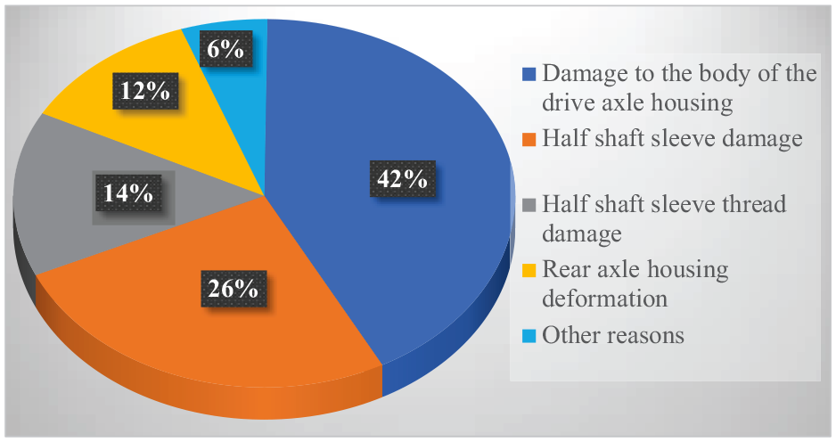
Statistics on the damage failure forms of the axle housing of the returned faulty parts.
The percentages of various failure modes of the returned axle housings, as shown in Figure 3, are based on data analysis from an automotive drive axle housing manufacturer. The most common forms of failure in axle housings include damage to the drive axle housing body, the half-shaft casing mating surface, and the half-shaft casing threads.
When the drive axle housing body is damaged, remanufacturing can be achieved through surfacing, which restores the surface quality and hardness of the mating surface. For damage to the half-shaft casing mating surface, electro-brush plating can be used to create a remanufactured repair layer, restoring the surface dimensions and enhancing abrasion resistance. In cases where the half-shaft casing axle head thread is damaged, micro-arc deposition combined with the plate tooth socket fastening method can be employed to restore the thread morphology and improve the compatibility of the threaded connection. Similarly, for damaged half-shaft casing threads, micro-arc deposition can regenerate the threads with the assistance of a plate thread socket, restoring both the thread morphology and the connection’s fit.
Case study
Cleaning of automotive drive axle housings before testing
Cleaning is the first crucial step in the remanufacturing of automotive drive axle housings, as it directly affects both the effectiveness of detection and the success of the remanufacturing process. Analyzing the types of contaminants on the axle housings, selecting the most suitable cleaning agents, and implementing an appropriate cleaning procedure are essential prerequisites for successful testing and remanufacturing.
(1) Types of Contaminants and Physical Properties of Cleaning Targets.
During the processing and use of automotive drive axle housings, various contaminants can accumulate. Common contaminants include road oil, grease, carbon, metal corrosion products, road chemicals, residual paint layers, and others. The specific types of dirt are detailed in Table 1 below.
Drive axle housing dirt composition.


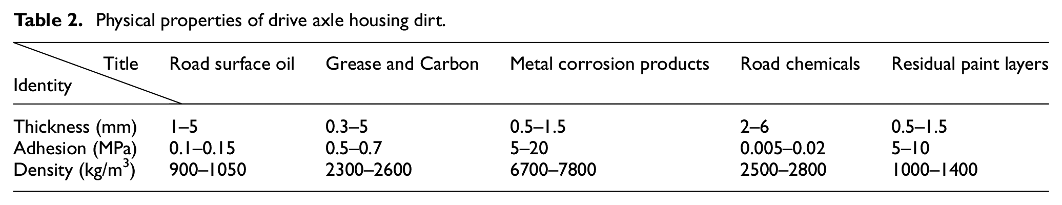
Different types of contaminants have distinct properties. For example, some contaminants exhibit strong adhesion, firmly bonding to the surface of the components, making them difficult to remove. The physical properties of common contaminants are outlined in Table 2 below.
(2) Cleaning Process Selection.
Physical properties of drive axle housing dirt.
The cleaning process has reached a relatively mature stage, with several common methods employed in production, including solution drenching, high-pressure spray washing, jet cleaning, immersion cleaning, brushing, and ultrasonic cleaning. The selection of cleaning methods in practice depends on the characteristics of the parts and the type of contamination they exhibit.
① Solution Drenching: Suitable for applications requiring high mobility.
② High-Pressure Spray Washing: Effective for quickly rinsing large surface areas.
③ Jet Cleaning: Efficient for removing localized contaminants.
④ Immersion Cleaning: Particularly useful for complex structures or parts with hard-to-reach surfaces.
⑤ Brushing: Ideal for addressing detailed or stubborn contaminants.
⑥ Ultrasonic Cleaning: Provides microscopic cleaning, effectively removing fine particles.
Each method has its own advantages, and the choice depends on factors such as the size, shape, and material of the part, as well as production requirements. A comprehensive evaluation considering efficiency, cost, and environmental impact can lead to the most effective cleaning process.
Based on a pre-production practice comparison of automotive drive axle shell cleaning efficiency (shown in Figure 4 below) and considering the characteristics of the parts and cleaning efficiency in pre-tests, ultrasonic cleaning technology proves to be more suitable for axle shell remanufacturing due to its efficiency and environmental friendliness.
(3) Configuration of Cleaning Agent.

Cleaning efficiency of different cleaning processes for axle housing products.
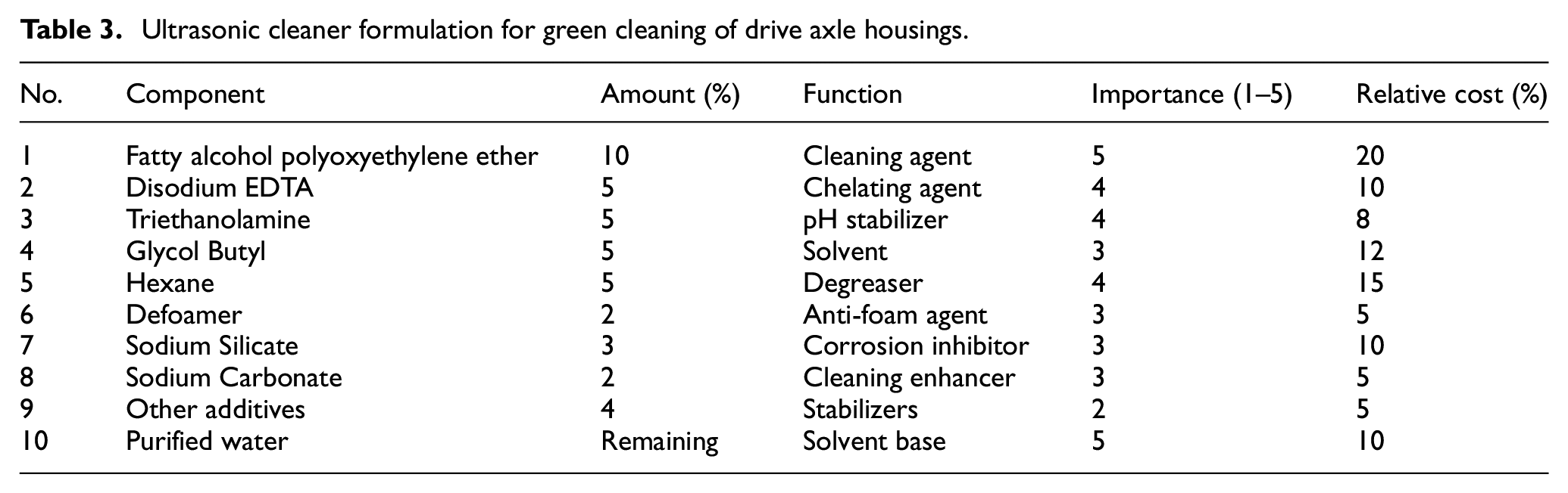
Common contaminants found on automotive drive axle housings exhibit varying solubilities, primarily categorized as water-soluble and oil-soluble dirt. Due to the differences in the physical and chemical properties of these contaminants, the ultrasonic cleaning process requires the selection of appropriate cleaning agent components. These components may include water, surfactants, solvents, chelating agents, buffers, preservatives, descaling agents, and others. Their main component, function, importance, and relative cost are shown in Table 3 below.
(4) Implementation of the Cleaning Process.
Ultrasonic cleaner formulation for green cleaning of drive axle housings.
Based on the ultrasonic cleaning formula and the mechanical properties associated with ultrasonic cleaning, the process flow for the remanufacturing cleaning of the drive axle shell is outlined in Table 4 below.
(5) Effect of Remanufacturing Green Cleaning Process.
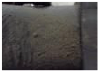
Implementation of remanufacturing cleaning process.

Following ultrasonic cleaning, the appearance of the automotive drive axle shell shows significant improvements. Compared to traditional methods, the overall visual cleanliness of the parts, especially the more complex axle shell structure, is notably enhanced. Additionally, ultrasonic cleaning eliminates the flammable and explosive risks associated with traditional gasoline-based cleaning, significantly increasing the safety of the process. This cleaning method also demonstrates greater efficiency, as ultrasonic cleaning agents replace manual operations, thereby reducing labor intensity. A comparison of the axle housing before and after cleaning is shown in Table 5 below.
Axle housing cleaning before and after comparison.

Non-destructive testing program
(1) Pre-Treatment Before Testing.
Before testing, it is essential to eliminate any residual height from the weld to be inspected, focusing on key areas such as the weld itself, surface scars, knock marks, and other defects. This ensures a consistent mechanical relationship between the surface and the base material. During the preparation process for subsequent polishing with 320#, 400#, 500#, and 600# abrasives, it is recommended to use an electric grinding wheel to prevent excessive heat generation, which could alter the original stress state of the weld.
The chemical polishing solution is prepared by mixing 14 mL of HF, 80 mL of H2O2, and 50 mL of H2O. Using a plastic dropper, apply an appropriate amount of polishing solution to the weld surface. Then, using an index finger, gently rub the surface repeatedly until most of the polishing solution is absorbed. Add more solution as needed and continue the process, observing the surface for changes. Stop polishing once the polishing scratches disappear. Afterward, rinse the weld surface with hydrogen peroxide promptly to prevent oxidation and rust. The chemical polishing process is shown in Figure 5.
(2) Configuration of Instrument Parameters and Selection of Detection Points.

Chemical polishing.
The residual stresses of the samples were measured using a Proto Residual Stress Analyzer (XRD), following the procedures outlined in ASTM E915-90. The residual stresses in the weld joints near the flange of the drive axle housing, under varying fatigue life conditions, were determined using the isotropic method. This method employed Kα-rays from a Cr target with an operating voltage of 20 kV, an operating current of 4 mA, and a β-angle of 30°. A total of 11 test points were selected on the sample surface, and each point was measured with a dual detector, resulting in 22 data points. The analysis focused on the (2) crystalline plane with a Bragg angle (2θ) of 156° and an optical slit of 1 mm. Each test point had an exposure time of 1 min, with 15 exposures per second. Peak position localization and peak shape fitting were conducted using Pearson’s method.
To address the limitation imposed by the flange on the oscillation amplitude of the instrument probe, the longitudinal stress of the weld was detected using the same inclination method, while the transverse stress was measured using the side inclination method. The selection of detection points followed this principle: one point was taken every 1 mm along the center of the polished surface until it extended more than 5 mm beyond the body of the half-shaft casing. Subsequently, regions with larger residual stresses, as well as the weld edges, were densely sampled. The schematic representation of the specific distribution of inspection points is shown in Figure 6 below.
(3) Key Points in the Inspection Process.

Schematic diagram of the distribution of detection points.
To ensure consistent detection of the same area during each measurement, the following steps are recommended: First, use a large triangular plate with one right-angled edge passing through the center of the polished surface and the other edge resting against the flange. Then, with a thick-tipped marking pen, draw a vertical line along the right-angled edge of the triangular plate on the flange as a reference. Next, align the probe with the marking line, initialize the instrument axis, and use the instrument software to precisely control the probe’s movement outward by 25 mm along the marking line. The detection process is illustrated in Figure 7 below.
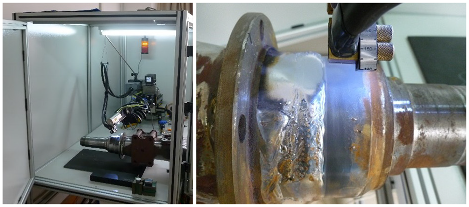
Schematic diagram of welded seam inspection.
Remanufacturing process technology program
(1) Technical Solution for the Remanufacturing Process of Automobile Drive Axle Shell Body Damage via Overlay Welding.
In this study, a 510L axle housing piece was selected as the base material for overlay welding, which shares the same material composition as the body of an automotive drive axle shell. Two types of welding wires, H13CrMoA and ER50-6, were chosen for the welding process. To prepare the surface of the base material, the oxidized layer was removed using a hand-grinding wheel. Additionally, any residual oil in the welding area was carefully wiped off with anhydrous ethanol to ensure optimal bonding between the welding wire and the base material. This meticulous preparation is essential for achieving a strong and effective weld.
The surfacing process employed the YJG-1 sub-laser instantaneous fusion method, with a welding machine frequency of 1 Hz. Time and energy adjustments were set to 95, and argon was used as the protective gas with a flow rate of 10 L/min. The surfacing was performed using the hand-feeding method on the axle housing, employing both H13CrMoA and ER50-6 wires for single and double-layer surfacing. The surfacing area measured 2 cm × 2 cm, with a single-layer thickness of 1.2 mm and a double-layer thickness of 2.2 mm. The overlay specimens, with a total thickness of 2.4 mm for the double-layer surfacing, were allowed to cool naturally in the air for 24 h after welding. This post-welding step aimed to release thermal stresses and provide adequate preparation for subsequent residual stress testing of the overlaid specimens, as illustrated in Figure 8 below.
(2) Technological Program for the Remanufacturing Process of Half-Shaft Casing Wear via Super Abrasion Brush Plating.
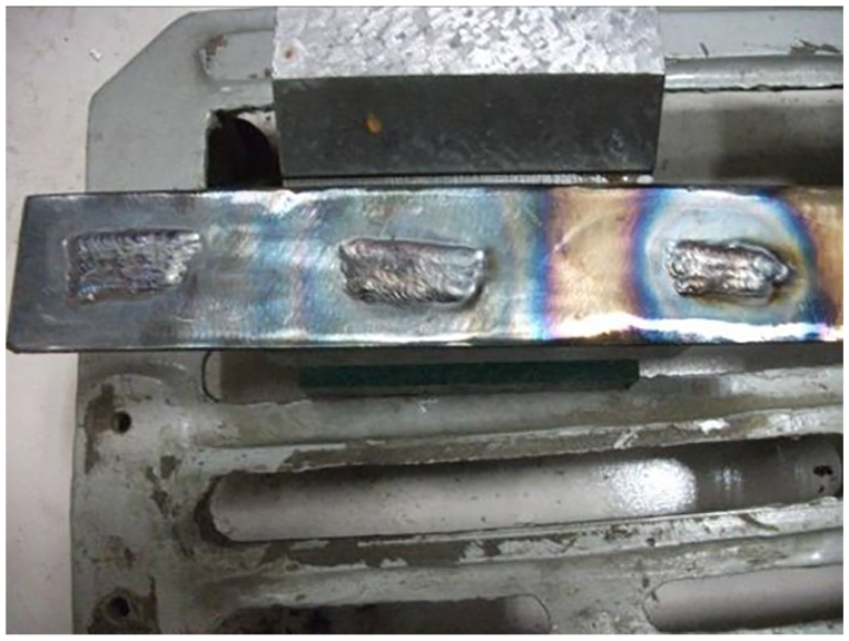
Air-cooled axle housing sheet after surfacing.
The experimental subject is the half-shaft casing, made from 40Mn material. To address oil contamination on the surface of the remanufactured half-shaft casing blank, a self-configured cleaning agent was selected. Using the JK-250DB ultrasonic cleaner with the self-prepared aqueous green cleaning agent, the cleaning process was conducted at a temperature of 60°C–70°C for 3 min to effectively remove oil contamination. After cleaning, the half-shaft casing was securely clamped onto a modified brush plating machine. Sequential sanding with 60# and 180# abrasive belts was performed to eliminate abrasions and scuffs, ensuring a clean and smooth surface for the subsequent remanufacturing processes.
To further prepare the surface for brush plating, degreasing cotton soaked in anhydrous ethanol was used to thoroughly wipe the polished half-shaft casing. This step is critical for removing any remaining oil. The brush plating power supply was then activated, with the frequency adjusted between 800 and 1000 Hz, and the duty cycle modulation set between 40% and 100%. The electro-purification process began with 1# electrolytic de-oiling dissolution, followed by the application of 2# activation solution for strong activation and 3# activation solution for weak activation. A special nickel priming layer was then applied, with a voltage set to 12 V to generate an alkali copper sandwich layer. Finally, the working layer was deposited through fast nickel plating. The results of this process are shown in Figure 9.
(3) Micro-Arc Deposition Remanufacturing Process for Shaft Head Thread Damage.

Brush plating remanufactured restoration layer.
To achieve precise local remanufacturing of threads with minimal thermal impact, micro-arc deposition technology was employed in combination with the slattern socket buckle method for the experimental process. A slat wrench designed to match M64 × 1.5 was created to meet the remanufacturing requirements of the thread socket buckle. The process utilized a metal surface strengthening repair machine and a nickel electrode rod, with the following parameters: power set at 1500 W, working voltage at 22 V, frequency at 300 Hz, argon flow rate between 10 and 15 L/min, and electrode rod rotational speed at 1600 r/min. The damaged threads were repaired using micro-arc deposition until they slightly exceeded the cusp position. The specific results of this process are illustrated in Figure 10.
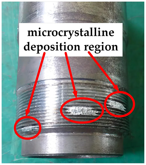
Damaged threads subjected to micro-arc deposition.
The damaged half-shaft casing threads were carefully repaired using various grinding tools, including different files, until the threads were initially formed. The half-shaft casing was then securely positioned on a vise stand. An M64 × 1.5 round plate tooth, along with a plate tooth wrench, was used for snapping, as shown in Figure 11 below. This process ensures the effective restoration of the threads, contributing to the overall remanufacturing of the damaged half-shaft casing.
(4) Challenges and Solutions in Implementing Experimental Restoration Processes.

Half-shaft sleeve thread repair molding.
The experimental restoration process integrated the practical application of three key technologies – Cladding, Brush Plating, and Micro-Arc Deposition (MAD) – to address critical challenges and ensure the efficiency and reliability of the remanufacturing process. Effective solutions were proposed for each challenge, as detailed below:
① Optimization of Cladding Technology.
The primary challenges in the cladding process involved preventing thermal deformation and ensuring weld layer uniformity. These issues were addressed by enhancing surface cleaning procedures to eliminate oxidized layers and oil contamination that could compromise weld quality. Parameter optimization and layering techniques were employed to achieve highly uniform fusion welding in the cladding area. Additionally, natural cooling and aging treatments further improved the mechanical properties of the welded layer, providing a robust foundation for subsequent analyses.
② Improvement of the Brush Plating Process.
Brush plating faced significant challenges in achieving uniform deposition on complex geometrical surfaces. To address this, the process dynamically adjusted frequency and current density while incorporating a multi-step cleaning and activation procedure. These measures ensured consistent plating across both flat and curved areas. Furthermore, the inclusion of a specially designed nickel base layer enhanced plating adhesion and satisfied the mechanical requirements of remanufactured components.
③ Refinement of Micro-Arc Deposition (MAD) Technology.
Thread repair using MAD technology required balancing high precision with minimal thermal impact. Precise control of process parameters, including working voltage and argon shielding, ensured the uniformity and density of the coating. Post-treatment processes further enhanced the coating’s hardness and durability, enabling the repaired threads to meet the functional demands of practical applications.
Results and discussion
Analysis of non-destructive testing data for remanufactured automotive drive axle housing blanks
The X-ray Residual Stress Analyzer not only measures residual stress within a material but also provides additional valuable data. This instrument enables the determination of the dispersion of the residual stress test results, the diffraction intensity of the material, and the half-height width of the diffraction peaks. The dispersion and diffraction intensity are closely related to the material’s structural properties, while the half-height width of the diffraction peaks is indicative of the micro-plastic deformation within the material. The longitudinal residual stress results are shown in Figure 12 below.

Longitudinal residual stress distribution.
The stress distribution diagram reveals the following key observations:
(1) Compressive Stresses: Varying magnitudes of compressive stresses are observed around the center of the weld.
(2) Transition from Compressive to Tensile Stress: Moving away from the flange, starting at the center of the weld and extending toward its edge, the residual stress gradually transitions from compressive to tensile stress.
(3) Reduction in Residual Stress: Apart from areas near the center of the weld (particularly around points 1 and 3), where residual stress remains relatively stable, other regions experience a noticeable reduction in residual stress as the number of loading cycles increases. From a residual stress perspective, this trend is beneficial for reinforcing the structural strength of the weld.
(4) Change in Longitudinal Residual Stress: A significant change in longitudinal residual stress is observed in part 4. After 100,000 loading cycles, the overall stress change is relatively small. However, after 300,000 loading cycles, residual stress in this area increases, although it remains lower than that of the new axle housing. Given that the axle housing is already in a “service” state, the residual stress, combined with additional stress from external loads, may reach or exceed the yield limit of the axle housing, potentially leading to its fracture. This makes it a critical monitoring point for assessing the fatigue life of the automotive drive axle shell.
The synchronous analysis of the residual stress detection results along the horizontal line is shown in Figure 13 below.

Transverse residual stress distribution.
From the stress distribution diagram, the following observations can be made:
(1) Residual Stress Variation: Except for the noticeable change in residual stress near the edge of the weld in part 3, which shows more pronounced variation with increasing loading cycles, the residual stresses in other regions exhibit staggered curves. These curves lack a distinct regular pattern and are therefore unsuitable for the formulation of standardized testing procedures.
(2) Transverse Residual Stress: Regardless of whether the axle housing is new or has been loaded, the transverse residual stress at the No.1 end does not exhibit tensile stress. This indicates that the transverse residual stress in this area will not negatively affect the fatigue strength of the weld.
After analyzing the stress, the primary factor influencing the fatigue life of the automotive drive axle shell was successfully identified. Based on this foundation, a neural network model was developed to predict the remaining life of the automotive drive axle housing. After pre-processing finite element analysis and statistical research, it was determined that the fatigue life of the steel plate press-welded automotive drive axle housing is mainly constrained by the weld seam where the housing body is joined to the half-shaft casing.
The characteristic parameters at the weld seam are used as the input layer, denoted as x i (i = 0, 1, 2, 3, …, n), where n represents the number of units in the input layer. The hidden units are represented by y i (j = 0, 1, 2, …, m), where m is the serial number of the hidden unit. The hidden layer can consist of one or more layers, and the activation function employed is a sigmoid-type function. Finally, the output layer is represented by z k (k = 1). Through the design of this neural network, a life prediction model for the drive axle shell is established, as shown in Figure 14 below.

Neural network model.
The feature parameters were obtained through bench tests, and the neural network model was employed to accurately assess the remaining life of key components, optimizing resource utilization efficiency when combined with remanufacturing strategies.
(1) Extraction of Feature Parameters and Construction of Training Samples
Residual stress, deformation, and magnetic field strength gradient (Kmax) were extracted as the primary feature parameters from tests conducted on drive axle shells of the same automobile model. The data distribution followed a lognormal or Weibull distribution, with the fatigue life interval defined as (103, 106).
The degree of stress concentration was characterized using the ratio parameter m. Here, Kmax represents the magnetic field intensity gradient at the stress concentration, while Kavg denotes the average magnetic field gradient, calculated as:

Where K i represents the magnetic field strength gradient of the test at the i time, and n is the total number of tests. A value of m > 1 indicates significant stress concentration, which can result in a substantial reduction in fatigue life.
The training samples include the following input features:
X 1: residual stress (MPa); X2: deformation (μm); X3: magnetic field strength gradient (A/(m−1 mm−1)); X4: ratio parameter m; and the target output is the fatigue life N. Through the extraction of the above feature parameters and the processing of the data, the training data sample is obtained.
(2) Data Normalization
The significant differences in units and value ranges of the feature parameters can reduce learning speed or cause non-convergence when directly input into the network. To address this, MATLAB’s premnmx function is used to normalize the data, adjusting the input feature values and output values to the range [−1, 1]:

Here, Xmin and Xmax represent the minimum and maximum values of the original data, respectively. Similarly, the test data is normalized using the tramnmx function, and the simulation results are back-normalized using the postmnmx function for error analysis.
(3) Neural Network Training
The neural network is designed with a three-layer structure:
① Input Layer: Contains four nodes corresponding to residual stress, deformation, Kmax, and the ratio m.
② Hidden Layer: Based on Kolmogorov’s theorem, nine neurons are used with the Sigmoid activation function:

③ Output Layer: A single node outputs the predicted lifetime.
The training functions used are trainbfg (based on the BFGS quasi-Newton method) and trainbr (based on Bayesian regularization). The error function is defined as the mean square error (MSE):

where y
i
is the true lifetime and
The trainbr function further improves generalization by introducing a regularization term:

where λ is the regularization factor, controlling the complexity of the model. The training results indicate that trainbr achieves the lowest error and the best generalization performance.
(4) Model Validation and Analysis of Prediction Results
The detection data were input into the neural network model, and the remaining life was calculated using the following formula:

Where the median fatigue life is Nmedian = 8 × 10⁵, and the actual working life is Nused.
The relative error was determined by comparing the predicted life (Npredicted) with the actual life (Nactual) using the formula:
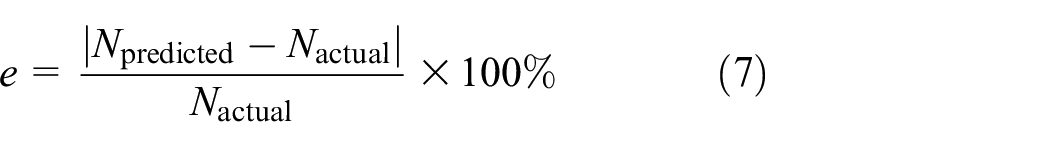
Figure 15 illustrates the predicted versus actual values for five samples at different service stages. The average error was 15.7%, with predicted values generally slightly lower than measured values. This conservative prediction provides a safety margin for screening remanufacturing candidates.
(5) Guidance for Remanufacturing Process Implementation

Comparison of predicted remaining life with measured values.
Based on the relationship between the predicted remaining life (Nremaining) and the median life (Nmedian), the following strategies are proposed:
①
The bridge shell has sufficient elastic reserves and is suitable for surface damage remanufacturing.
②
The bridge shell has limited elastic reserves and potential for repair. If damage is extensive and repair costs are high, scrapping is recommended. For isolated damage, repair may be attempted.
③
The bridge shell is nearing the end of its fatigue life and is recommended for direct scrapping.
Performance validation of remanufacturing processes
(1) Hardness Matching Analysis of Cladding Remanufacturing Repair Layer.
Surfacing is a critical process in the remanufacturing of automotive drive axle shell bodies. To assess the thermal influence induced by the surfacing process on the base material, five test points were uniformly selected within 5 mm of the 510L base material and its surfacing layer. Hardness tests were performed at these points to evaluate the thermal impact of the cladding process. The hardness values of the base material, the heat-affected zone near the cladding layer, and the areas subjected to the same cladding process and wire conditions were recorded, calculated, and averaged. The results of the hardness tests are presented in Figure 16 below.

Hardness distribution of cladding remanufactured layers.
The hardness of single and double-layer overlay specimens using H13CrMoA and ER50-6 wires, respectively, in the direction of the weld channel shows slight fluctuations around HRC24 and HRC6.5. The base material has a hardness of approximately HRC6.5, with the heat-affected zone exhibiting a similar hardness of HRC6. Experimental results indicate that the hardness of each cladding layer, achieved through the YJG-1 sub-laser instantaneous melting on the 510L base material, is uniformly distributed. Notably, the cladding layer prepared with H13CrMoA wire has significantly higher hardness than the 510L base material, while the ER50-6 cladding layer demonstrates hardness similar to that of the base material. The thickness of the cladding layer has minimal impact on the hardness of the specimen. Although the heat-affected zone exhibits slightly lower hardness than the base material, this reduction is not significant, and certain phase transition zones do not experience localized softening. In conclusion, for aligning with the surface hardness requirements of the axle housing and adhering to wire selection principles, the use of ER50-6 wire is more advantageous.
(2) Performance Analysis of Half-Shaft Casing Brush Plating Remanufacturing Repair Layer.
Wire-cut samples measuring 20 mm × 20 mm × 10 mm were used to prepare the specimens for testing. The X-ray diffractometer employed in this study was the D/MAX2500V. Brush coating specimens were prepared, and the resulting X-ray diffraction spectra were converted into binary format data files using Jade software. The spectra obtained were then imported and analyzed, as shown in Figure 17 below.

Import of X-ray diffraction patterns.
Phase analysis was conducted by integrating the pre-imported ICDD PDF card index in Jade. The Search/Match (S/M) tool in the toolbar was used to search for items, displaying the top 100 most probable phases based on the match results. These phases were listed in descending order according to the reciprocal of the match rate (FOM value), with a smaller FOM value indicating a higher match rate. Although lattice distortion may cause deviations when comparing spectral lines between the standard card and the specimen, this method generally allows for the detection of the primary phases. The main identified phases are presented in Table 6.
The main phase composition of the coating.

The results indicate that the specimen primarily consists of Ni and Ni in solid solution, which is consistent with the use of fast nickel as the working layer. This suggests that the remanufacturing deposition of the brush plating layer adhered to the process protocols, with minimal introduction of impurity components. Detailed test results can be exported using the Print tool, as shown in Figure 18.

Sample measurement spectral lines and PDF standard spectral lines.
Initiate the peak search tool in Jade using the “second-order derivative” principle, checking for values reaching 0 to identify peaks on the spectral line. To avoid misidentifying local undulations as “peaks,” it is recommended to smooth the data before conducting the peak search, thereby minimizing the risk of errors in Jade’s analysis. After performing the peak search, use the command “View → Report → Report → Files → Peak Search Report” to access the peak search report, as shown in Table 7 below.
Report on the search for peaks.

The peak curve analysis report provides parameters such as peak angle, background line height, and peak height, with half-height width data available in the FMWH column. Using Scheele’s equation, the grain size of the plated specimens was calculated to be approximately 15 nm. This grain size is significantly smaller than that achieved through DC brush plating, which has positive implications for enhancing the anti-wear performance of the remanufactured repair layer.
(3) Analysis of Micro-Arc Deposition Molded Joints for Axle Head Thread Damage
To assess whether the thread remanufacturing process, following micro-arc deposition with socket buckle re-forming, induces stress concentration, an EMS2000+ metal magnetic memory intelligent detector was used to measure stress on the remanufactured casing threads. Magnetic memory detection requires a relative motion between the probe and the workpiece, and efforts were made to maintain uniform motion during the process. The half-shaft casing was mounted on a lathe chuck with adjustable speed. The entire perimeter of the remanufactured thread was sequentially marked for line detection, and the workpiece was oriented in a north-south direction. The following instrument parameters were set: a probe lift-off value of 1 mm, a moving speed range of 7–9 r/min. The inspection process is illustrated in Figure 19 below.

Magnetic memory inspection of threaded metals for microarc deposition molding.
Magnetic memory testing of the remanufactured threads on the half-shaft casing revealed a maximum gradient change value, Kmax, of only 3.4 A/(m−1 mm−1), indicating a relatively small variation. This observation suggests a uniform stress distribution, and the results demonstrate that micro-arc deposition did not introduce any new stress concentration areas in the remanufactured threads, as shown in Figure 20 below.
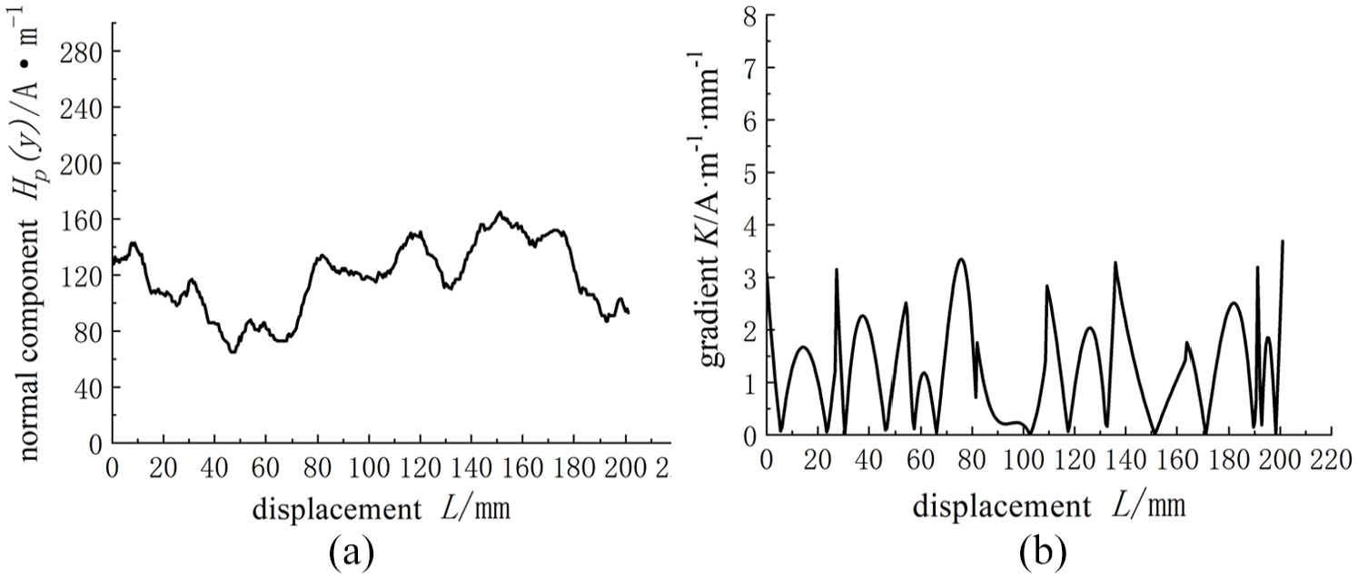
Metal magnetic memory test results: (a) normal component displacement monitoring map and (b) variable gradient displacement detection chart.
The effectiveness of the micro-arc deposition remanufactured threads was confirmed through thread fit experiments. The results showed that the threads created by the micro-arc deposition remanufacturing process allowed for the smooth insertion of the large nut at the axle head. Additionally, the threads provided a secure connection to the end, as illustrated in Figure 21.
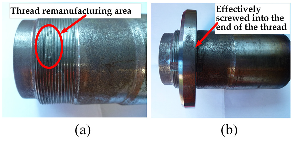
Remanufactured thread fit experiment.
The experimental findings strongly confirmed the effectiveness of the half-shaft casing thread remanufacturing process using micro-arc deposition. The remanufactured threads exhibited excellent performance, free from deposition defects and additional stress concentration areas. Notably, the thermal impact of the micro-arc deposition process was relatively low, allowing the workpiece to be handled during deposition. The temperature in the highest area remained below 200°C for extended periods, minimizing thermal damage to adjacent threads. The micro-arc deposition process, with its localized application to damaged threads, demonstrated high efficiency and effectively addressed remanufacturing challenges within a specific damage range.
Conclusions and future work
In this study, the pretreatment of automotive drive axle shells was achieved using ultrasonic cleaning, combined with residual stress detection to establish a model correlating residual stress with the remaining life of failed axle shells. The reliability of the proposed repair processes was also verified. The main conclusions are as follows:
(1) The annular weld is identified as the critical detection area, with longitudinal residual stress showing a correlation with diffraction peak changes and the number of fatigue loadings. Neural network model predictions indicate that 1/3 and 1/4 of the median life can serve as fatigue life warnings and the lower limit for remaining life control, respectively.
(2) The hardness of the argon laser cladding repair layer reaches HRC6, comparable to the substrate, with no reduction in hardness observed in the heat-affected zone, demonstrating its suitability for remanufacturing the axle housing body.
(3) The brush plating repair layer exhibits a grain size of approximately 15 nm, free of impurity element deposition, and demonstrates fine-grain strengthening effects, making it suitable for wear repair.
(4) The maximum magnetic memory gradient change in the threaded area repaired by micro-arc deposition is only 3.4 A/(m−1 mm−1), ensuring smooth and reliable nut connections.
Future studies will focus on increasing the sample size and evaluating the proposed method under a wider range of environmental conditions, such as extreme temperatures, humidity, and varying load scenarios. These efforts aim to enhance the generalizability of the findings across diverse operational settings and provide a more comprehensive understanding of the method’s applicability.
Footnotes
Handling Editor: Sharmili Pandian
Author contributions
Yechao Shen: conceptualization, methodology, validation, formal analysis, investigation, resources, data curation, writing – original draft preparation, writing – review and editing, visualization, supervision, project administration, funding acquisition; Jinlin Huang: conceptualization, validation, investigation.
Declaration of conflicting interests
The author(s) declared no potential conflicts of interest with respect to the research, authorship, and/or publication of this article.
Funding
The author(s) disclosed receipt of the following financial support for the research, authorship, and/or publication of this article: This research was funded by the Support Program for Outstanding Young Talents in Universities in Anhui Province (gxyq2022275), the Development and application of industrial network communication technology service platform (HX2024060) and the Natural Science Research Project of Anhui Province of P. R. China (2024AH050219).