
Abstract
The phenomenon of abnormal axle box vibration in high-speed railway vehicles was analyzed based on measured vertical acceleration data of the axle box at different vehicle speeds. The results show that abnormal vibration occurs when the vehicle speed exceeds 350 km/h, with the frequency mainly concentrated around 40 Hz. To investigate the cause of the abnormal vibration, a vehicle-rail coupling system dynamics model was established, and the cause was analyzed through dynamic simulations. The analysis reveals that, when the vehicle speed exceeds 350 km/h, the coupling effect between wheel eccentric excitation frequency and P2 resonance frequency leads to vertical abnormal vibration of the axle box, with the most intense vibration occurring at 400 km/h. To resolve this issue, a solution is proposed to install a Dynamic Vibration Absorber (DVA) in the vertical direction of the axle box. When the mass ratio of the DVA is between 0.15 and 0.2 and the damping ratio is between 0.12 and 0.2, this method effectively suppresses the abnormal vibration of the axle box at 400 km/h, while avoiding excessive vibration acceleration at lower or higher speeds. This approach provides an effective solution for controlling abnormal axle box vibrations in high-speed railway vehicles.
Introduction
With the increasing operating speed of high-speed trains, abnormal vibration issues in vehicles have become increasingly prominent. Particularly, when the speed exceeds 400 km/h, excitations at the wheel-rail interface, such as track irregularities and wheel polygonal wear, can induce severe vibrations. These vibrations propagate from the axlebox to the bogie frame, carbody, and even the track system, posing significant risks to the safe operation of railway vehicles. Therefore, under the background of speed enhancement, it is especially critical to investigate the abnormal vibration problems of 400 km/h-class railway vehicles and propose corresponding optimization solutions.
The abnormal vibrations of railway vehicles can generally be attributed to several causes, including wheel polygonal wear, rail corrugation, wheel-rail coupling resonance, abnormalities in drive and transmission systems, and suspension system failures. Among these, vibrations caused by abnormalities in drive and transmission systems or suspension component failures usually disappear after replacing the faulty equipment. In contrast, periodic excitations such as wheel polygonal wear and rail corrugation, as well as wheel-rail coupling resonance, are the primary causes of abnormal vehicle vibrations, which tend to reoccur with increasing operational mileage. At present, extensive research has been conducted on wheel polygonal wear and rail corrugation. Wu et al. 1 conducted tracking tests to summarize the development patterns of wheel polygonal wear and found that as train speed, the amplitude of polygonal wear, and its order increase, the fluctuation range of wheel-rail vertical interaction forces and the bogie vibration response grow significantly. Jiang et al. 2 developed a vehicle-track coupled dynamic model incorporating a flexible carbody to study the vibration response of the carbody under measured wheel polygonal excitations. Their results revealed that when a metro vehicle operates at 70 km/h, the first- and second-order wheel out-of-roundness can excite the diamond-shaped and torsional modes of the carbody, which are direct causes of carbody abnormal vibrations. Yang et al. 3 discovered through line testing that locomotives with severe wheel polygonal wear could trigger VMS (Vehicle Monitoring System) alarms, with significant impacts on both longitudinal and lateral vibrations of the vehicle. Shi et al. 4 found that, for metro vehicles, resonance occurs when the frequency of 61.5 mm wavelength rail corrugation matches the natural frequency of axlebox suspension lugs at a certain speed, leading to the fracture of the axlebox lugs.
In the research on wheel-rail coupling resonance, Nielsen et al. 5 suggested that the P2 resonance force in the wheel-rail system induces vertical vibration of the wheelset, leading to uneven wheel wear and promoting the formation of first to fifth-order wheel polygonal wear. Morys 6 established a coupled vehicle-track dynamic model for ICE trains to investigate the mechanism of wheel polygonal wear formation. The results indicated that the flexible deformation of the track exacerbates wheel-rail coupling resonance, thereby accelerating the evolution of wheel polygonal wear. Johansson and Andersson 7 developed a mathematical model of vehicle-track interaction and studied the mechanism of wheel polygonal wear formation using an iterative dynamic simulation method based on Archard’s wear theory. Their findings revealed that P2 resonance at approximately 40 Hz and track reverse resonance at 165 Hz could induce fifth to seventh-order wheel polygonal wear. Tang et al. 8 compared the coupled natural frequencies of vehicle-track systems with the passing frequencies of rail corrugation. Their research demonstrated that wheel-rail P2 resonance is a critical factor in the formation of corrugation with wavelengths between 160 and 200 mm. Additionally, the vertical bending vibration of rails together with track slabs was found to induce 100 mm wavelength corrugation, while the vertical bending vibration of rails relative to track slabs led to the formation of 40 mm wavelength corrugation.
To address the abnormal vibrations caused by wheel polygonal wear and rail corrugation, engineering practices typically involve regular wheel re-profiling and rail grinding to maintain the surface roughness of wheels and rails within a reasonable range. Some studies recommend timely wheel re-profiling to control the abnormal vehicle vibrations it induces, 2 while others suggest regular rail grinding as an effective method, 4 both achieving satisfactory results. However, these approaches fail to fundamentally address the system-level abnormal vibrations caused by resonance, necessitating frequent maintenance of wheels and rails, which incurs significant labor and resource costs. At the vehicle design stage, structural modal optimization can be performed to prevent flexible mode resonance, 9 or active or semi-active dampers can be employed to suppress vibrations. However, for in-service vehicles experiencing coupling resonance, these solutions often involve high costs and lengthy implementation periods. In contrast, the use of dynamic vibration absorbers for vibration suppression has gained attention due to its simplicity, cost-effectiveness, and efficiency. Currently, the application of DVA in railway vehicles primarily targets structures such as tracks, track slabs, and wheels, aiming to suppress wheel-rail coupled vibrations and noise. However, research on installing DVA at the axlebox to mitigate abnormal vibrations remains limited. Wu10,11 proposed the use of rail-mounted DVA to address rail corrugation. The results demonstrated that for tracks with short sleeper spacing, the installation of rail-mounted DVAs effectively mitigates the development of rail corrugation and reduces wheel-rail noise. Zhang et al. 12 suggested using DVA to control low-frequency vibrations of floating slab tracks under wheel-rail dynamic interactions. Their results showed that appropriately designed DVA could effectively suppress the low-frequency vibrations of the floating slab and reduce the transmission of corresponding frequency spring forces to the subgrade. Liu et al. 13 demonstrated that installing DVA on the spokes of train wheels reduced vibrational noise radiation by 6 dB. Sun et al. 14 proposed a multi-degree-of-freedom dynamic vibration absorber (MDOF DVA) mounted beneath the carbody to suppress multi-directional vibrations of high-speed train carbodies effectively. Liu and Shao 15 used finite element software to analyze the vibration reduction performance of rail-mounted DVAs, confirming their effectiveness. You et al. 16 introduced a method utilizing multiple DVAs to control localized excessive vibrations, showing through calculations that the method significantly reduces target modal vibrations and improves ride comfort. Sun et al. 17 developed a vertical two-degree-of-freedom low-frequency DVA based on acceleration feedback to control the low-frequency vertical bounce and pitch vibrations of the carbody, achieving effective suppression of these modes.
In summary, research on abnormal vibrations in railway vehicle systems has been extensive, but most studies focus on metro vehicles, locomotives, and EMUs operating at speeds below 350 km/h. For high-speed EMUs operating at 400 km/h, the characteristics of abnormal vibrations differ significantly, making it crucial to study and control such typical abnormal vibrations. This study investigates the abnormal axlebox vibrations of high-speed trains at 400 km/h. Based on line test data, the frequency of abnormal axlebox vibrations was identified, and the underlying causes were analyzed and verified through simulation. The results confirmed that the abnormal vibrations are induced by the coupling resonance of wheel eccentric excitation and P2 forces. To address this issue, a vibration mitigation method employing a DVA installed at the axlebox was proposed. Simulation results indicate that a DVA with appropriately designed stiffness, damping, and mass can effectively suppress abnormal axlebox vibrations at 400 km/h. Furthermore, the proposed solution does not result in excessive vibration accelerations at either lower or higher speeds, demonstrating its robustness and efficiency.
The remainder of this paper is organized as follows: In Section “Typical abnormal vibration of axle box of high-speed railway vehicle,” a detailed analysis of the typical abnormal axlebox vibrations in high-speed trains is presented, and the potential cause-coupling resonance between wheel eccentric excitation and P2 forces is proposed. In Section “Model,” a vehicle-track rigid-flexible coupled model is developed, and its accuracy is validated. In Section “Abnormal vibration analysis of the axle box,” the established model is used to investigate the causes of abnormal vibrations in high-speed EMUs during high-speed operation. A vibration mitigation method utilizing a dynamic vibration absorber dynamic vibration absorberinstalled at the axlebox is proposed, and its vibration reduction effectiveness is studied.
Typical abnormal vibration of axle box of high-speed railway vehicle
According to the measured results of axle box acceleration when the vehicle is operated under different speed levels in Figure 1, it can be seen that when the vehicle is operated at a speed of more than 350 km/h, the phenomenon of abnormal vibration of the axle box will be obvious. Further analysis of the axle box vertical vibration acceleration spectra at different speeds yielded the following three characteristics: (1) abnormal vibration can only be formed at high speeds, 350 km/h revealed, a sharp increase in 380 km/h or so, and the speed of the vehicle reaches 400 km/h when the vibration is further amplified. (2) The frequency of abnormal vibration is concentrated, mainly in the vicinity of 40 Hz. (3) Abnormal vibration is related to vehicle speed, and the frequency of the main frequency of vibration increases linearly with the increase of vehicle speed.

Spectrum diagram of axle box acceleration in field test.
For some vibration components in the figure show a frequency and speed proportional to the relationship, mainly caused by cyclic excitation, such as track plates, track sleepers and wheel polygons, and so on. Among them, the more obvious ones are “periodic excitation 1” and “periodic excitation 2,”“periodic excitation 2” is coupled with the abnormal vibration region, and the excitation is coupled with the abnormal vibration region in the vehicle speed over 350 km/h. After the vehicle speed over 350 km/h, the excitation is coupled with the abnormal vibration region. After the vehicle speed exceeds 350 km/h, the excitation shows the phenomenon of being significantly strengthened.
From Figure 1, the “periodic excitation 2” with better coupling in the vibration zone may be caused by wheel polygons. Wheel polygons are widely present in railway vehicles, is an important factor in causing high-frequency wheel-rail impact, 18 from low-order to high-order has a variety of forms, and the formation of wheel polygons of different orders of the reasons are also different, usually vehicles in the production process due to alignment errors and uneven quality and other reasons for the existence of eccentricity of the wheel (first-order polygons), along with the operation of the vehicle to the higher-order development. 19 The impact frequency caused by wheel polygons is calculated as follows:

Where,
According to previous research, the vibration around 40 Hz is usually related to the P2 force, which is mainly formed by the impact effect of the vehicle excited by the track, with the frequency between 20 and 100 Hz, 20 which is manifested as the isotropic floating and sinking of the vehicle’s unsprung mass and the part of the rail below the wheelset, which is widely existed in the vehicle line test, and when the speed is higher, the P2 resonance effect will be more intense. 21 In the vehicle line test can be seen P2 resonance frequency and track structure form closely related, its frequency does not change with the speed, the wheel polygonal excitation brought about by the vibration has strengthened the role of the vibration, for the plate ballastless track, the P2 force resonance frequency is calculated as 22 :

Where,


Where,
According to the above content can be studied on the vehicle axle box vertical abnormal vibration problem cause to make speculation, the principle is shown by Figure 2. The solid line is the P2 resonance frequency, because its frequency position will not be affected by the vehicle traveling speed, so usually the P2 resonance frequency is more fixed. The dotted line is the wheel eccentricity excitation frequency change curve, the wheel eccentricity excitation frequency increases with the increase of the vehicle speed, and gradually approach to the more fixed P2 resonance frequency. When the vehicle operating speed reaches 400 km/h, the two coupling effect is the strongest, in the axle box triggered intense resonance effect, the formation of abnormal vibration of the axle box.

Principle of abnormal vibration.
Model
Vehicle dynamics model
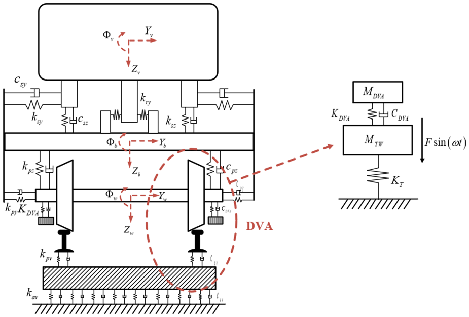
Based on the multi-body dynamics software SIMPACK, a high speed railroad vehicle trailer multi-rigid body dynamics model is established. Structures such as the vehicle body, frame, wheelset, and axle box of this vehicle model are regarded as rigid bodies, and their masses and moment of inertia are defined. For the vehicle body, frame, and wheelset, six degrees of freedom are retained by defining the articulation relationship, namely, extension, traverse, sinking, side-rolling, nodding, and rocking, while for the axle box, only the nodding degree of freedom is retained by defining the rotational articulation. The wheel treads are LMA type treads, and the rails are CHN60 type rails.
Meanwhile, there is a one-series suspension system between the axle box and the frame, which mainly includes the axle box positioning device, one-series steel spring and one-series pendant damper, etc., and there is a two-series suspension system between the frame and the vehicle body, which mainly includes the air spring, two-series transverse damper, transverse stop, and anti-snaking damper. The suspension elements in the vehicle are established in SIMPACK using the corresponding force elements, and the parameters of the vehicle suspension system are set through this vehicle parameter table. Among them, the two-series transverse dampers, transverse stops, and anti-snake travel dampers are considered for their nonlinear characteristics. The multi-rigid body dynamics model of the vehicle is shown in Figure 3, and the key parameters of the vehicle are shown in Appendix A.

Vehicle multi-rigid body dynamics model.
Flexible track model
During high-speed operation, the high-frequency vibration of the track plays a critical role in the vibration response of the vehicle. To account for the high-frequency vibration effects at the wheel-rail interface, it is essential to incorporate track flexibility into the model.23,24 For the flexible track model, since this study focuses only on the vertical flexible deformation of the track and its coupling effects on the vehicle system,25,26 a simplified model of the rail’s vertical motion, lateral motion, and torsional motion is established based on Timoshenko beam theory. The support provided by the fasteners is modeled as stiffness and damping, connecting the rail to the track slab. The track slab is further supported by a high-stiffness foundation. The basic parameters of the track model are provided in Appendix B. The equations of motion of the rail are classified into the vertical vibration, transverse vibration, and torsional vibration, which can be specifically written as. 26
Differential equation of vertical vibration:


Differential equations for transverse vibration:
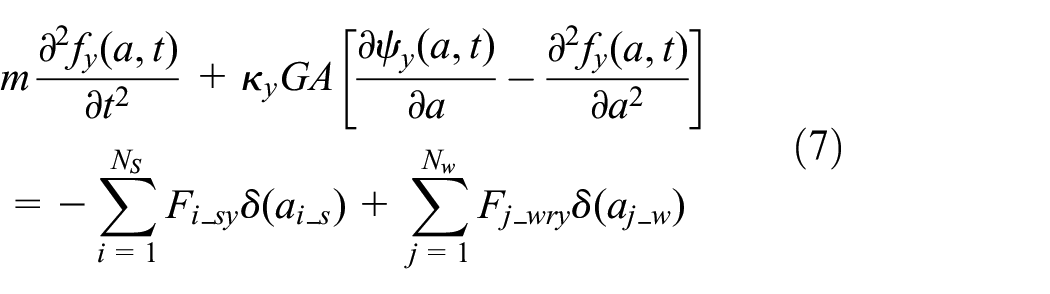
Differential equations for torsional vibration:

The meaning and value of specific parameters refer to the literature. 23 The track program is based on the modal superposition theory, due to the orthogonal nature of the regular function and regular coordinates, can be based on this property of the above track of the three degrees of freedom partial differential equations for simplification, 25 can be reduced to a system of ordinary differential equations, and finally solve the equations can be obtained at the corresponding moment of the track position response. The vehicle-track coupled dynamics model is shown in Figure 4.

Vehicle-track coupled dynamic model.
Model validation
Wheel eccentricity phenomenon widely exists in all kinds of railway vehicle wheels, the original wheel eccentricity phenomenon is usually caused by materials and manufacturing process, etc., and at the same time, the eccentricity phenomenon can not be well removed in the later turning repair. 26 Wheel eccentricity belongs to the first-order wheel polygon, and in this paper the wheel eccentricity model is given as a function in Rail-Wheel Pairs of SIMPACK software. The wheel diameter jump value with angle with wheel polygon is calculated as:

Where,
Theoretically, the wheel-rail impact brought by wheel eccentricity can form P2 resonance, and as long as the wheel eccentricity model is introduced, the P2 resonance between wheels and rails is followed in the simulation. However, in order to be more in line with the actual situation and more convincing, the welded rail joints are used to stimulate the P2 resonance, and the rail joint model is realized through MATLAB programming, and superimposed on the track uneven excitation with a spacing of 100 m as the line excitation to stimulate the wheel-rail P2 force resonance effect. In order to show that the model is able to accurately simulate the wheel-rail P2 force resonance frequency, the simulation results are compared with the results obtained through the wheel-rail P2 force resonance formula. In this paper, the wheel-rail P2 force resonance frequency is derived by providing a wheel-rail impact effect by applying a rail welded joint upset on the rail. Other basic parameters of the model are maintained unchanged and different fastener support stiffness conditions are set for comparison.
Figure 5(a) shows the vertical wheel-rail force when the vehicle passes through the rail joint, and it can be seen that when the wheel passes through the rail joint, a short duration and large amplitude impact force is generated, which is called the P1 force. This force is called the P1 force. Afterward, the impact force will be attenuated to form a P2 force with a longer action time but a smaller amplitude.

Verification of P2 resonance: (a) axis box vertical acceleration time domain and (b) frequency domain of shaft box vertical acceleration.
Figure 5(b) gives the simulation results of the resonance frequency of the P2 force of the wheel and rail under different fastener vertical support stiffness conditions on the rigid rail. It can be seen that when the fastener support stiffness is 20, 30, and 40 MN/m, the wheel-rail P2 force resonance frequencies are 38.6, 44.3, and 48.6 Hz, respectively, while the results calculated by the formula under the same vehicle track parameters are 36.9, 43.2, and 48.2 Hz, respectively, which can be seen that the wheel-rail P2 force resonance frequencies calculated by simulation and the formula are 36.9, 43.2, and 48.2 Hz. It can be seen that the difference between the wheel-rail P2 force resonance frequencies calculated by the simulation and the formula is small, and it can also be seen that there is no wheel-rail P2 force resonance phenomenon when the vehicle passes through the rail joints on the rigid rail.
Abnormal vibration analysis of the axle box
Causes of abnormal vibration
In order to correspond to the measured data where the vehicle is operated at different speed levels, this paper sets up uniform operation conditions where the vehicle speed is increased from 50 km/h with a span of 50–400 km/h at different speeds. In all cases, the vehicle is subjected to two excitations including the uneven excitation from the track and the wheel eccentricity excitation with 0.1 mm wheel diameter runout amplitude. The axle box vertical acceleration spectrum is shown in Figure 6, from which it can be seen that, due to the existence of wheel eccentricity, the main frequency amplitude of axle box vertical acceleration will increase with the increase of vehicle speed, but it will increase significantly after the speed of 350 km/h, and the vibration frequency concentrates around 40 Hz, which is consistent with the vibration characteristics in the test, so the vehicle-rail coupled dynamics model is able to restore the vehicle line in the test. This is consistent with the vibration characteristics in the test, so the vehicle-rail coupled dynamics model can restore the abnormal vibration phenomenon of the axle box in the vehicle line test.

Frequency domain diagram of vertical acceleration of axle box.
In order to analyze the effect of the wheel-rail P2 force resonance effect on the induced effect of this typical abnormal vibration, the response of the axle box vertical acceleration at different velocities with and without the wheel-rail P2 force resonance effect is compared, as shown in Figure 7. It can be seen that the P2 force can be introduced when the flexible track simulation is used, while this phenomenon is absent when the rigid track is used. Therefore flexible and rigid track simulations are used to realize the presence or absence of P2 force respectively.

Comparison of axle box acceleration in the frequency domain.
As can be seen from Figure 7, when there is no wheel-rail P2 force resonance involved, with the increase of the vehicle driving speed, the peak of the main frequency of the vibration formed on the axle box by the shock brought by the wheel eccentricity will continue to increase, which is different from the case in which the wheel-rail P2 force resonance is involved in the coupled vibration, so it can be concluded that it is due to the existence of the wheel-rail P2 force resonance that the coupling effect of the wheel eccentric excitation frequency and the wheel-rail P2 force resonance frequency is strongest when the vehicle speed is 400 km/h. P2 force resonance frequency when the vehicle speed is 400 km/h, the coupling effect is the strongest, which will strengthen the axle box vertical acceleration under this condition.
The above study shows that the typical abnormal vibration phenomenon in the high-speed test of railway vehicles is caused by the coupling of wheel eccentric excitation and wheel-rail P2 force resonance. In order to realize the suppression of abnormal vibration, adjusting the parameters to realize the mis-frequency can effectively suppress the vibration, but it is extremely difficult to adjust the parameters for the vehicles and rails that have been put into operation. Therefore, this paper investigates the vibration amplitude suppression effect of the additional dynamic vibration absorber at the axle box.
Power vibration absorber model
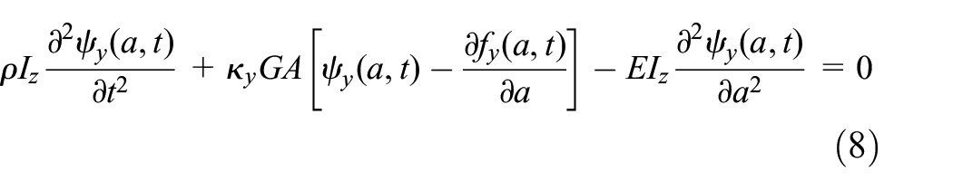
For wheel-rail P2 force resonance, the vibration is in the form of half of the unsprung mass of the vehicle and a section of rail below the wheels under the support of the under-rail foundation, such as fasteners, floating and sinking vibration. When the wheel and rail parameters are determined, the P2 force resonance frequency usually does not change with speed. And for the wheel eccentricity excitation, its frequency will change linearly with speed. Then the wheel-rail P2 force resonance with relatively stable frequency can be regarded as a vibration mode, while the wheel eccentric excitation whose frequency increases proportional to the vehicle speed can be regarded as an external simple harmonic excitation, and when a dynamic vibration absorber is attached, the unsprung mass of the vehicle as well as the rail system can be equated to the simplified model in Figure 8:
Equivalent model of P2 force resonance with dynamic vibration absorber.
The dynamic vibration absorber on the axle box is equivalent to a mass connected to the axle box by a certain stiffness and damping. In the equivalent model, the mass of the dynamic vibration absorber is M DVA , the stiffness is K DVA , and the damping is C DVA . The dynamic vibration absorber on the shaft box is equivalent to attaching this absorber device to the mass of the equivalent main vibration system of the wheel-rail P2 force resonance vibration type.
The purpose of this paper is to design the dynamic vibration absorber for the coupled vibration of wheel eccentricity excitation and wheel-rail P2 force resonance at the speed of 400 km/h, so the design frequency of the dynamic vibration absorber is 38.4 Hz. Therefore, the stiffness and mass of the dynamic vibration absorber must be satisfied 12 :

The mass, stiffness, and damping of the dynamic vibration absorber can be further expressed as 12 :
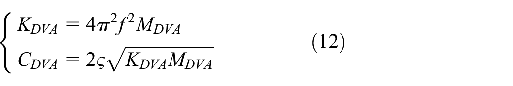
Where, M DVA , is the mass of the dynamic vibration absorber; K DVA , is the stiffness of the dynamic vibration absorber; C DVA , is the damping of the dynamic vibration absorber; ζ is the damping ratio; μ = M DVA /M TW is the mass ratio.
Therefore, after the design frequency of the dynamic vibration absorber is determined, its mass stiffness damping is transformed into a relational equation about the mass ratio and damping ratio. In the subsequent design of dynamic vibration absorber parameters, the mass ratio and damping ratio can be used to determine the specific values. In the dynamic model of the vehicle, a new dynamic vibration absorber inertia body is added at each of the four axle box positions of the bogie, the vertical freedom of motion between it and the axle box is retained by the No. 6 hinge, and finally the definition of the stiffness and damping is realized by the No. 43 force element. The vehicle dynamics model with axle box dynamic vibration absorbers is shown in Figure 9.

Vehicle bogie dynamics model with additional dynamic vibration absorber.
Analysis of the effect of dynamic vibration absorbers on the suppression of abnormal vibration
Set the mass ratio (corresponding to the mass of the vibration absorber) at 0.05 (48.18 kg), 0.1 (96.35 kg), 0.15 (144.53 kg), 0.2 (192.7 kg); and the damping ratio at 0.01, 0.04, 0.08, 0.12, 0.16, and 0.2 for the simulation conditions, respectively. The axle box vertical acceleration amplitude of the vehicle at 400 km/h is compared at each condition. The results are shown in Figure 10.

Effect of damping ratio on the amplitude of shaft box vertical acceleration at different speeds: (a) quality ratio 0.05, (b) quality ratio 0.1, (c) quality ratio 0.15, and (d) quality ratio 0.2.
Since the design frequency of the dynamic vibration absorber is 38.4 Hz which corresponds to the wheel eccentricity excitation frequency at 400 km/h, the dynamic vibration absorber has the best suppression effect at this speed level. Meanwhile, the smaller the damping ratio is, the better the vibration suppression effect is, but too small a damping ratio will lead to increased vibration when operating at 400 km/h on both sides of the road, which is the characteristic of the dynamic vibration absorber. At the same time, as the mass ratio increases, this new vibration peak will also move to both sides, but its vibration amplitude will be suppressed.
Therefore, the values of damping ratio and mass ratio of the dynamic vibration absorber are the key to design the dynamic vibration absorber. Based on the simulation results in this paper, several groups of working conditions in Table 1 are summarized, which can ensure the suppression of severe vibration of the vehicle at 400 km/h, and at the same time, the vehicle does not produce large abnormal vibration at low speed. Therefore, in order to design the power vibration absorber for the axle box of railway vehicles with an operating speed of 400 km/h, its mass ratio and damping ratio are controlled at 0.15–0.2 and 0.12–0.2 respectively, which can achieve better vibration suppression effect.
Vibration suppression effect of dynamic vibration absorber under the recommended damping ratio and mass ratio.

Conclusions
This study investigates the abnormal axlebox vibrations observed during line tests when high-speed railway vehicles operate at 400 km/h. Considering the wheel-rail coupling vibration effects, a vehicle–track coupled dynamic model is established to reproduce and analyze the phenomenon. The results indicate that the coupling between the wheel eccentric excitation frequency and the P2 resonance frequency at high speeds leads to abnormal axlebox vibrations. To address this issue, a vibration mitigation method employing a dynamic vibration absorber (DVA) installed at the axlebox is proposed. The design frequency of the DVA is set to match the abnormal vibration frequency observed at 400 km/h. Simulations are conducted to compare the vibration reduction performance of the DVA under different mass ratios and damping ratios. The results demonstrate that when the mass ratio is in the range of 0.15–0.2 and the damping ratio is within 0.12–0.2, the DVA effectively suppresses abnormal axlebox vibrations at 400 km/h. Moreover, the DVA does not induce excessive vibration accelerations at lower or higher speeds, showcasing its robustness across various operating conditions.
Footnotes
Appendix A
Key vehicle parameters.

| Parameters | Values |
|---|---|
| Vehicle fixing distance (mm) | 17,800 |
| Wheelbases (mm) | 2500 |
| Wheel rolling circle transverse span (mm) | 1493 |
| Total body mass (t) | 38.5 |
| Framing quality (t) | 2.16 |
| wheelsets quality (t) | 1.435 |
| Axle box quality (kg) | 160 |
| Vertical stiffness of a series of steel springs (kN/m) | 1089.2 |
| Damping of a system of pendant dampers (kN s/m) | 10 |
| Longitudinal stiffness of the positioning node of the swivel arm (kN/m) | 13,700 |
| Air spring static stiffness (MN/m) | 0.189 |
| Nodal stiffness of the transverse damper in the second system (kN/m) | 10,000 |
Appendix B
Key track parameters.

| Parameters | Symbol | Values |
|---|---|---|
| Young’s modulus of rails (N/m2) | 2.059 × 10¹¹ | |
| Shear modulus of rails (N/m2) | 7.9 × 10¹⁰ | |
| Density of rails (kg/m3) | 7860 | |
| Mass per meter of track (kg) | 60.64 | |
| Cross-section vertical shear shape factor | 0.5329 | |
| Cross-sectional transverse shear shape factor | 0.4570 | |
| Moment of inertia of the cross section against the y-axis ( m4) | 3.217 × 10⁻⁵ | |
| Moment of inertia of the cross section against the z-axis (m4) | 5.26 × 10⁻⁶ | |
| Torsional moment of inertia (m4) | 3.741 × 10⁻⁵ | |
| Lateral stiffness of fasteners (MN/m) | 29.4 | |
| Fastener lateral damping (kN s/m) | 52 |
Handling Editor: Sharmili Pandian
Declaration of conflicting interests
The author(s) declared no potential conflicts of interest with respect to the research, authorship, and/or publication of this article.
Funding
The author(s) disclosed receipt of the following financial support for the research, authorship, and/or publication of this article: This work was supported by the Science and Technology Research and Development Program Fund of China National Railway Group Co., Ltd. (Q2024J012).