
Abstract
The dynamic vibration absorbers have been applied to attenuate the critical or unbalanced vibration but may create the fluid-induced vibration instability in the rotor/seal system. The major purpose of this study is devoted to the effects of the dynamic vibration absorber on the nonlinear dynamic behavior and stability of the fluid-induced vibration in the rotor/seal system. The dynamic vibration absorber is attached on the shaft in the perpendicular directions. The model of the rotor/seal-dynamic vibration absorber system is established as the modified Jeffcott rotor system, and Muszynska nonlinear seal force is applied. The numerical method is used for the dynamic behavior analysis. The effects of the natural frequency and damping ratio of the dynamic vibration absorber on the dynamic behavior are discussed. The stability of the rotor/seal-dynamic vibration absorber system is judged by the eigenvalue theory. The variations of the instability threshold with the parameters of the dynamic vibration absorber are obtained. The results show that the instability threshold and instability vibration frequency are changed by the dynamic vibration absorber. The parameters of the dynamic vibration absorber must be selected carefully to avoid reducing the instability threshold and causing the instability vibration to occur in advance when the dynamic vibration absorber is applied to attenuate the critical or unbalanced vibration of the rotor/seal system.
Introduction
The excessive vibration in the rotating machinery is a serious problem. Especially, it leads to the rotor vibration faults, even causes the rotor to shut down quickly. The unacceptable vibration must be controlled to ensure the stable operation of the rotating machinery.1,2
Two kinds of methods, including adjusting the parameters and applying the external forces, are applied to attenuate the rotor vibration. The mass, stiffness, damping, and clearance can be adjusted to attenuate the excessive vibration. The rotor dynamic balancing is a common method to reduce the critical vibration when the rotor passes the critical speed. 3 Wang et al. 4 proposed the measurement point vector method to identify rotor unbalance while operating. The results from the dynamic analysis and numerical experiments provided that the method was efficient for the rotor balancing without test runs and external excitations. The shape memory alloy is commonly used to attenuate the rotor vibration by adjusting the stiffness. 5 Majewska et al. 6 presented the smart bearing support with the magnetic shape memory actuators to control the rotor vibration by the experimental work. Ribeiro et al. 7 performed the viscoelastic supports for the vibration control in the rotating machines. In addition, various types of dampers are used for the rotor vibration attenuation, for example, the magnetorheological squeeze film damper was utilized to reduce the rotor vibration by Hemmatian and Ohadi. 8 The bearing parameters can be self-adjusted by the tilting-pad journal bearing, and it is suitable to suppress the oil film whirl and whip occurring in the rotor system; for example, Chasalevris and Dohnal,9,10 Santos and colleagues,11–13 and Queiroz et al. 14 investigated the active tilting-pad journal bearing and the active fluid-film bearing to extend the stability margins for the rotor system. Another example of the parameter adjusting is the seal parameter adjusting. The rotating labyrinth gas turbine seal can disrupt the fluid flow in the seal, 15 and the parameters of the seal force were adjusted to suppress the fluid-induced vibration in the rotor/seal system. The external force applying is another method, for example, Fan and Pan 16 proposed the electromagnetic force generated by the active electromagnetic actuator to eliminate the oil and dry whips in the rotor system. The ultrasonic force was very suitable for small rotor vibration attenuation as described by Yao et al. 17 Chen et al. 18 presented the active magnetic bearings of the adaptive frequency estimator for the rotor unbalance vibration suppression.
The vibration absorbing method using the dynamic vibration absorber (DVA) has been applied to attenuate the structure vibration, such as the pipe conveying fluid, 19 the linear beam, 20 and the wing model. 21 Recently, the DVAs have also been applied to attenuate the rotor vibration. 22 One kind of the DVA is attached on the bearing 23 or the shaft by the rolling bearing, 24 so it does not rotate with the rotor. Another kind of the absorber is attached on the rotor by the rod 25 or the centrifugal pendulum, 26 and it rotates with the rotor. The DVA can be divided into two by the stiffness coefficient: the linear and nonlinear DVA. Generally, the stiffness of the DVA is linear. For the linear DVA, the vibration responses and attenuation effects are studied. Campos and Nicoletti 27 proposed the rotating dynamic absorbers to attenuate the vibration for the vertical washing machine. Hu and He 24 presented the rotor DVAs to online control the critical speed vibration of the single-span rotor. Yao et al. 22 presented the negative stiffness DVAs to attenuate the critical vibration for the rotor system, which is the wide-frequency DVAs. The nonlinear energy sink (NES) is a kind of the nonlinear DVA which has a linear damping and an essentially nonlinear stiffness. Bab et al. 28 investigated the vibration reduction of the unbalanced rotor using the multi-smooth NESs, and the parameters’ conditions of the occurrence of the strongly modulated responses were obtained analytically by the multiple-scale-harmonic balance method. Then, they discussed the vibration reduction of the unbalanced rotor supported by the journal bearings with the nonlinear suspensions and the unbalanced rotor–blisk–journal bearing system by the multi-smooth NESs.23,29 Yao et al. 30 proposed the magnetic NESs for the vibration attenuation of the unbalanced rotor. Tehrani and Dardel 31 utilized the DVA and NES to prevent contact between the rotor and stator. Taghipour et al. 32 investigated the vibration reduction of the rotor system under the nonlinear restoring forces using the linear DVA, the NES, and combined energy sinks DVA-NES.
Besides, the centrifugal pendulum vibration absorbers (CPVAs) are used to attenuate the torsional vibration in the rotating and reciprocating machines. 33 Shi and Parker 34 developed the analytical models of the CPVAs systems with the equally spaced and identical absorbers. The analytical models were used to investigate the vibration properties and stability of the CPVAs’ systems. Then, they studied the symmetry breaking effects on the vibration-mode structure of the CPVAs systems 35 and the vibration reduction in the rigid rotor with the tilting, rotational, and translational motions by the CPVAs. 36 Nishimura et al. 37 investigated the dynamic behavior and torsional vibration suppression of the rotor with the multiple CPVAs.
The effects of the DVA have been verified by lot of researches. However, the research on the DVAs for the rotor system vibration reduction is mainly focused on the forced vibration (the unbalanced and torsional vibration). To the authors’ knowledge, few papers are devoted to the effects of the DVA on the fluid-induced vibration in the rotor/seal system. The dynamic characteristics and stability of the rotor/seal system may be changed by the DVA. So, the DVA-based nonlinear dynamic behavior and stability of the fluid-induced vibration in the rotor/seal system is proposed in this article. Section “Dynamic model of the rotor/seal system with the DVA” describes the dynamic model of the rotor/seal system with the DVA. Section “Nonlinear dynamic characteristics of the rotor/seal-DVA system” compares the nonlinear dynamic behaviors of the rotor/seal system without and with the DVA. Then, the effects of the natural frequency and damping ratio of the DVA on the dynamic behaviors of the rotor/seal-DVA system are discussed in section “Influences of the parameters of the DVA on the nonlinear dynamic characteristics of the rotor/seal system.” Section “Stability of the rotor/seal-DVA system” compares the stability of the rotor/seal system without and with the DVA. The conclusions are in section “Conclusion.”
Dynamic model of the rotor/seal system with the DVA
The schematic diagram of the structure of the rotor/seal-DVA system is shown in Figure 1. A single-disk rotor is supported rigidly and the seal force is equivalently acting on the disk. Then, the DVA is mounted on the shaft by the rolling bearing with the frame in the horizontal and vertical directions, respectively.22,24,30 So, it does not rotate with the rotor.

(a) The structure of the whole test rig (left) and (b) the structure of the DVA (right).
The dynamic model of the rotor/seal-DVA system is shown in Figure 2. The rotor/seal system can be modeled as the modified Jeffcott rotor. The 2-degree-of-freedom isotropic rotor model with the seal force in the clearance between the rotor and seal by Muszynska 2 is proposed. The dynamic equations of the rotor/seal system are established as shown in equations (1)–(3) from the classical vibration theory.2,38 Then, the DVA is attached on the shaft. They act equivalently on the disk. A 4-degree-of-freedom isotropic rotor/seal-DVA system model 22 is proposed. The dynamic equations of the rotor/seal-DVA system are established as shown in equation (4)22,24,30
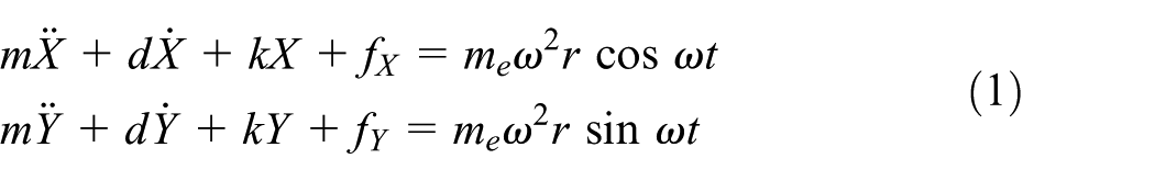


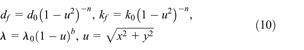
where m, d, and k are the rotor-generalized (modal) mass, lateral external damping, and lateral isotropic stiffness coefficients, respectively. me and r are the eccentric mass and eccentricity of the rotor, respectively. ω is the rotational speed. rf is the radial clearance of the seal. mf, df, and kf are the fluid inertia, fluid film radial damping, and stiffness coefficients in the seal, respectively. λ is the fluid circumferential average velocity ratio. d0, k0, λ0, n, and b are the parameters of the nonlinear seal force. The parameters of the fluid force are described in detail by Muszynska. 2 ma, da, and ka are the mass, damping, and stiffness coefficients of the DVA, respectively. X, Y, Xa, and Ya are the displacements of the rotor and DVA, respectively. The rotor stiffness coefficient k contains the elements of the shaft stiffness ks and the support stiffness kb


(a) The seal force model (left) and (b) the rotor/seal system with the DVA model (right).
The nondimensional transform is as follows
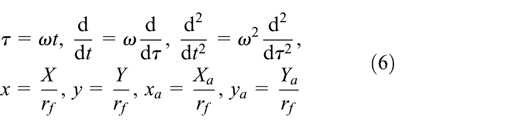

Substituting equations (6) and (7) into equations (1)–(4), the original equations become the nondimensional equations


where

Nonlinear dynamic characteristics of the rotor/seal-DVA system
Newmark time integration method 39 is used to solute the complicated nonlinear equations. The algorithm is unconditionally convergent as the values of parameters β ≥ 1/4 and γ ≥ 1/2. 40 The bifurcation diagrams, waterfall diagrams, frequency spectrums, rotor orbits, and Poincaré maps are used to illustrate the nonlinear dynamic behaviors of the rotor/seal-DVA system.
The parameters of the rotor/seal system are as follows. The rotor mass m = 1 kg, the natural frequency ωr = 200 rad/s, and the damping ratio ζr = 0.025. The radial clearance of the seal rf = 10−3 m and the eccentricity ratio εe = 0.01. The fluid inertia ratio εf = 1×10⁻⁶ and other parameters d0 = 100 N m/s, k0 = 1 N/m, λ0 = 0.48, n = 2, and b = 0.5. It is known that the “cross-stiffness” terms (±ωλdf) in equation (2) are the most important factors affecting the rotor nonlinear behaviors and stability. The nonlinear behaviors of the real rotor/seal system can be described by the above-mentioned parameters.
The parameters of the DVA are considered as follows. Picking the mass ratio ε = 0.01 since the DVA mass ratio is limited for the practical considerations. It is known that the fluid-induced vibration frequency is almost equal to the natural frequency of the rotor, so picking the natural frequency of the DVA ωa = ωr. Normally, the damping ratio is relatively small, so picking the damping ratio ζa = 0.01. The influences of the natural frequency and damping ratio are discussed in the next section.
The bifurcation and waterfall diagrams in the x-coordinate of the rotor/seal system without the DVA are established and the results are shown in Figure 3. The rotational speed ω as a bifurcation parameter is considered. f is the rotor vibration response frequency. Assuming the nondimensional rotational speed s = ω/ωr, Figure 3(a) shows that the response is the synchronous vibration when s < 2.31, and the instability vibration due to the nonlinear seal force appears when s ≥ 2.31. s = 2.31 is the instability threshold of the rotor/seal system. The instability vibration frequency is close to the natural frequency ωr of the rotor, and the amplitude of the instability vibration is much higher than that of the synchronous vibration as shown in Figure 3(b). The rotational frequency ω and the combination frequency ω – 2ωr exist in the waterfall diagram besides the instability frequency ωr, and the amplitude of the combination frequency ω – 2ωr is much smaller than that of the rotational frequency ω. The combination frequency appears with the instability frequency.
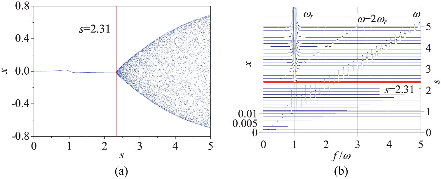
(a) The bifurcation (left) and (b) waterfall (right) diagrams of the rotor/seal system without the DVA in the x-coordinate.
Figures 4 and 5 show the synchronous and instability vibrations for s = 1.5 and s = 2.605, respectively. Figure 4 shows that the rotational frequency ω only exists in the frequency spectrum, the orbit of the rotor is a regular circle, and an isolated point is in the Poincaré section. Figure 5 represents that the rotational frequency ω, the natural frequency ωr of the rotor, and the combination frequency ω – 2ωr exist in the frequency spectrum; the orbit of the rotor is irregular; and a closed curve formed by the infinite points is in the Poincaré section. It is a quasi-periodic response.
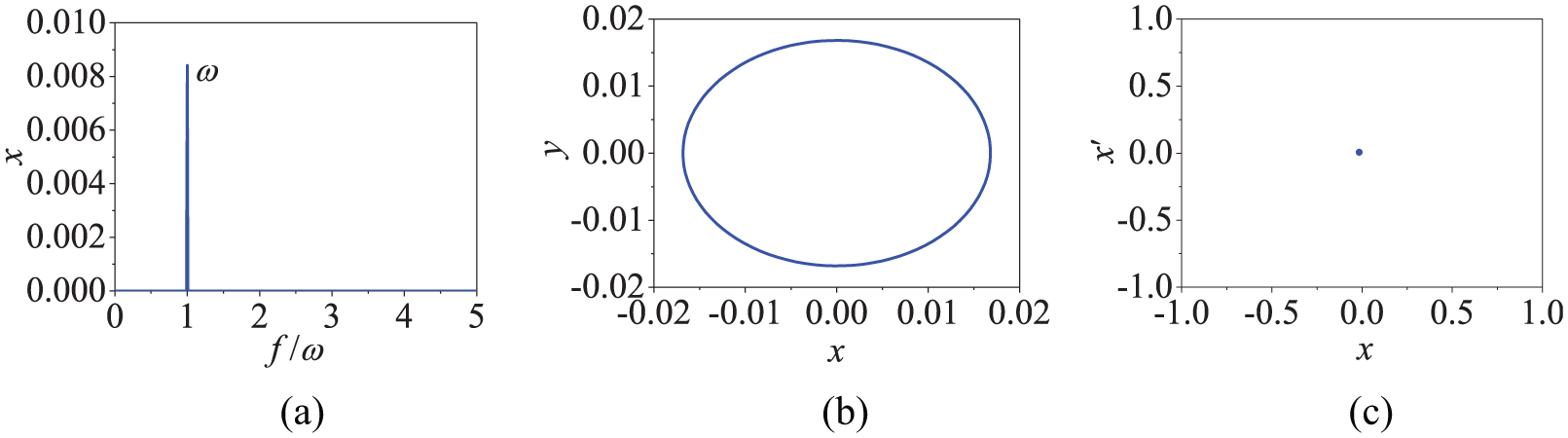
The synchronous vibration of the rotor/seal system at s = 1.5. (a) The frequency spectrum of the x-coordinate (left),(b) the orbit of the rotor (middle) and (c) the Poincaré map of the x-coordinate (right).

The instability vibration of the rotor/seal system at s = 2.605. (a) The frequency spectrum of the x-coordinate (left),(b) the orbit of the rotor (middle) and (c) the Poincaré map of the x-coordinate (right).
The bifurcation and waterfall diagrams in the x-coordinate of the rotor/seal system with the DVA are established and the results are shown in Figure 6. Figure 6(a) shows that the response is the synchronous vibration when s < 2.265, and the instability vibration due to the nonlinear seal force appears when s ≥ 2.265. s = 2.265 is the instability threshold of the rotor/seal-DVA system. Figure 6(b) and (c) shows that the instability vibration frequency is close to the first-order natural frequencies ωn1 of the rotor-DVA system as the rotational speed s is between 2.265 and 3.795, and the amplitude of the instability vibration is much higher than that of the synchronous vibration. In this case, the rotational frequency ω and the combination frequency ω – 2ωn1 exist in the waterfall diagram besides the instability frequency ωn1, and the amplitude of the combination frequency ω – 2ωn1 is much smaller than that of the rotational frequency ω. The combination frequency ω – 2ωn1 appears with the instability frequency ωn1. The instability vibration frequency is close to the second-order natural frequencies ωn2 of the rotor-DVA system as the rotational speed s exceeds 3.795, and the amplitude of the instability vibration is much higher than that of the synchronous vibration. In this case, the rotational frequency ω and the combination frequency ω – 2ωn2 exist in the waterfall diagram besides the instability frequency ωn2 and the amplitude of the combination frequency ω – 2ωn2 is much smaller than that of the rotational frequency ω. The combination frequency ω – 2ωn2 appears with the instability frequency ωn2.

(a) The bifurcation diagram (upper left), (b) the waterfall diagram at view 1 (upper right), and (c) waterfall diagram at view 2 (lower middle) of the rotor/seal system with the DVA in the x-coordinate.
Figures 7–9 show the synchronous and instability vibrations for s = 1.5, s = 3.5, and s = 4.11, respectively. Figure 7 shows that the rotational frequency ω only exists in the frequency spectrum, the orbit of the rotor is a regular circle, and an isolated point is in the Poincaré section. Figure 8 represents that the rotational frequency ω, the first-order natural frequency ωn1 of the rotor-DVA system, and the combination frequency ω – 2ωn1 exist in the frequency spectrum; the orbit of the rotor is irregular; and a closed curve formed by the infinite points is in the Poincaré section. It is also a quasi-periodic response. Figure 9 represents that the rotational frequency ω, the second-order natural frequency ωn2 of the rotor-DVA system, and the combination frequency ω – 2ωn2 exist in the frequency spectrum; the orbit of the rotor is irregular; and a closed curve formed by the infinite points is in the Poincaré section. It is also a quasi-periodic response.

The synchronous vibration of the rotor/seal-DVA system at s = 1.5. (a) The frequency spectrum of the x-coordinate (left), (b) the orbit of the rotor (middle), and (c) the Poincaré map of the x-coordinate (right).

The instability vibration of the rotor/seal-DVA system at s = 3.5. (a) The frequency spectrum of the x-coordinate (left), (b) the orbit of the rotor (middle), and (c) the Poincaré map of the x-coordinate (right).

The instability vibration of the rotor/seal-DVA system at s = 4.11. (a) The frequency spectrum of the x-coordinate (left), (b) the orbit of the rotor (middle), and (c) the Poincaré map of the x-coordinate (right).
Compared with the nonlinear dynamic characteristics between the rotor/seal system without and with the DVA, it can be seen that (1) the instability threshold of the rotor/seal system becomes smaller by attaching the DVA as shown in the bifurcation diagrams in Figures 3(a) and 6(a), that is, the instability threshold of the rotor/seal system can be changed by the DVA. (2) Only one instability frequency is in the waterfall diagram in Figure 3(b) in the rotor/seal system. However, two instability frequencies are in the waterfall diagrams in Figure 6(b) and (c) in the rotor/seal system with the DVA. The two frequencies do not appear at the same time. The first-order natural frequency appears first, and then, the second-order natural frequency appears, while the first-order natural frequency disappears. The combination frequencies appear or disappear with the instability frequencies. (3) The type of the vibration does not change by the DVA as shown in the frequency spectrums, rotor orbits, and Poincaré maps in Figures 4, 5, and 7 –9. The synchronous and instability vibrations still exist in the rotor/seal system with the DVA. The effects of the parameters of the DVA on the nonlinear dynamic characteristics of the rotor/seal system are discussed as follows.
Influences of the parameters of the DVA on the nonlinear dynamic characteristics of the rotor/seal system
The DVA consists of the mass, stiffness, and damping elements. The mass ratio is limited for the practical considerations, so the natural frequency (stiffness element) and damping ratio (damping element) are analyzed for the dynamic behavior of the rotor/seal-DVA system in this section.
The effects of the natural frequency of the DVA on the nonlinear dynamic characteristics in the rotor/seal system with the DVA are presented as follows. Assume the nondimensional natural frequency σa =ωa/ωr. Figure 10 indicates the bifurcation and waterfall diagrams in the x-coordinate of the rotor/seal system with the DVA when σa =0.8. Figure 10(a) shows that the response is the synchronous vibration when s < 2.335, and the instability vibration due to the nonlinear seal force appears when s ≥ 2.335. s = 2.335 is the instability threshold of the rotor/seal-DVA system. The instability vibration frequency is close to the second-order natural frequency ωn2 of the rotor-DVA system, and the amplitude of the instability vibration is much higher than that of the synchronous vibration as shown in Figure 10(b). The rotational frequency ω and the combination frequency ω – 2ωn2 exist in the waterfall diagram besides the instability frequency ωn2, and the amplitude of the combination frequency ω – 2ωn2 is much smaller than that of the rotational frequency ω. The combination frequency ω – 2ωn2 appears with the instability frequency ωn2.
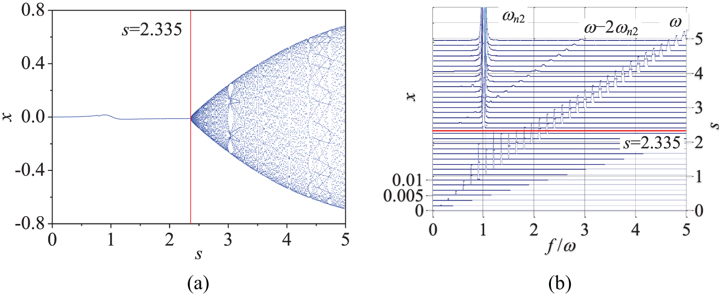
(a) The bifurcation (left) and (b) waterfall (right) diagrams of the rotor/seal system with the DVA in the x-coordinate when σa = 0.8.
Figure 11 indicates the bifurcation and waterfall diagrams in the x-coordinate of the rotor/seal system with the DVA when σa = 0.9. The variations in the nonlinear dynamic characteristics in Figure 11 are the same as in Figure 10. Only the value of the instability threshold is different. s = 2.365 is the instability threshold of the system.

(a) The bifurcation (left) and (b) waterfall (right) diagrams of the rotor/seal system with the DVA in the x-coordinate when σa = 0.9.
Figure 12 indicates the bifurcation and waterfall diagrams in the x-coordinate of the rotor/seal system with the DVA when σa =1.1. Compared with Figure 11, the instability vibration frequency becomes close to the first-order natural frequency ωn1 instead of the second-order natural frequency ωn2 of the rotor-DVA system. Correspondingly, the combination frequency becomes ω – 2ωn1. s = 2.265 is the instability threshold of the rotor/seal-DVA system.

(a) The bifurcation (left) and (b) waterfall (right) diagrams of the rotor/seal system with the DVA in the x-coordinate when σa = 1.1.
Figure 13 indicates the bifurcation and waterfall diagrams in the x-coordinate of the rotor/seal system with the DVA when σa = 1.2. The variations in the nonlinear dynamic characteristics in Figure 13 are the same as in Figure 12. Only the value of the instability threshold is different. s = 2.28 is the instability threshold of the system.

(a) The bifurcation (left) and (b) waterfall (right) diagrams of the rotor/seal system with the DVA in the x-coordinate when σa = 1.2.
Compared with the bifurcation diagrams in Figures 6(a), 10(a), 11(a), 12(a), and 13(a), it can be seen that the natural frequency of the DVA has an effect on the instability threshold of the rotor/seal system. The instability threshold increases first, then decreases, and increases again (2.335 → 2.365 → 2.265 → 2.265 → 2.28) as the natural frequency of the DVA increases (0.8 → 0.9 → 1 → 1.1 → 1.2). The instability threshold is maximum when σa = 0.9. Compared with the waterfall diagrams in Figures 6(b) and (c), 10(b), 11(b), 12(b), and 13(b), it can be seen that the natural frequency of the DVA has an effect on the instability frequency. The instability frequency is the first-order natural frequency of the rotor-DVA system when σa = 1.1 and σa = 1.2. However, the instability frequency is the second-order natural frequency of the rotor-DVA system when σa = 0.8 and σa = 0.9. The instability frequency is the first-order natural frequency of the rotor-DVA system when the instability vibration appears, and then, the instability frequency becomes the second-order natural frequency of the rotor-DVA system as the rotational speed increases when σa = 1. The combination frequency changes accordingly with the instability frequency.
The effects of the damping ratio of the DVA on the nonlinear dynamic characteristics in the rotor/seal system with DVA are considered as follows. Figure 14 indicates the bifurcation and waterfall diagrams in the x-coordinate of the rotor/seal system with the DVA when ζa = 0.02. The variations in the nonlinear dynamic characteristics in Figure 14 are the same as in Figure 6. Only the values of the instability threshold and the rotational speed at which the instability frequencies occur are different. s = 2.34 is the instability threshold of the system. The instability vibration frequency is close to the first-order natural frequency ωn1 of the rotor-DVA system as the rotational speed s is between 2.34 and 3.69. The instability vibration frequency is close to the second-order natural frequency ωn2 of the rotor-DVA system as the rotational speed s exceeds 3.69.
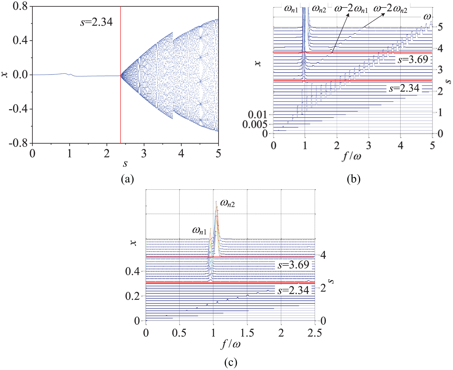
(a) The bifurcation diagram (upper left), (b) the waterfall diagram at view 1 (upper right), and (c) waterfall diagram at view 2 (lower middle) of the rotor/seal system with the DVA in the x-coordinate when ζa = 0.02.
Figure 15 indicates the bifurcation and waterfall diagrams in the x-coordinate of the rotor/seal system with the DVA when ζa = 0.03. The variations in the nonlinear dynamic characteristics in Figure 15 are the same as in Figure 14. Only the values of the instability threshold and the rotational speed at which the instability frequencies occur are different. s = 2.425 is the instability threshold of the system. The instability vibration frequency is close to the first-order natural frequency ωn1 of the rotor-DVA system as the rotational speed s is between 2.425 and 3.92. The instability vibration frequency is close to the second-order natural frequency ωn2 of the rotor-DVA system as the rotational speed s exceeds 3.92.

(a) The bifurcation diagram (upper left), (b) the waterfall diagram at view 1 (upper right), and (c) waterfall diagram at view 2 (lower middle) of the rotor/seal system with the DVA in the x-coordinate when ζa = 0.03.
Figure 16 indicates the bifurcation and waterfall diagrams in the x-coordinate of the rotor/seal system with the DVA when ζa = 0.04. Compared with Figure 15, the instability vibration frequency becomes close to the first-order natural frequency ωn1 instead of the first- and second-order natural frequencies ωn1 and ωn2 of the rotor-DVA system. Correspondingly, the combination frequency becomes ω – 2ωn1. s = 2.505 is the instability threshold of the rotor/seal-DVA system.
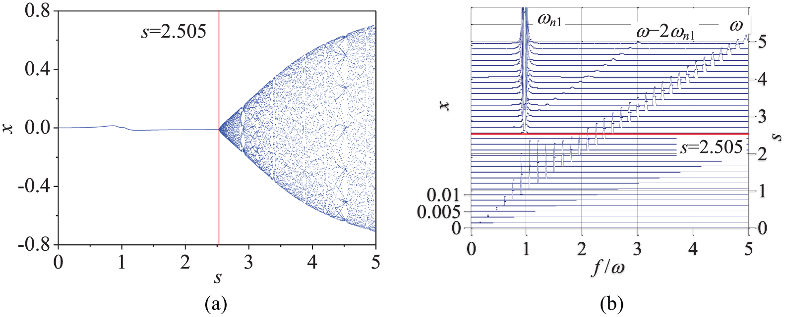
(a) The bifurcation (left) and (b) waterfall (right) diagrams of the rotor/seal system with the DVA in the x-coordinate when ζa = 0.04.
Figure 17 indicates the bifurcation and waterfall diagrams in the x-coordinate of the rotor/seal system with the DVA when ζa = 0.05. Compared with Figure 16, the instability vibration frequency becomes close to the natural frequency ωr of the rotor instead of the first-order natural frequency ωn1 of the rotor-DVA system. Correspondingly, the combination frequency becomes ω–2ωr. s = 2.58 is the instability threshold of the rotor/seal-DVA system.
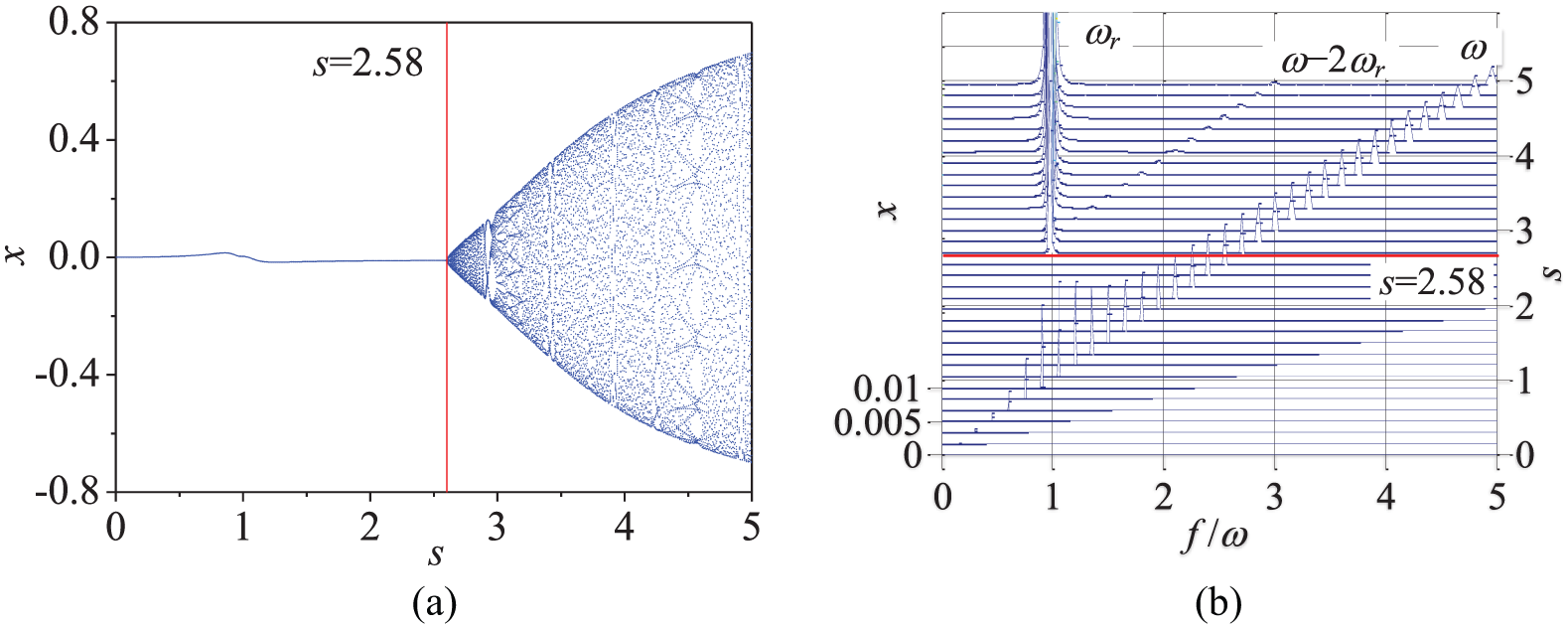
(a) The bifurcation (left) and (b) waterfall (right) diagrams of the rotor/seal system with the DVA in the x-coordinate when ζa = 0.05.
Figure 18 indicates the bifurcation and waterfall diagrams in the x-coordinate of the rotor/seal system with the DVA when ζa = 0.06. The variations in the nonlinear dynamic characteristics in Figure 18 are the same as in Figure 17. Only the values of the instability threshold and instability frequency are different. s = 2.605 is the instability threshold of the system.

(a) The bifurcation (left) and (b) waterfall (right) diagrams of the rotor/seal system with the DVA in the x-coordinate when ζa = 0.06.
Compared with the bifurcation diagrams in Figures 6(a), 14(a) 15(a), 16(a), 17(a), and 18(a), it can be seen that the damping ratio of the DVA has an effect on the instability threshold of the rotor/seal system. The instability threshold increases (2.265 → 2.34 → 2.425 → 2.505 → 2.58 → 2.605) as the damping ratio of the DVA increases (0.01 → 0.02 → 0.03 → 0.04 → 0.05 → 0.06). The instability threshold is maximum when ζa = 0.06. Compared with the waterfall diagrams in Figures 6(b) and (c), 14(b) and (c), 15(b) and (c), 16(b), 17(b), and 18(b), it can be seen that the damping ratio of the DVA has an effect on the value of the instability frequency. Two instability frequencies ωn1 and ωn2 are in the waterfall diagrams in the rotor/seal system with the DVA when ζa = 0.01, ζa = 0.02, and ζa = 0.03. However, only one instability frequency ωn1 is in the waterfall diagrams in the rotor/seal system when ζa = 0.04. Then, as the damping ratio continues to increase, the instability frequency becomes close to the rotor natural frequency ωr when ζa = 0.05 and ζa = 0.06.
The effects of the DVA on the nonlinear dynamic characteristics in the rotor/seal system are listed as shown in Table 1. It can be seen that the instability frequency is the first-order natural frequency of the rotor-DVA system when the natural frequency of the DVA is larger than that of the rotor. The instability frequency is the second-order natural frequency of the rotor-DVA system when the natural frequency of the DVA is smaller than that of the rotor. In the case of the rotor natural frequency is equal to the DVA natural frequency, the instability frequency is the first-order natural frequency of the rotor-DVA system, and then, it becomes the second-order natural frequency as the rotational speed increases when the damping ratio is smaller. The instability frequency becomes the rotor natural frequency again as the damping ratio continues to increase. The variations in the instability threshold are discussed in detail in the following section.
The effects of the DVA on the nonlinear dynamic characteristics in the rotor/seal system.

DVA: dynamic vibration absorber.
Stability of the rotor/seal-DVA system
The natural frequency and damping ratio of the DVA can influence the instability threshold of the rotor/seal system based on the above analysis. Therefore, the stability region of the rotor/seal system will be extended to higher rotational speeds possibly, that is, the appearance of the instability vibration will be postponed possibly using the DVA. In this section, the effects of the DVA on the stability of the rotor/seal system are discussed.
Equations (1)–(4) are linearized for the stability analysis by the eigenvalue theory. The nonlinear terms and the fluid inertia coefficient in equations (1)–(4) are neglected as they are minimal and the unbalance force is assumed to be zero.2,16 The nonlinear model becomes a classical linear model

where

The solutions for equation (11) are as follows

where A and Aa are the integration constants and μ is the complex eigenvalue.
Substituting solutions (13) into equation (11), the complex characteristic equation is provided
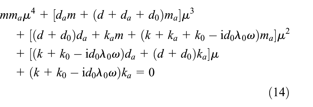
The complex eigenvalue can be obtained by equation (14). The response of the system is stable when the eigenvalue has negative real part. The response is at the threshold of instability when the real part of the eigenvalue equals to zero. The vibration is unstable when the eigenvalue has positive real part.
The instability threshold of the rotor/seal system with the DVA is presented in Figures 19 and 20. The red and black solid lines represent the instability threshold of the rotor/seal system without and with the DVA, respectively. Figure 19 illustrates the effect of the natural frequency of the DVA on the instability threshold. The instability threshold of the rotor/seal system with the DVA is smaller first, then larger, and again smaller than that of the rotor/seal system without the DVA as σa increases. Figure 19(a) shows that the instability threshold of the rotor/seal system with the DVA is smaller than that of the rotor/seal system without the DVA in the range of σa (0.01, 0.75) and (0.96, 2), respectively. The instability threshold of the rotor/seal system with the DVA is larger than that of the rotor/seal system without the DVA in the range of σa (0.75, 0.96). s = 2.37 is the maximum of the instability threshold at σa =0.93 when ζa = 0.01. The variations in the instability threshold in Figures 19(b)–(h) are the same as in Figure 19(a). Only the values of the instability threshold are different. The range of σa that the instability threshold of the rotor/seal system with the DVA is larger than that of the rotor/seal system without the DVA varies with the damping ratio ζa. The upper limit of the range increases (0.96 → 1.01 → 1.04 → 1.07 → 1.08 → 1.1 → 1.11 → 1.13) and the lower limit of the range decreases (0.75 → 0.73 → 0.71 → 0.69 → 0.68 → 0.66 → 0.64 → 0.63) as ζa increases (0.01 → 0.02 → … → 0.08). However, the maximum of the instability threshold increases first and then decreases (2.37 → 2.46 → 2.51 → 2.65 → 2.67 → 2.63 → 2.58 → 2.54) as ζa increases. s = 2.67 is the maximum of the instability threshold at σa = 0.99 when ζa = 0.05.

The stability diagrams of the rotor/seal system with the DVA when the natural frequency of the DVA changes.

The stability diagrams of the rotor/seal system with the DVA when the damping ratio of the DVA changes.
Figure 20 illustrates the effect of the damping ratio of the DVA on the instability threshold. Figure 20(a)–(e) shows that the instability threshold of the rotor/seal system with the DVA is smaller first, then larger, and again smaller than that of the rotor/seal system without the DVA as ζa increases. Figure 20(a) shows that the instability threshold of the rotor/seal system with the DVA is smaller than that of the rotor/seal system without the DVA in the range of ζa (0.01, 0.03) and (0.98, 1), respectively. The instability threshold of the rotor/seal system with the DVA is larger than that of the rotor/seal system without the DVA in the range of σa (0.03, 0.98). s = 2.33 is the maximum of the instability threshold at ζa = 0.28 when σa =0.7. The variations in the instability threshold in Figure 20(b)–(e) are the same as in Figure 20(a). Only the values of the instability threshold are different. Figure 20(a–f) shows that the range of ζa that the instability threshold of the rotor/seal system with the DVA is larger than that of the rotor/seal system without the DVA varies with the natural frequency ratio σa. The upper limit of the range decreases until 0.26 (0.98 → 0.87 → 0.78 → 0.68 → 0.57 → 0.26) and the lower limit of the range decreases first and then increases until 0.26 (0.03 → 0+ → 0+ → 0.02 → 0.06 → 0.26) as σa increases (0.7 → 0.8 → … → 1.2). The maximum of the instability threshold increases first and then decreases (2.33 → 2.35 → 2.41 → 2.58 → 2.34 → 2.31) as σa increases. s = 2.58 is the maximum of the instability threshold at ζa = 0.05 when σa =1. Figure 20(f) shows that the maximum of the instability threshold of the rotor/seal system with the DVA is equal to that of the rotor/seal system without the DVA, and others of the rotor/seal system with the DVA are smaller than that of the rotor/seal system without the DVA when σa = 1.2. Figure 20(g) and (h) shows that the instability threshold of the rotor/seal system with the DVA is smaller than that of the rotor/seal system without the DVA when σa =1.3 and σa = 1.4.
Conclusion
The effects of the DVA on the nonlinear dynamic behavior and stability of the fluid-induced vibration instability in the rotor/seal system are investigated in this article. The 4-degree-of-freedom isotropic rotor/seal system with the DVA model is established. Newmark time integration method is used to solve the differential equations. The effects of the natural frequency and damping ratio of the DVA on the dynamic characteristics of the fluid-induced vibration in rotor/seal system are discussed. The complex characteristic equation is provided for the stability analysis. The effects of the DVA on the stability region of the fluid-induced vibration in the rotor/seal system are obtained. Some conclusions are as follows:
The type of the dynamic response of the rotor/seal system is not changed by the DVA. The synchronous and instability vibrations still exist in the rotor/seal system with the DVA.
The instability vibration frequency of the rotor/seal system is changed by the DVA. The instability frequency is changed from the rotor natural frequency to the first- or second-order natural frequency of the rotor-DVA system.
The instability threshold of the rotor/seal system is changed by the DVA. The instability threshold is decreased by the DVA in some parameter ranges, and the instability vibration will occur at a lower rotational speed when the DVA is used to attenuate the critical or unbalanced vibration of the rotor. This result must be avoided.
Footnotes
Handling Editor: Elsa de Sa Caetano
Declaration of conflicting interests
The author(s) declared no potential conflicts of interest with respect to the research, authorship, and/or publication of this article.
Funding
The author(s) disclosed receipt of the following financial support for the research, authorship, and/or publication of this article: This study was financially supported by the National Natural Science Foundation of China (grant nos 51475085 and U1708257) and 2017 Higher Education Institution Basic Research Project of Liaoning Province (grant no. LQGD2017019).