
Abstract
To standardize the reliability test evaluation schedule of passenger cars powertrain, a multi-condition varying-speed accelerated test criteria correlated with the statistical data of target vehicles is developed. With this test criteria, a real-vehicle test is conducted to evaluate a trial-manufacture car equipped with a newly developed transmission. Regarding the fracture failure of the driving and driven gears of the final drive, a heat treatment quality inspection is conducted on the fractured gears. From the meshing state of the gears, it is observed that machining precision errors caused an excessively large bearing clearance of the helical gear in the differential housing, with the meshing area of the driving gear tilting to one side and generating eccentric loads under uneven stress. The fatigue damage of the gears is calculated by the rainflow cycle matrix of the gears obtained with the rotating rainflow counting method. The calculation results show that largest loads transmitted by the final drive gears in varying-speed test condition 2, which was the main condition for fractures of the driven gear. Under this condition, the driving gear also produced bending fatigue failure due to the significant-amplitude cyclic loading caused by the eccentric loads.
Keywords
Introduction
Due to the change in gears position of automotive transmission, the torque and rotational speed transmitted by its working gears are often in a changing state, and the gear will cause alternating loads, so fatigue fracture is the most common failure mode of automotive transmissions.1–3 Fatigue is a local damage process of components and parts produced by cyclic loading. The rainflow counting method can be applied to process the load-time history into a rainflow cycle counting matrix of amplitude-mean-cycles.4,5 During cyclic loading, local plastic deformation will occur in the highest stress zone, which will induce fatigue damage of parts and components.6–8 The automotive propshaft system is responsible for transmitting the power generated by the engine to the wheels. During this period, such parts as the transmission gears, bearing, and differential housing often produce fatigue failure due to the change of transmission torque amplitude, with the improvement of vehicle technology and the increase of vehicle speed, transmission work under worse conditions, accompanied by the ever-increasing fatigue failures.9,10 Among the broken parts and components, the gear failure accounts for about 60%, the bearing failure for about 19%, and the gear shafts failure for about 10%. 10 In most cases, the transmission is subjected to dynamic loads that change over time, which are generally random functions of time. The research results of fatigue damage of automotive transmission gears show that the bending moment of the gear tooth is linear with the torque of the input shaft, and the number of cycles of the driving gear is also linear with the number of revolutions of the input shaft.1,3 In a rotation period of a gear, only the gear in meshing state is stressed, so the load on a tooth of the gears is pulse load.2,3 The dedendum is susceptible to bending fatigue failure when subjected to alternating bending stress that exceeds the fatigue limit of the gear material, and the macroscopic manifestations of gear failure may include fatigue fractures traversing the dedendum of a whole gear tooth and the localized fractures or cracks of the dedendum, which usually occur in transmission gears or final drive gears that endure greater bending stress.7–9 Additionally, repetitive high contact stress on the tooth surface may cause localized metal peeling and then contact fatigue damage to the tooth surface, which can be shown as pitting peeling, shallow peeling, and hardening layer peeling. 10 The final drive of a car is part of the transmission assembly, which is damaged due to the fractured teeth of the driving helical gear initially and ultimately destroyed by the failure of the driven helical gear. In fact, the vehicle varying-speed accelerated test is a gear shift enhancement test, mainly aiming to assess and evaluate the reliability and durability of powertrain, and moreover, it refers to a series of tests needed to examine the design level and technology reasonability before design, development, and type approval for the parts and components of the transmission systems. Efforts are usually made to test and verify machined prototypes and improve the product design and technology level, so as to timely expose potential problems before product marketing and enhance the reliability of products.11–13 The design of modern automobile must be market-oriented, and the products with “too long” or “insufficient” design life are usually uneconomical and lack of market competitiveness, so the actual use requirements of customers should be considered in the automobile design, development, or test stage.14–17 Assessing the reliability of products during the product development cycle is an important task in satisfying customers. Severity of usage is the prime factor affecting field reliability.1,3,9 The engineer must be knowledgeable of usage severity and incorporate this factor into the product design. The primary role of reliability testing is to measure the reliability of a component or system released to the conformance to customer requirements.18–20 To ensure that customer expectations are fully addressed, product development specifications must require that products provide reliable performance over the entire customer ownership period. Verification of design conformance to customer-driven specifications is a key step within a prevention methodology development program. Reliability testing is the only practical means to verify that products meet life and functional specifications.1,3,21,22
In this paper, first it is necessary to develop a multi-condition varying-speed accelerated test criteria for passenger cars that is correlated with the target vehicles statistics. Then, the newly developed transmission should be assembled in a vehicle for testing and verification. Meanwhile, need to measure the torque and rotational speed of the automotive propshaft and the vehicle speed, and calculate the fatigue damage caused by the varying-speed accelerated test to the driving and driven gears of the final drive. Finally, based on the calculation results of the fatigue damage in the varying-speed test, the fracture failure mechanism of the final drive gears should be analyzed by taking into account both the testing of the heat treatment quality of materials used for the driving and driven gears of the final drive and the gears meshing state.
Development of varying-speed accelerated test criteria
Failure model of 90% target vehicle
In the study of automotive reliability engineering, the wear life, fatigue life, fatigue strength, corrosion life of engineering materials, as well as automotive assemblies composed of many units, generally obey the Weibull distribution.1,3 In the test data processing of the reliability of automotive components, unless it is sure that it belongs to a certain distribution, the Weibull distribution is generally used to count the life of automotive components. Due to the presence of three undetermined parameters in the Weibull probability density function, it can better fit the experimental data points. For the roads of target vehicle and the high-speed loop road of the Proving Ground, the fatigue damage of the propshaft torque obeys Weibull distribution, its cumulative function is defined as

Where F(t) is the cumulative distribution function, t is the fatigue damage of propshaft torque, β is the scale parameter, and m is the shape parameter. The Weibull distribution parameters can be estimated through the least squares method, and equation (1) can be rewritten as

In probability paper of Weibull distribution, if X = ln t is set as the x-coordinate and Y = ln[−ln(1−F(t))] as the y-coordinate. Equation (2) can be written into a linear equation as

Therefore, the least squares method estimation results of Weibull distribution parameters are expressed by

According to the statistical data of target vehicles and the linear equation (3), the mathematical model for the fatigue damage of automotive propshaft torque with a failure probability of 90% on real roads actually is given as
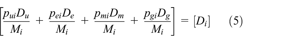
For n target vehicles, the equation (5) is transformed into a matrix equation as follows

Where M i is the vehicle loading adjustment factor, p ui , p ei , p mi , and p gi represent the percentages of city roads, expressways, hilly roads, and public roads, respectively. D u , D e , D m , and D g denote the 90% target vehicle accumulated damage of city roads, expressways, hilly roads, and public roads, respectively. D i is the total accumulated damage of the i-th 90% target vehicle, n is the total number of samples of target vehicles.
Accumulated damage simulation
Aiming at the total fatigue damage of 90% target vehicle, a normal distribution statistical model is established, so that the solution is exactly the mathematical expectation of the statistical probability model.23,24 The total fatigue damage calculated by equation (6) obeys a normal distribution, and a random sampling model following the normal distribution can be established for simulation. Two groups of independent random numbers r1 and r2 evenly distributed on (0, 1) are generated by RAND( ) function.
According to Monte Carlo simulation method, for any normally distributed random variable x i , if its mean is μ and variance is σ 2 , it can be obtained through the following transformation.

Hence, the simulation error of Monte Carlo is

For a given significance level α, t α can be solved by looking up the value of standard normal distribution function, so the Monte Carlo simulation error is decided by the variance and the number of sampling times. Random samples following a normal distribution were generated through the sampling method based on the transformation of equation (7), and the accumulated fatigue damage of 90% target vehicle was solved through simulation and sampling. The more simulation calculations are performed, the closer the mean value of the statistic is to the true value.
Test data acquisition
The torque-revolutions distribution of automotive propshaft is an interval counting method for shaft and gear of rotating components, which has been widely used in the design and analysis of gear trains. The analysis flowchart is shown in Figure 1. In order to create the loading spectrum of torque-revolutions distribution, it is necessary to simultaneously obtain the torque and rotational speed signals of the input shaft. According to the torque versus number of revolutions histogram, the discontinuous time intervals (Δt i , i = 1, 2, 3 …m) in the rotational speed time history (rpm(t)) is known, and the number of revolutions (n i ) of the rotating shaft under the given torque T i is calculated, expressed as follows
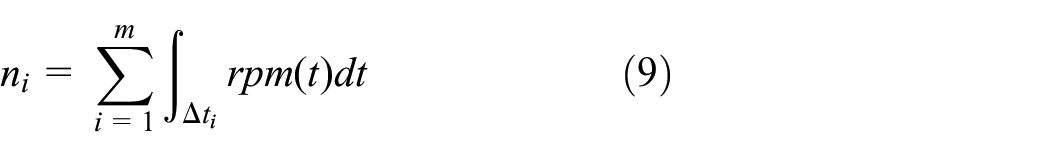

Generation approach of number of revolutions.
As the main component of automotive powertrain, the output torque of propshaft is an important measurement parameter in the varying-speed accelerated test. Specifically, the CAEMAX single channel non-contact torque telemeter is used to measure the torque of the automotive propshaft, as shown in Figure 2, the rig test for the torque calibration is presented in Figure 3, and the measuring system of the torque is shown in Figure 4, the real vehicle assembly of data acquisition instrument is shown in Figure 5.

Non-contact torque telemeter.

Rig test calibration of propshaft torque.

Measuring system of propshaft torque.
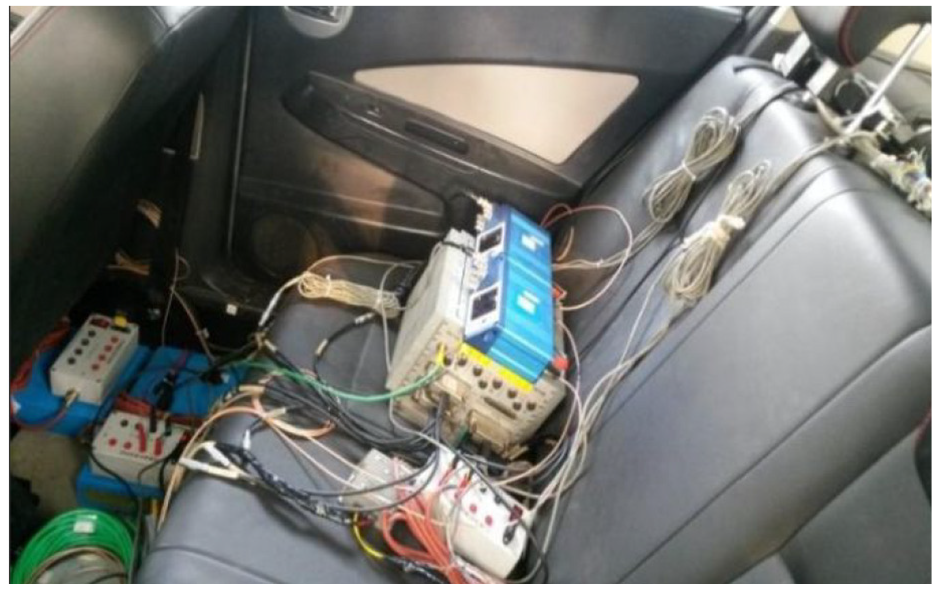
Test data acquisition instrument.
Among the many mathematical models to describe progressive and accumulated damage, a linear damage rule has been widely accepted by practicing engineers because of its simplicity, despite its shortcomings of unpredictability and the exclusion of the load-sequence effect. Therefore, the linear accumulated damage of torque versus rotational speed can be expressed as
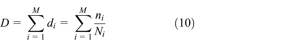
The summation notion represents the accumulation of each individual damage (d i ), which is defined by the ratio of n i to N i , where n i is the counted number of revolutions at a automotive propshaft torque level T i , and N i is the fatigue life in revolutions to failure at the same torque level determined from a torque versus life (T-N) curve.
In the distribution diagram of torque and rotational speed, the number of revolutions at each torque level can be determined by the paired interval counting algorithm. The fatigue resistance curves for the baseline fatigue torque of the automotive propshaft and the number of revolutions at which fatigue takes place can be given as

Where T i is the torque of propshaft, T f is the fatigue strength coefficient, b is the fatigue strength exponent.
Using the number of revolutions n i counted under one torque T i and combining equations (9)–(11), the fatigue life N i and damage d i of each interval can be obtained.
When the engine outputs a specific torque, according to a given discrete time interval in the time history of rotational speed, the number of revolutions of the automotive propshaft can be counted. On the premise of ignoring the transmission gear efficiency, the torque and revolutions of the driving shaft of the final drive can be approximately expressed as


Where T I is the torque of the driving shaft of the final drive; T P is the torque of the driven shaft of the final drive, REV I is the total number of revolutions of the driving shaft of the final drive, REV P is the total number of revolutions of the driven shaft of the final drive, and G0 is the final drive gears ratio.
Using the ranking and estimated the probability of the fatigue damage caused by the automotive propshaft torque, by using the least squares estimation method, the parameter values of the Weibull distribution can be obtained, as shown in Table 1. Using the linear equation (3) fitted by the Weibull probability paper, the calculated accumulated damage of 90% target vehicle on each road is listed in Table 2.
Estimation value for Weibull parameters.

Accumulated damage of 90% target vehicle.
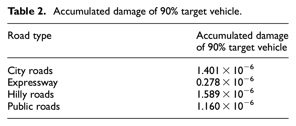
Combined with the statistical percentages of road type for the target vehicles, the fatigue damage of each vehicle was calculated by equation (6). The simulation results of Monte Carlo sampling showed that the accumulated fatigue damage of 90% target vehicle is 1.18 × 10⁻⁶, and the number of simulation sampling times is 10,000. The confidence level is 95% to ensure the simulation algorithm precision of Monte Carlo sampling. At this time, the simulation error is 0.78%.
Varying-speed test schedule
According to the theory of structural fatigue, the fatigue damage of a vehicle powertrain is caused by cyclic loading mainly, if the input loading of the vehicle is same, then the fatigue damage induced in theory also should be same.1,3,19 Calculating the fatigue damage of the automotive propshaft torque in the actual usage environment of the target vehicles, equivalent fatigue damage can be replicated through varying-speed accelerated test in the high-speed loop road of the Proving Ground.3,19 The varying-speed test can usually be completed in a relatively short time, so the purpose of accelerated test of the vehicle powertrain can be achieved.
Figure 6 illustrates the varying-speed test procedures for the transmission system under the three operating conditions, with the notations in the figures representing.
A denotes the engine speed corresponding to its maximum power.
B represents the engine speed corresponding to its maximum torque, which is set to 3500 r/min when it exceeds 3500 r/min.
C is 80% of the engine speed B, which is set to 2800 r/min when the engine speed under the maximum torque exceeds 3500 r/min.
S stands for standardly shift gear; Q stands for quickly shift gear.
D denotes the throttle fully opened; E denotes the throttle fully closed.
V.limit is 90% of the actual maximum speed of the test vehicle. If the speed exceeds 180 km/h, it is set to 180 km/h. If it exceeds the speed limit of the Proving Ground, it is set to the speed limit.

Operating diagram of varying-speed test conditions: (a) operating condition 1, (b) operating condition 2, and (c) operating condition 3.
The measured propshaft torque is classified and counted, and transformed into the number of revolutions or the distribution matrix of revolutions at the different torques level and rotational speeds. The propshaft damage corresponding to all torque levels of each road and each file can be calculated by using the classification counting matrix of propshaft torque, as shown in Figures 7 and 8, and the fatigue damage under three test conditions are shown in Table 3.

Fatigue damage distribution of propshaft torque.

Accumulated damage of propshaft torque.
Statistical value of fatigue damage under three test conditions.

According to the principle of the accumulated damage equivalence resulting from the combined measurement of torque and rotational speed of the automotive propshaft, this paper calculated the fatigue damage induced by 90% target vehicle and through a varying-speed accelerated test on the high-speed loop road of the Proving Ground. The accelerated factor of the varying-speed accelerated test can be given by

Where K is the accelerated factor, d and E a denote the driving distance and fatigue damage of 90% target vehicle, respectively. R and E b represent the total driving distance and fatigue damage on the high-speed loop road of the Proving Ground in a test cycle, respectively.
Based on statistics about the actual usage of the target vehicles, a multi-condition varying-speed accelerated test criteria was developed for the transmission system of the passenger cars. The target life mileage was set to 300,000 km for 90% target vehicle, the accelerated factor calculated from equation (14) is 19.23, corresponding to 15,600 km in the varying-speed test of the transmission system on the high-speed loop road, with a total of 230 test cycles. During the testing, the driver fulfilled one test cycle by operating under condition 1, condition 2, and condition 3 sequentially as required, and continued until finishing all the 230 test cycles.
Fatigue failure of gears in varying-speed test
Test data verification
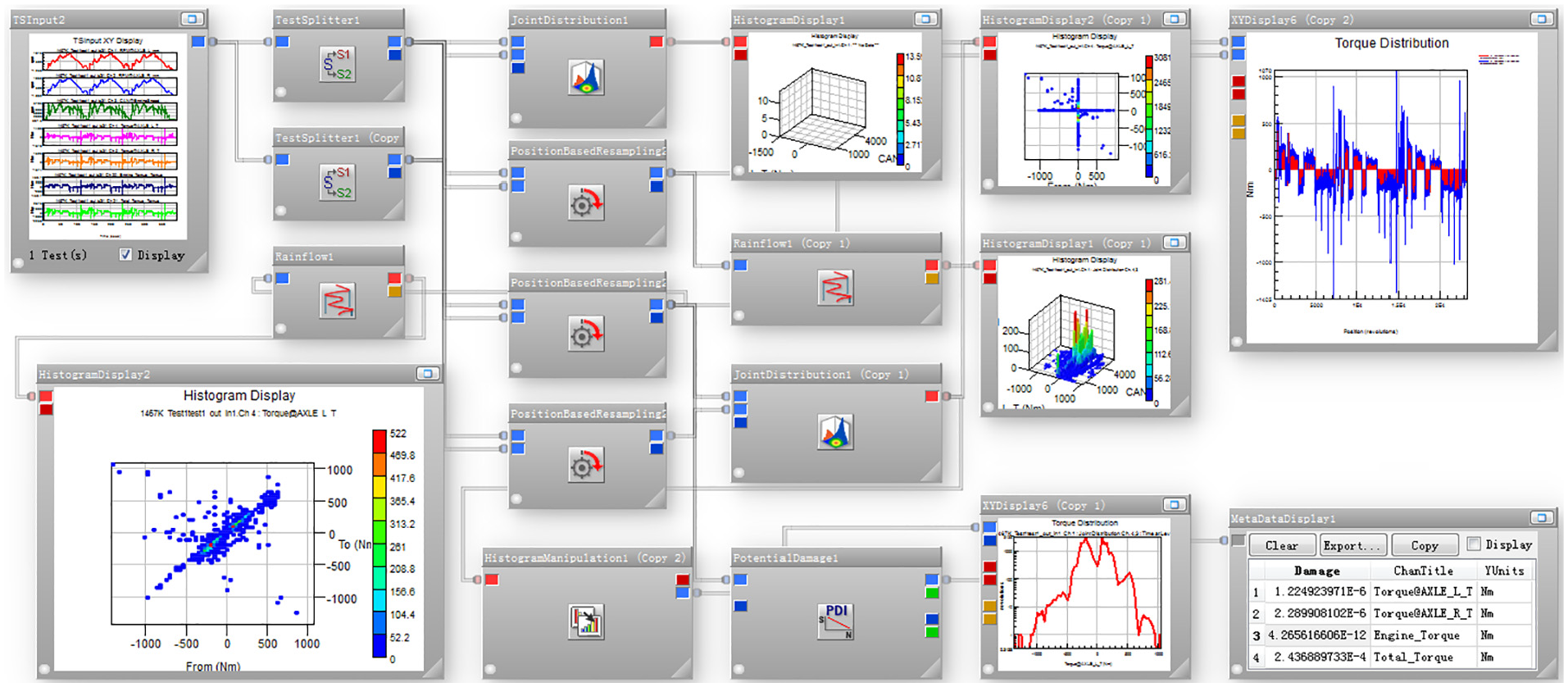
Due to the influence of environmental temperature, magnetic field interference, and the sensor itself, some of the original data collected in the test have some problems such as zero-line drift, spike, and trend, so the data must be preprocessed. A data processing model for experiments was established using Glyph works, as shown in Figure 9. By using this model, the torque and speed of the automotive propshaft under three varying-speed test conditions were converted into the torque and rotational speed of the driving shaft of the final drive, as shown in Figure 10. The statistical results of test data regarding the torque of the driving shaft of the final drive under three varying-speed test conditions are listed in Table 4.

Preprocessing model of varying-speed test data.

Torque and rotational speed of driving shaft under three test conditions: (a) varying-speed test condition 1, (b) varying-speed test condition 2, and (c) varying-speed test condition 3.
Statistical value of driving shaft torque.

Analyzing and comparing the test data under three varying-speed accelerated test conditions, except the varying-speed impact torque, the amplitude of other torques ranged from −100 to 100 Nm under conditions 1 and 3, while the negative torque amplitude under condition 2 is equivalent to that under conditions 1 and 3, and the positive torque amplitude is kept near 140 Nm, which already exceeded the maximum output torque 135 Nm of the engine. This large-amplitude alternating torque load would cause great fatigue damage to the driving shaft gear of the final drive.
Calculation of fatigue damage
The rotating rainflow counting method is different from the general rainflow counting method of stress and strain signals. Usually, under the action of a steady torque, the shaft will not be subjected to fatigue damage in case of no alternating load. For teeth, any tooth will be subjected to a load every time the shaft rotates. When the shaft rotates continuously, the teeth will be subjected to the cyclic loading, so the teeth will go through accumulated fatigue damage. 1 Rotating rainflow counts an implicit load history of a reference tooth into a “tooth matrix,” the implicit load history is formed from torque and rotational speed history, a shaft matrix is counted via conventional rainflow from the torque signal alone. The total matrix is built up as the sum of “tooth matrix” and “shaft matrix.” Cycles originating from revolutions have one anchor point at zero torque. The form a visible cross within the “tooth matrix.” In each completed revolution the “reference tooth” touches its counterpart once. Only then it experiences the applied torque. The tooth load is calculated by creating a turning point sequence connecting zero load with torque level, using the frequency defined by the corresponding RPM (Revolutions Per Minute) value.
The fatigue damage calculation flowchart of shaft and teeth is shown in Figure 11. To calculate the fatigue damage of driving shaft gear teeth, it is necessary to establish the damage calculation model of shaft and teeth by using the rotating rainflow counting method, as shown in Figure 12.

Damage calculation flowchart of shaft and teeth: (a) fatigue damage of shaft and (b) fatigue damage of teeth.
Fatigue damage calculation model of shaft and teeth.
When the propshaft rotates, the gears on the shaft generate continuous torque, so the torque transmitted by the shaft is the outer envelope line of the torque borne by all teeth, as shown in Figure 13. The torque of the driving shaft of the final drive is subjected to interval counting and transformed into a revolutions matrix at different torques and rotational speeds, as shown in Figure 14. Figure 15 presented the rotating rainflow matrix corresponding to the teeth.

Rotating rainflow counting process of shaft and teeth.
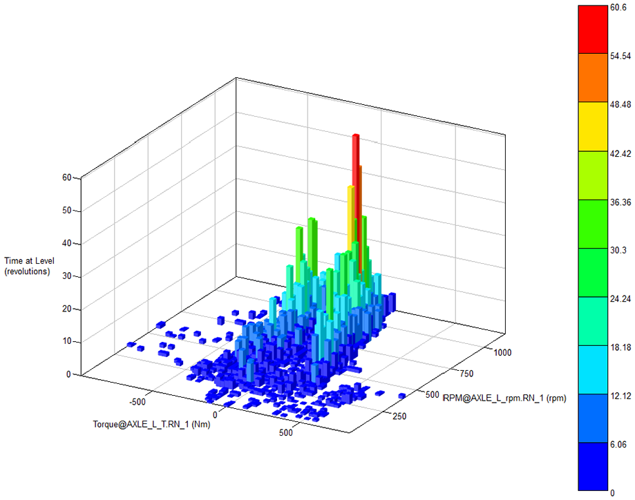
Counting matrix of torque and rotational speed.

Rotating rainflow matrix of teeth.
The fatigue damage distribution under three varying-speed accelerated test conditions is shown in Figure 16. It could be seen that the damage value caused by the negative torque in the varying-speed test is equivalent without evident differences. The maximum damage value generated by positive torque under condition 2 is 4.43 × 10⁻¹⁰, which is much greater than that under conditions 1 and 3. Table 5 shows the comparison of the damage under three varying-speed test conditions. The accumulated damage in a single test cycle under condition 2 is 42.5 × 10⁻¹⁰. Figure 17 shows the accumulated damage of the driving shaft gear of final drive under condition 2. When the torque value is between −170 and 100 Nm, the accumulated damage value is approximate to the horizontal line, and the damage generated is minor. In this case, the automotive propshaft is subjected to the large-amplitude “anti-dragging” impact torque loading from the ground and resulting in larger accumulated fatigue damage, indicating that condition 2 is the main condition leading to the gear failure of the driving shaft of the final drive.

Fatigue damage of driving gear teeth under three test conditions: (a) varying-speed test condition 1, (b) varying-speed test condition 2, and (c) varying-speed test condition 3.
Damage comparation under three varying-speed test conditions.


Accumulated damage of driving gear teeth under test condition 2.
Failure mechanism analysis of gears
The machining precision of gears has a significant impact on fatigue performance. Under alternating loads, defects such as surface roughness, scratches, and cracks on gear teeth can easily cause stress concentration and produce fatigue cracks. 25 The rougher surface, the lower fatigue strength. When the texture of the processed surface is perpendicular to the force direction, the fatigue strength decreases significantly. To enhance the surface hardness and wear resistance of the gears, it is necessary to reduce the machining precision errors to ensure the surface finish of the components. 26
During the varying-speed testing, the final drive gears that fractured and failed include the driving and driven gears. Both the driving and driven gears are helical gears, which have undergone heat treatment by carburizing and quenching. The driving gear is made of 20MnCr5, with its blank processed by cold extrusion. The detected surface hardness is HV716; the hardness of the dedendum core at half of tooth thickness is HV403; the effective hardening layer depth of the tooth surface at half of tooth thickness is 0.51 mm. The blank of the driven gear made of 16MnCr5 was processed by isothermal normalizing after hot die forging. The detected surface hardness of the gear is HV694; the hardness of the dedendum core at half of tooth thickness is HV387; the effective hardening layer depth of the tooth surface at half of tooth thickness is 0.42 mm. After heat treatment, the driving and driven gears were processed by intense shot peening to improve their fatigue strength. The metallographic testing results show that the surface layer of the fractured gear is tempered martensite, uniformly distributed fine-grained carbides, and a small amount of residual austenite, while the core is low-carbon martensite and a small amount of ferrite. The inspection results of the heat treatment of the fractured gears showed that the metallographic structure, surface hardness, and core hardness of the gears all met the required technical parameters, but the effective hardening layer depth did not conform to the standard technical parameters for design (The design value is 0.80–1.0 mm).
From the perspective of gear meshing, the meshing area of the driving gear tilted toward one side of teeth, with obvious marks of eccentric loading as shown in Figure 18. The lower part of the pitch circle of the driving gear is evidently worn, with marks of tooth damage at the dedendum and obvious interference, as shown in Figure 19. The fracture mode of the driving gear of the final drive is due to fatigue failure. It was mainly because the eccentric loads led to bending cyclic loading during the varying-speed test and finally the failure of the gears, the form of which demonstrated sensitivity to large loads. As illustrated in Figure 20, the driven gear with relatively thin teeth and a shallower effective hardening layer depth suffered brittle fractures under high-amplitude impact loading during the varying-speed accelerated test.

Eccentric meshing of driving shaft gear.

Worn dedendum of driving shaft gear.

Fracture morphology of driven shaft gear.
Conclusions
Based on the principle of fatigue damage equivalence, this study developed a multi-condition varying-speed accelerated test criteria for passenger cars correlated with the target vehicles statistics, which standardized the accelerated test schedule of vehicle powertrain and avoided the blindness of the previous reliability test.
With data acquired from the multi-condition varying-speed accelerated test of a real vehicle, a torque damage calculation model was built for the driving gear of the final drive by using Glyph Works. The fatigue damage of the driving gear was calculated and analyzed, the results of which showed that condition 2 of the varying-speed accelerated test was a primary test condition for gear fractures with the most significant effect in the fatigue damage of the driving and driven gears.
Due to machining precision errors, the bearing clearance of the helical gears in the differential housing was so large that the meshing area of the driving gear shifted toward one side and led to cyclic eccentric loading under uneven stress during the varying-speed accelerated test, which is the primary cause of the failure of the driving gear. Compared with the driving gear, the driven gear with a shallower effective hardened layer depth and thinner teeth suffered fatigue failure under the high-amplitude cyclic impact loading during the varying-speed test. The research findings of this paper could provide an important basis for the subsequent structural design and technological improvement of the final drives.
Footnotes
Handling Editor: Jesus Felez
Declaration of conflicting interests
The author(s) declared no potential conflicts of interest with respect to the research, authorship, and/or publication of this article.
Funding
The author(s) disclosed receipt of the following financial support for the research, authorship, and/or publication of this article: This work was supported by the Talent Introduction Research Initiation Fund Project of Suqian University (Suqian University No. 2023XRC020), and Science and Technology Development Project of Jilin Province (No. 20210101064JC).