
Abstract
Electric power steering control faces several issues related to state errors, sensor noise, and chattering. This article proposes an adaptive robust control method based on a sliding mode control mechanism to address the existing drawbacks. The sliding surface of this controller is adjusted dynamically by a fuzzy technique, which is formed by two inputs and one output. The system disturbances and state variables are estimated by an extended state observer instead of being measured by expensive sensors. Combining the above techniques is a new contribution to the article to improve the system’s control performance. Numerical simulations are performed in three cases with varying driver torque and velocity. The computational results reveal that the output signals of the system controlled by the proposed method closely track the desired values, with errors not exceeding 1.5% (except for the assisted current). The observed error of the system disturbance does not exceed 12.172%, while the observed error of the remaining state variables is less than 3%. Overall, the performance of the proposed algorithm is significantly improved compared with the traditional control methods.
Keywords
Introduction
An electric power steering (EPS) system is critical to modern vehicles. Replacing traditional Hydraulic Power Steering (HPS) systems with EPS systems helps reduce the system’s weight and size. 1 This was confirmed in the study of Amirkhani et al. 2 Park et al. made a comparison to evaluate the fuel consumption between EPS and HPS. The results in Park et al. 3 showed that the fuel efficiency of modern EPS systems was improved compared to other traditional systems. In addition, the EPS system provides fast response speed and adaptability in various operating conditions. However, some problems related to the steering system’s inertia and noise persist. 4
Several studies on EPS control applications have been published recently. Guan et al. 5 designed a Proportional-Integral-Derivative (PID) controller to calculate the ideal values for the steering system. They used the MATLAB PID toolbox to determine the control parameters. Hassan et al. utilized a Genetic Algorithm (GA) to tune the ideal parameters for PID control based on minimizing the objective function, that is, making the Root Mean Square (RMS) error converge to zero. 6 However, this work was presented simply and needed more scientific evidence. Hanifah et al. 7 proposed the use of Ant Colony Optimization (ACO) and Particle Swarm Optimization (PSO) algorithms to find the ideal parameters for the PID controller. The calculation results in Hanifah et al. 7 illustrated that the Mean Square Error (MSE) converged after about 15 iterations. However, the energy efficiency was only slightly improved compared to conventional PID. A Back Propagation Neural Network (BPNN) mechanism for tuning PID parameters was introduced by Li et al. 8 The MSE value converged after about 36 epochs. However, the performance of this controller depended on the vehicle’s speed. An Adaptive Neuro Fuzzy Inference System (ANFIS) for EPS system control was introduced by Ramos-Fernández et al. 9 The training data were collected from a conventional PD controller. The simulation results in Ramos-Fernández et al. 9 confirmed that the training error was significant which was caused by the performance degradation in the PD controller. Zheng and Wei proposed a fuzzy PI technique to control the automotive EPS system to improve the system’s performance. The calculation data in Zheng and Wei 10 showed that the state error was significantly declined while the overshoot phenomenon still existed, although its influence was average. An integrated PID-PI control scheme was presented by Manca et al. 11 The performance of this algorithm was severely degraded under high-frequency excitation signals. To solve the problem related to power limitations for large commercial vehicles, Fu et al. proposed a dual-power EPS system controlled by three PI controllers. 12 A major limitation in Fu et al. 12 is calculating optimal control values.
The PID controller is only suitable for Single Input and Single Output (SISO) systems. Regarding systems with Multiple Input and Multi Output (MIMO), PID control should be replaced by a Linear Quadratic Regulator (LQR). Chitu et al. 13 designed an LQR controller to control the performance of the EPS system. The objective of this method was to minimize a quadratic cost function. Liu et al. utilized the GA to improve the performance of the LQR controller, considering sensor failures. 14 Irmer and Henrichfreise proposed a Linear Quadratic Gaussian algorithm for steering system control based on combining LQR and an observer. However, the observer error was quite large. 15 The LQR control technique requires knowledge of the system output signals. Using sensors to measure these signals directly may lead to increased sensor noise. A Kalman filter was fitted to estimate the measurement states and noise, following Mehrabi et al. 16
The above two control techniques are only suitable for simple linear systems. A Sliding Mode Control (SMC) mechanism was introduced in Nguyen 17 to control the EPS system and improve its performance. However, taking the higher derivative of the output signal could negatively impact the system’s performance. Kim et al. 18 designed a sliding mode controller with a disturbance observer to control an automobile’s steering system. The lack of algorithm presentation was a major limitation. Kim et al. presented an SMC mechanism based on an Extended State Observer (ESO) for steering wheel torque tracking. 19 The calculation results showed that the chattering phenomenon affected the output signal. Another SMC control method was introduced by Khasawneh and Das. 20 The Lyapunov criterion evaluated the stability of the system. However, the effects of chattering and phase shifting remained. Another study proposed by Lee et al. showed that the steering wheel speed and acceleration were strongly affected by chattering, which was considered a characteristic phenomenon of the SMC framework. 21 This was due to incorrect sliding surface selection. Some other control applications for EPS systems should be referred to References 22–26.
Although the above control methods provide stable performance in system control, some drawbacks still exist. Firstly, the state error is significant in some investigated cases.6,9,11 Secondly, sensor noise continues to influence and degrade the signal quality.15,16,27 Finally, the impact of chattering remains unresolved.18–21 In this work, we propose to design an adaptive, robust control algorithm to solve the above issues. The proposed algorithm combines an SMC mechanism with a soft computing method. The sliding mode controller’s sliding surface is adjusted by the dynamic fuzzy algorithm designed based on unique fuzzy rules to increase adaptability and reduce the influence of chattering. The output state variables and system disturbances are estimated by an ESO instead of measured by sensors. This brings hope for eliminating the influence of sensor noise and reducing system costs. This combination is considered a new contribution to the article to solve the existing issues. The algorithm proposed in this work provides superior adaptability through sliding surface tuning compared to our previous studies.17,22,24,26–30 The influence of sensor noise and disturbances is also expected to be significantly reduced for the algorithm configured based on the SMC mechanism. Several studies on sliding mode control based on state-dependent disturbance have recently been published.31,32 In general, the efficiency of these methods is remarkable, but the algorithmic structure is relatively complex.
The content of the article is structured into four sections. The literature review and new contributions are presented in the Introduction section. Then, the mathematical model of the EPS system and the control algorithm are presented in the following section. The numerical calculation and simulation results are discussed in the third section. Finally, the Conclusion section gives comments and directions for future development.
Mathematical models
This section introduces the mathematical model of the control system.
EPS models
The saturated linear curves in Figure 1 represent the ideal power steering characteristics. The assisted torque (Ta) depends on the driver torque (Td) and vehicle speed (v). The relationship between them is described in (1). If Td is too small, the electric motor will not operate, that is, Ta is zero. Ta increases linearly with Td, reaching saturation if Td exceeds Td_max. The variation of Ta with Td change can be found in equation (2), where bi represents the empirical coefficients. Looking at this figure more closely, one can see that the assisted torque will reduce sharply as the vehicle speed rises, and vice versa. This is intended to improve safety when traveling at high speeds. 28 A quadratic characteristic curve model was presented by Li et al. 33 Another type of curve that depended on many parameters was shown by Guan et al. 34 Li et al. recently proposed an assisted torque lookup method using a multi-map. 35 In general, the characteristic curve shapes in different studies are different and depend on the researchers’ perspectives.


Ideal assisted map.
The structure of an EPS system is shown in Figure 2(a), which consists of a steering wheel, a steering column, a rack and pinion, an electronic control module, an electric motor, and sensors. The relationship between the steering column angle (φc) and steering motor angle (φm) is represented by equations (3)–(5), where Jc is the inertia moment of the steering column, Bc is steering column damping, Kc is steering column stiffness, G is the motor gear ratio, Kt is the steering motor torque coefficient, im is the motor current, Tr is road disturbances, rp is the pinion radius, Lm is the steering motor inductance, Rm is the steering motor resistance, and u(t) is the control signal.


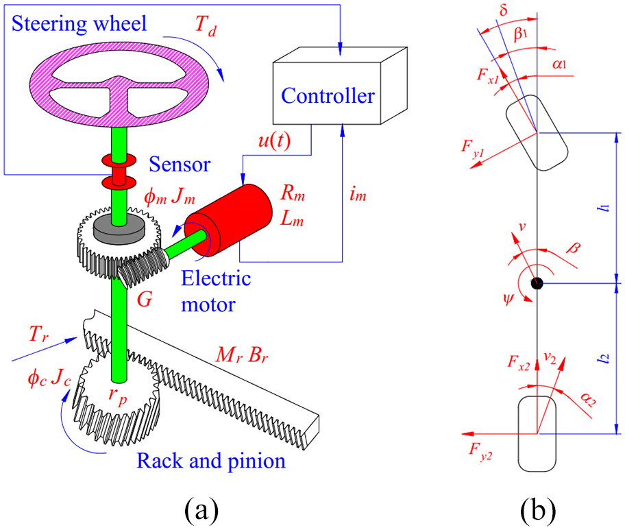
System models: (a) EPS model and (b) vehicle model.
Equivalent moment of inertia (Jeq) and equivalent damping (Beq) are calculated according to (6) and (7), respectively, where Jm is the inertia moment of the steering motor, Mr is rack mass, and Br is rack damping.
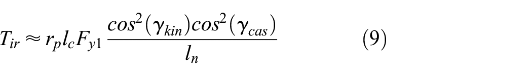
Road disturbances (Tr) are composed of two components, including internal disturbances (Tir) and external disturbances (Ter), according to (8). While the steering process causes Tir, Ter is considered to be the influence of the external environment. The change of internal disturbances is determined by equation (9), where lc is caster trail, ln is knuckle arm length, γkin is kingpin angle, γcas is caster angle, l1 is the distance from center to the front axle, and l2 is the distance from center to the rear axle.

Jang et al. presented a more straightforward method of calculating Tr, 36 whereas Murilo et al.’s model did not deal with determining Tr. 37 Some spatial models used to determine system disturbances should be referred to Nguyen.29,30
The variation of lateral tire force (Fy) is determined by a linear dynamic model (Figure 2(b)), which is represented by equations (10)–(12), where m is vehicle mass, vx is longitudinal velocity, vy is lateral velocity, ψ is yaw angle, and δ is steering angle.


Assuming that the steering angle is slight and the vehicle moves at a constant velocity (*), equations (10)–(12) are rewritten in a more compact form in (13) and (14). The relationship between the lateral and longitudinal velocities is represented by the heading angle β in (15).


According to the condition (*), the tire is considered to be deformed linearly. As a result, lateral tire force is calculated according to (16), where Cα is tire cornering stiffness. The change in tire slip angle (α) is calculated according to (17).


Equations (8)–(17) are utilized to calculate the variation of Tr. The simulation parameters are listed in Table 1.
Vehicle specifications.

Control algorithm
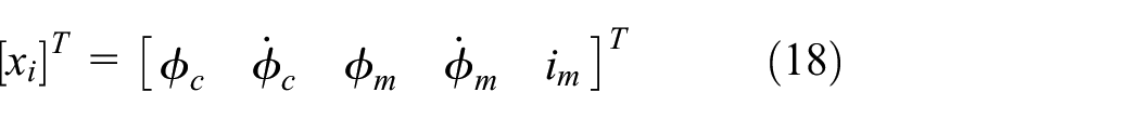
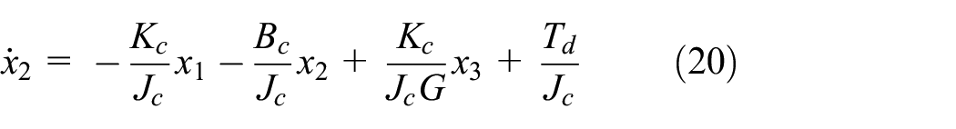
In this article, we introduce to design a control algorithm based on an SMC mechanism to control the performance of the EPS system. Let the state variables be as (18). Equations (19)–(23) are obtained by taking the derivatives of the state variables.


Extended state observer
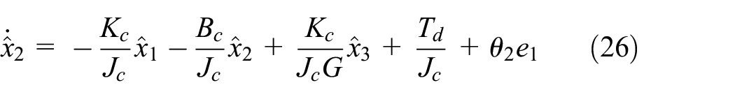
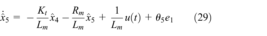
An ESO is established to estimate the changes in state variables instead of measuring them directly with expensive sensors to eliminate the influence of sensor noise and reduce the system cost. According to (24), the changes in road disturbances are estimated by this method through an augmented variable (x6). The mathematical model of the ESO is represented by equations (25)–(30), where e1 is the error between the observed signal and the sensor-measured signal, determined according to (31) and θi are observed gains. The structure and signal flow of the ESO is illustrated in Figure 3.
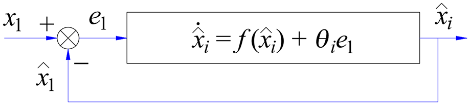
ESO structure and signal flow.
Observed gains (θi) are selected by the pole assignment method to ensure the stability of the observer. This method is performed in three steps. Firstly, the characteristic equation of the observer needs to be established. Then, the desired characteristic equation must be determined. Finally, the observed gains are found by balancing the coefficients of the above two equations.


The steering motor angle is the object to be controlled, denoted by y, according to (32). Taking the derivative of (32) many times, we obtain (33)–(35).


The coefficients ai in equation (35) are interpreted according to (36)–(41).


The error between the controlled signal and the desired signal is denoted as e3, according to (42). Taking the derivative of (42) many times, we obtain (43).


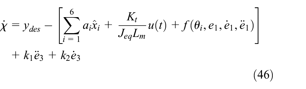
A linear sliding surface (χ) is chosen according to (44), where k1 and k2 are positive constants. Taking the derivative of the sliding surface, we obtain (45).


Combining (35), (43), and (45), we obtain (46).
Stability proofs
Choose the Lyapunov control function according to (47) to satisfy condition (48). Taking the derivative of V(x), we get (49).


The control signal u(t) is chosen as (50), where K is a positive constant. Substituting equations (46) and (50) into (49), we get (51). The derivative of V(x) is negative definite, so the system is theoretically stable. The overall structure of the control system is described in Figure 4.


Control scheme.
While k2 is chosen fixed, k1 is dynamically tuned by the fuzzy algorithm to improve the adaptability of the sliding surface. The input of the fuzzy algorithm is the error of steering column angle (ef1) and steering column speed (ef2), mentioned in (52) and (53), respectively.


The input signals are fuzzified and then computed according to the membership functions mentioned in Figure 5.
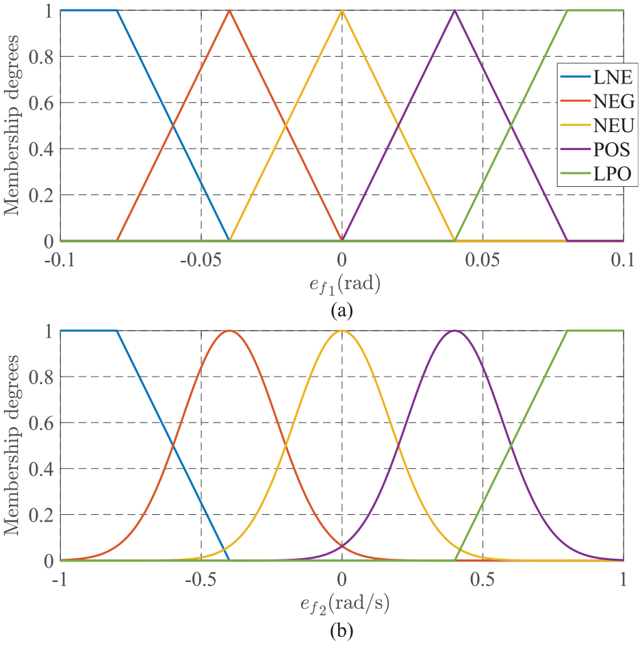
Membership functions: (a) the first input and (b) the second input.
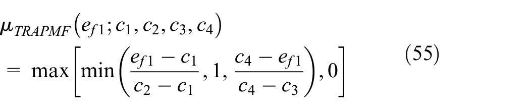
Figure 5(a) provides information about the Triangular Membership Functions (TRIMFs) and Trapezoidal Membership Functions (TRAPMFs) used for the first input. The values of membership degrees are determined according to (54) and (55).


The second input is more sensitive than the first input. Therefore, TRIMFs have been replaced by Gaussian Membership Functions (GAUSSMFs). The membership functions illustrated in Figure 5(b) are explained in (56) and (57), where ci and di are the specific coefficients.
The above membership functions are divided into five levels: Large Negative (LNE), Negative (NEG), Neutral (NEU), Positive (POS), and Large Positive (LPO). A set of fuzzy rules is listed in Table 2. This rule set is formed based on the following remarks:
Fuzzy rule set.

A fuzzy surface illustrates the proposed fuzzy rule to improve visibility (Figure 6).

Fuzzy surface.
Result and discussion
The simulation process is performed to verify the performance of the proposed control method. Two cases corresponding to two different steering signals are investigated (Figure 7(a)). External disturbances are described in Figure 7(b). It is noted that the influence of external disturbances is only considered in the control model, while the ideal model has ignored this.

Input conditions: (a) driver torque and (b) external disturbances.
The system response is investigated at two speeds (v1 = 20 km/h and v2 = 60 km/h). The outputs include steering column angle and speed, steering motor angle and speed, assisted current and torque, and estimated disturbances. The results obtained from the proposed controller (FSMC-ESO) are compared with other control methods (PID-GA and LQR) under the same conditions. The control signal of the PID controller is shown in (58), where kp is a proportional coefficient, ki is an integral coefficient, and kd is a derivative coefficient. These coefficients are determined by the genetic algorithm, which is processed in six stages.
38
In contrast, the control signal of the LQR controller is selected according to (59), where


Simulation input with small driver torque (the first case)
v 1 = 20 km/h
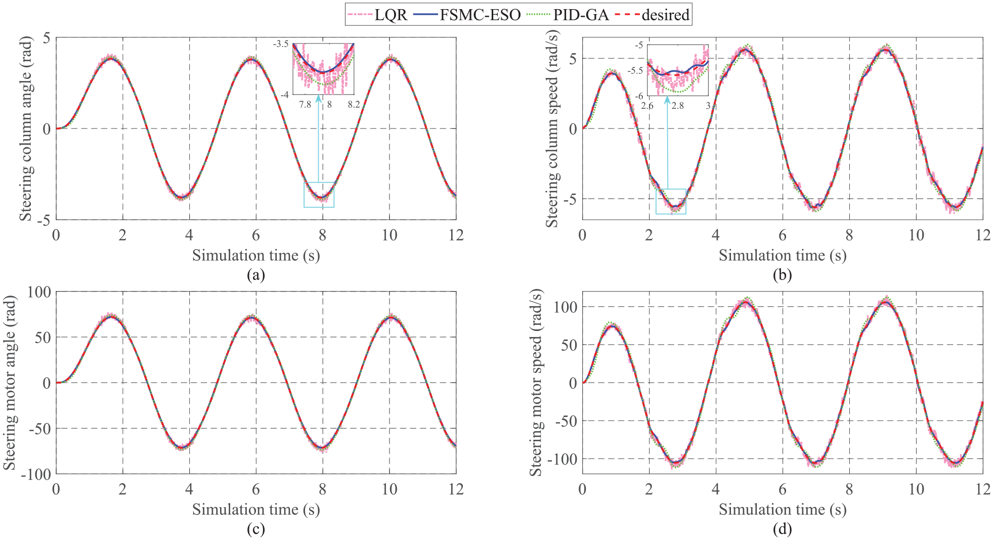
Figure 8 shows the output variation over time when steering at low speed (v1 = 20 km/h). The steering column angle obtained by the three controllers tends to follow the desired signal (Figure 8(a)). The RMS errors of LQR and PID-GA are 2.951% and 3.208%, respectively, while the error obtained by the proposed algorithm is only 0.152%. Looking closely at the window plot, one can see that the signal obtained by PID-GA is slightly overshooting, while the signal obtained by LQR control has to undergo sensor noise. These issues are completely resolved once the proposed technique is utilized to control the steering system.

Simulation outputs (first case, v1): (a) steering column angle, (b) steering column speed, (c) steering motor angle, and (d) steering motor speed.
The curves in Figure 8(b) illustrate the variation of steering column speed. According to this description, the signals obtained from the LQR and PID-GA controllers have significant errors compared to the desired values (6.290% and 7.637%, respectively), while the error belonging to the proposed controller is only 0.824%. In addition, the effects of overshoot and sensor noise are completely eliminated when combining the dynamic fuzzy technique with the SMC based on the ESO mechanism.
Under the control of the FSMC-ESO algorithm, the steering motor angle closely follows the desired signal with a inconsiderable error (0.149%). However, this value increases to 2.922% and 3.204% once the proposed controller is replaced by the LQR and PID-GA controllers, respectively (Figure 8(c)). The change trend in the steering motor speed is similar to that of the steering column speed, but its value is more significant (Figure 8(d)). The simulation results show that the RMS error between the output signal and the desired signal is only 0.723 rad/s (FSMC-ESO), which is much lower than that of the LQR (5.377 rad/s) and PID-GA (8.808 rad/s).
The assisted current characterizes the power steering performance. As shown in Figure 9(a), the current signal generated by the LQR controller is heavily affected by sensor noise. This technique necessitates that the sensors obtain all the information about the state variables through direct measurement. As a result, the signal quality is degraded, leading to an increase in the error up to 40.450%, much higher than that of PID-GA (15.119%). A significant improvement is seen when replacing the traditional controllers with the FSMC-ESO controller, which reduces the RMS error to 6.274%. This provides a significant opportunity to improve the system’s quality and reduce power consumption.
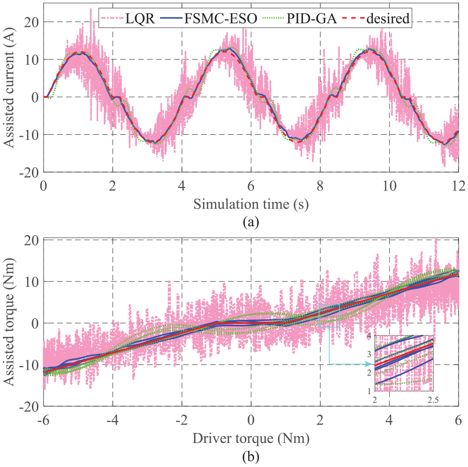
Assisted performance (first case, v1): (a) assisted current and (b) assisted torque.
The dependence of assisted torque on driver torque is illustrated in Figure 9(b). In general, these plots follow the proposed rule in Figure 1. The signal obtained from the FSMC-ESO controller closely tracks the reference signal, while the errors of the LQR and PID-GA are significant. The changes in the state variables are estimated by the ESO instead of being measured directly by the sensor. This helps reduce the system cost and improve the signal quality. The changes in disturbances are determined through the augmented variable (x6) and are illustrated in Figure 10(a). According to the calculation results, the observed signal tends to track the actual signal, with an RMS error of 11.982% and a mean error of 2.296%. This error is caused by the significant influence of external disturbances (high-frequency random signals caused by a white noise source). Under this condition, the observed error is small. According to the article’s findings, the RMS error of the state variables does not exceed 1% (Figure 10(b)), which shows the accuracy in estimating the signals using the ESO.

Observed results (first case, v1): (a) augmented variable and (b) other state variables.
v 2 = 60 km/h
It is necessary to investigate the changes in the state variables at a higher speed to evaluate the proposed method’s performance accurately. The numerical simulation is performed when the vehicle moves at a speed of v2 = 60 km/h. The changes in output state variables are shown in Figure 11. In general, the output values decrease. This is due to the sharp decrease in power steering performance as speed increases, consistent with the proposed rule in Figure 1. As shown in Figure 10(a), the steering column angle errors obtained from the LQR and PID-GA controllers are 3.137% and 2.722%, respectively, while the FSMC-ESO error is only 0.426%. Regarding the steering column speed (Figure 11(b)), the error obtained by the conventional controllers is quite large (6.079% for LQR and 5.594% for PID-GA). The FSMC-ESO controller performs exceptionally well in reducing the error, bringing the value down to 1.430%. The influence of sensor noise exists in all the results of the LQR control, while the signal obtained from the PID control is slightly overshooting.
Simulation outputs (first case, v2): (a) steering column angle, (b) steering column speed, (c) steering motor angle, and (d) steering motor speed.
As mentioned above, the assisted performance declines as the speed increases, that is, the assisted current and assisted torque decrease. This is confirmed by the subplots in Figure 12. The RMS error increases significantly as the speed increases.

Assisted performance (first case, v2): (a) assisted current and (b) assisted torque.
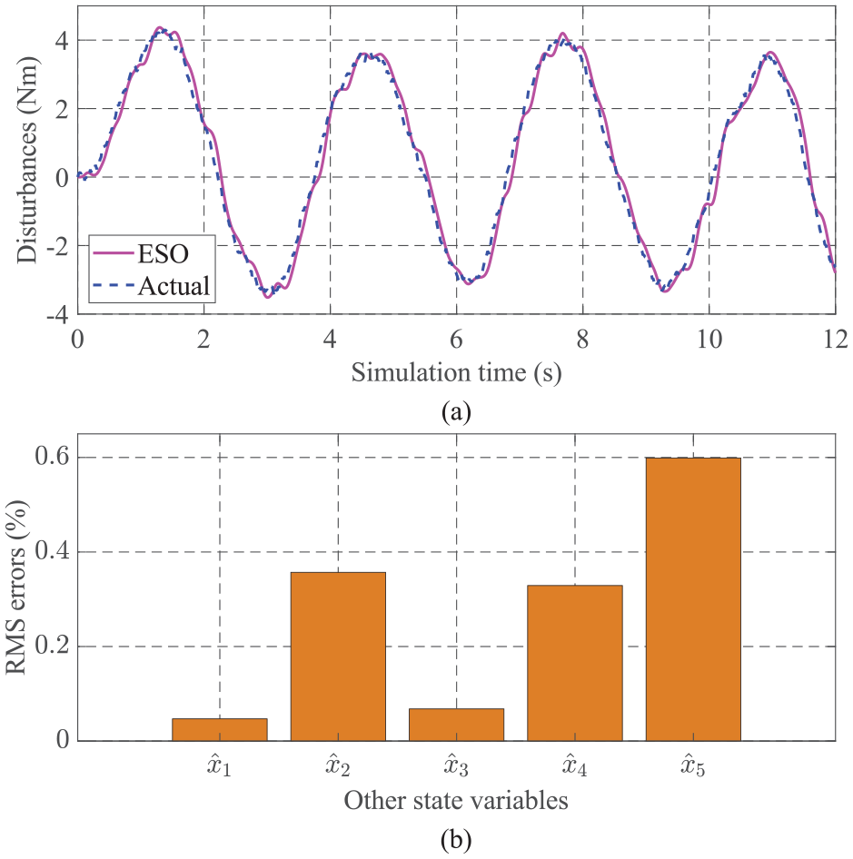
As the vehicle moves at high speeds, the observed error increases. Figure 13(a) shows that the signal observed by the ESO tends to track the actual signal with RMS and mean errors of 9.378% and 3.496%, respectively. Regarding the remaining state variables (Figure 13(b)), the observed error can be as high as 2.588%.

Observed results (first case, v2): (a) augmented variable and (b) other state variables.
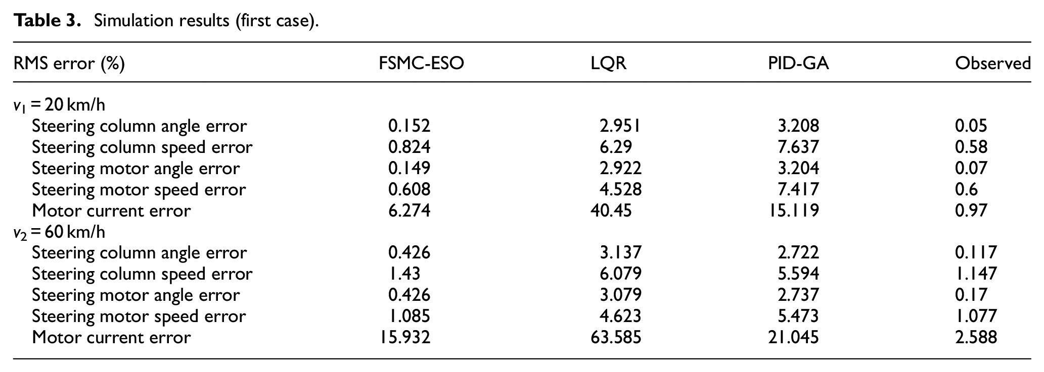
The calculation results in this case are listed in Table 3. One thing to note is that the figures have been rounded after calculation.
Simulation results (first case).
Simulation input with large driver torque (the second case)
The frequency and amplitude of the driver torque signal in this case are more significant than in the first case (Figure 7(a)). The purpose of this is to investigate the saturation characteristics of the system.
v 1 = 20 km/h
The performance of the steering system is strongly promoted when the vehicle is moving at low speed. The calculation results in Figure 14 verify this. The data obtained from the simulation process shows that the RMS error of the steering column angle can be up to 3.001% and 5.559% when applying the LQR and PID-GA controllers to control the system, respectively. However, the state error is significantly reduced to 0.153% when replacing the above conventional controllers with the proposed controller (Figure 14(a)). As depicted in Figure 14(b), the RMS error of the steering column speed obtained by LQR control is about 10 times that of FSMC-ESO, while the error of PID-GA is much larger. The influence of sensor noise (LQR) and overshoot (PID) phenomena is verified by the window plots in Figure 14(a) and (b). The system’s stability is always ensured once the FSMC-ESO technique is utilized to control the steering process. The RMS error between the actual and desired signals does not exceed 0.5% (Figure 14(c) and (d)).

Simulation outputs (second case, v1): (a) steering column angle, (b) steering column speed, (c) steering motor angle, and (d) steering motor speed.
The simulation results in Figure 15 show that the signal obtained from the LQR controller is heavily affected by sensor noise, causing the RMS error of the motor current to increase to 33.061%. Although the error of the PID-GA controller is smaller than that of the LQR (21.577%), it is still a considerable value. In addition, the overshoot phenomenon still exists. A significant improvement is seen when replacing the conventional controller with the FSMC-ESO, causing the state error to drop sharply to 4.048% (Figure 15(a)). The assisted torque characteristic of the proposed controller closely follows the ideal signal. According to Figure 15(b), the value of the assisted torque reaches saturation when the driver torque exceeds its maximum threshold (Td > 8 Nm).

Assisted performance (second case, v1): (a) assisted current and (b) assisted torque.
The observed disturbances’ RMS error increases slightly compared to the first case, while the mean error decreases. The results in Figure 16(a) show that the ESO estimate tends to follow the actual signal. For the remaining state variables, the observed error does not exceed 0.7% (Figure 16(b)).

Observed results (second case, v1): (a) augmented variable and (b) other state variables.
v 2 = 60 km/h
A final investigation is performed when the vehicle is steered at v2 = 60 km/h. Looking at Figure 17, we can see that the output values decrease as the speed increases. A slight overshoot occurs when PID-GA controls the EPS system. Regarding LQR control, the output signals are affected by sensor noise. The above problems are completely solved by applying the adaptive control technique introduced in this article. The simulation results show that the output signals closely track the desired signals with inconsiderable errors (less than 1%) when the FSMC-ESO controller controls the system.

Simulation outputs (second case, v2): (a) steering column angle, (b) steering column speed, (c) steering motor angle, and (d) steering motor speed.
Sensor noise’s effect increases as the car speed rises. As a result, the assisted current’s RMS error increased to 56.096% (LQR control). Although the error of PID-GA is only half that of LQR control, it still causes severe degradation of system performance and increases power consumption (Figure 18(a)). Compared with the two controllers mentioned above, the error obtained by the proposed controller is much lower, only about 10%. In addition, the performance of the proposed algorithm is guaranteed even when the car speed changes, which is verified by the assisted torque curve in Figure 18(b) (FSMC-ESO).

Assisted performance (second case, v2): (a) assisted current and (b) assisted torque.
The simulation results in the final investigation show that the RMS error of observed disturbances is 10.852%. In comparison, the errors of other state variables do not exceed 1%, except for the assisted current (1.936%). These results are described by the subplots in Figure 19.

Observed results (second case, v2): (a) augmented variable and (b) other state variables.
The above simulation results confirmed that the performance of the proposed algorithm is superior to that of the traditional control methods. The error between the actual and desired signals is reduced, and the influence of chattering and sensor noise is eliminated. In addition, the observed errors of the state variables are minor, except for disturbances. Finally, the system response is guaranteed under various investigation conditions.
The simulation data in the second case are given in Table 4.
Simulation results (second case).

Simulation input with heavy disturbances
Another case study is presented in this subsection to verify the controller’s performance under heavy disturbances. The driver torque (Td) in the third case is shown in Figure 20. The amplitude and frequency of the driver torque signal are the same as in the second case (Figure 7(a)). However, this signal is affected by disturbances, causing its value to increase. The external disturbances in this case are similar to the two cases studied previously (Figure 7(b)).

Input with extreme disturbances.
The third case is investigated with a speed of v1 = 20 km/h. The variation of simulation outputs is depicted in Figure 21. Under this condition, the error of the steering column angle is up to 5.670% for PID-GA control and 3.015% for LQR control (Figure 21(a)). The proposed algorithm (FSMC-ESO) provides high efficiency in controlling the system, which reduces the RMS error to 0.150%. Looking closely at the window plot in Figure 21(a), one can see that the overshoot phenomenon still exists when the PID controller controls the system. At the same time, the influence of sensor noise caused by the LQR technique is significant. Regarding the steering column speed (Figure 21(b)), the RMS error of the proposed controller is tiny, only 0.443%. Compared with the two previously investigated cases, the steady-state error in this case is significantly reduced even when the disturbances increase.

Simulation outputs (third case, v1): (a) steering column angle, (b) steering column speed, (c) steering motor angle, and (d) steering motor speed.
Under the influence of heavy disturbances in driver torque, steering motor angle, and steering motor speed values increase rapidly (Figure 21(c) and (d)). While the RMS error of PID control is up to 11.746%, the figure achieved by the proposed controller is only 0.338%.
In this case, heavy driver and external torque disturbances significantly impact the system. This causes an increase in power consumption. The simulation results in Figure 22(a) show that the RMS error of LQR control is up to 4.854 A, which is 35.606%. The error of PID control also increased to 24.229%, which is higher than the second case. On the contrary, the system’s stability is always guaranteed when the FSMC-ESO mechanism controls the EPS system. This is verified through the simulation process with an error not exceeding 4%.

Assisted performance (third case, v1): (a) assisted current and (b) assisted torque.
The disturbance of assisted torque, in this case, is significant. The value obtained from the proposed controller follows the ideal value with a small error. On the contrary, the difference in the value of the remaining techniques is quite significant, causing a deterioration in system performance under harsh working conditions (Figure 22(b)).
The accuracy of the observed state variables is almost unchanged compared to the previous cases. Their RMS errors generally do not exceed 0.6% (Figure 23(b)). The mean error of external disturbances is only 1.444%, while the RMS error is 11.306%, a slight decrease compared to the previous cases (Figure 23(a)). Although the disturbances in driver torque increase, the system error obtained by the proposed controller is almost unchanged, even slightly improved. This is due to the increase in the value of driver torque, which is the result of adding heavy disturbances.
Observed results (third case, v1): (a) augmented variable and (b) other state variables.
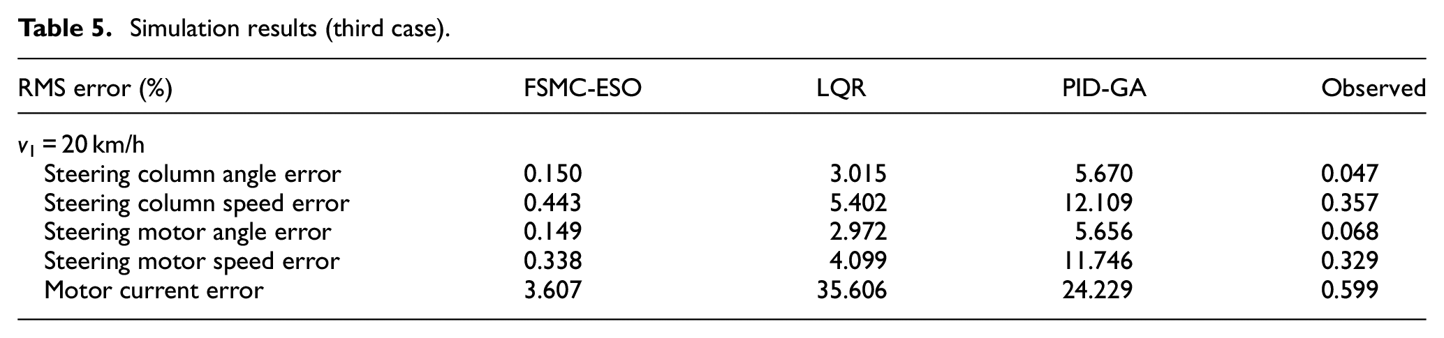
Table 5 provides information on the simulation results obtained in this case.
Simulation results (third case).
Some previous studies have utilized SMC techniques in controller design. As a result, chattering phenomena have emerged, leading to increased RMS error.18−21 In contrast, the results obtained by the algorithm proposed in this work are almost unaffected by chattering, except for the assisted torque in the third case, which is affected by heavy disturbances originating from two sources.
Conclusion
This work proposes a robust nonlinear control mechanism that combines sliding mode control and dynamic fuzzy control to enhance the performance of the EPS system. The extended state observer estimates state variables and system disturbances instead of expensive sensors. Simulations are performed in three cases to investigate the changes in the output variables.
According to the calculation results, the proposed controller’s output signal closely tracks the desired signal with inconsiderable error. In contrast, the RMS error of the conventional controllers is more significant. The observed error is small in the investigated cases. The adaptation and stability of the system are ensured even when the vehicle speed and driver torque change.
The proposed control method is not complicated but performs well in controlling the EPS system. However, two issues still exist and cannot be solved. Firstly, the RMS error of the observed disturbance is still significant and needs to be eliminated to improve the accuracy of the results. Secondly, experimental work is necessary to verify the algorithm’s performance. These problems will be resolved in future work.
Footnotes
Handling Editor: Ibrahim Aliskan
Declaration of conflicting interests
The author declared no potential conflicts of interest with respect to the research, authorship, and/or publication of this article.
Funding
The author received no financial support for the research, authorship, and/or publication of this article.