
Abstract
Good machining performance and high surface quality can be achieved in engineering compound materials when subjected to ultrasonic vibration machining systems. This study established an ultrasonic vibration system with a complex disk tool. The finite element simulation model of the complex disk tool was created using ANSYS software. Modal analysis was utilized to obtain the disk’s resonance frequency and other parameters. Based on the local resonance characteristics of the system and the simulation results, the horn, transducers, and other components were designed. The node position of the compound ultrasound system can be accurately determined, leading to the acquisition of a cutting disc with a disc-shaped cutting edge that exhibits equal center distance and amplitude longitudinal vibration in the ultrasonic vibration system. This vibration system conforms to the local resonance theory of slender rods. A theoretical method for calculating the nodes of the ultrasonic vibration system with a discoid non-resonant frequency was developed. A slight deviation between the measured resonance frequency of the system and the theoretical results was observed. Thus, a reliable design method for ultrasonic vibration cutting systems with complex disk tools has been provided.
Introduction
Engineering compound materials, such as honeycomb core materials and carbon fibers, possess favorable properties, including high stiffness, lightweight nature, impact resistance, fatigue resistance, and heat resistance. 1 These exceptional mechanical properties have made them extensively applied in the aerospace industry, such as in large aircraft wings, aircraft power plant fairings, rocket liquid fuel baffles, and more.2–5 Compound materials must be cut after molding to meet assembly and connection requirements. The processing quality of these materials determines the functionality and lifespan of sandwich components like honeycomb and carbon fiber. For instance, if there are 5% defects in honeycomb cells, the performance of sandwich components can decrease by 35%. 6 Various processing methods are currently employed for compound materials, including high-pressure water jet cutting, diamond grinding wheel grinding, high-speed milling, and laser cutting. While high-pressure water jet cutting and laser cutting can achieve high surface quality, they may cause pollution due to the use of liquid media. Additionally, these methods are unsuitable for complex curved surfaces, especially internal cavities and concave surfaces, as they have inherent processing limitations. 7 Diamond wheel grinding is effective for processing high-density compound materials but faces challenges in finishing the processing of medium-density and low-density materials.8,9 High-speed milling is one of compound materials’ most widely used processing methods. 10 However, due to the porous and thin-walled structural characteristics of these materials, processing defects, such as deformation, burrs, and tears, can occur more easily using this method. 11 The unique structure and cutting mechanism of engineering compound materials present significant challenges in the cutting process, and conventional cutting equipment often needs help to ensure machining accuracy and surface quality.
Using ultrasonic vibration technology and establishing an ultrasonic vibration-assisted cutting system can effectively address the finishing challenges encountered with high-performance compound materials. Ultrasonic tools can generate amplitudes of several micrometers, producing substantial instantaneous energy through ultrasonic vibrations to facilitate material cutting and removal. This technology is particularly applicable in molding honeycomb materials and carbon fibers.12,13 The contact mode between the tool and the workpiece undergoes a fundamental change by introducing ultrasonic vibration. The cutting mode transitions from continuous cutting to intermittent cutting. Simultaneously, the high-frequency impact effect of the ultrasonic tool on the material helps prevent significant deformation of engineering compound materials during the processing, enabling rapid material removal.14,15
Ultrasonic vibration systems typically consist of ultrasonic generators, transducers, horn rods, and tools. The tool’s shape can vary, including rod-shaped, disk-shaped, and spherical shapes. Rod tools are usually small and can be designed as integral multiples of half a wavelength. However, traditional analytical methods need help to accurately calculate its properties when the tool is a complex disk or has a particularly intricate shape. This poses a challenge in determining the node position of an ultrasonic vibration system with a complex disk, which is crucial for system design.
To address this challenge, a finite element simulation model of the complex disk has been established using ANSYS software in this study, and the modal analysis was conducted to obtain important parameters such as the frequency response. In addition, based on the local resonance characteristics of the system and utilizing the simulation results, the corresponding horn, transducer, and other components have been designed to calculate the nodal position of the compound ultrasonic system accurately. Finally, the design results are verified by experiments. The results of this study provides a reliable design method for ultrasonic vibration systems that involve complex disk shapes.
Frequency characteristics and local resonance characteristics of a disk vibration system
Flexural vibration characteristics of a disk
The working mode of a disk with ultrasonic longitudinal excitation is generally flexural vibration. 16 As shown in Figure 1, the disk’s center is the vibration antinode, and its vibration direction is consistent with the longitudinal vibration horn. The end of the longitudinal horn is connected to the disk antinode to transmit the longitudinal ultrasonic vibration to the disk antinode position. To ensure the overall vibration performance of the system, the intrinsic frequency of the disk should be consistent with the horn. Therefore, it was necessary to design the dimensions of the disk and the horn based on the intrinsic frequency.

Disk with flexural vibrations.
Flexural vibration is a typical working mode of a disk with ultrasonic longitudinal excitation. 17 As shown in Figure 1, the disk’s center is the vibration antinode, and the vibration direction vibration is consistent with the longitudinal vibration of the horn. The end of the longitudinal horn is connected to the antinode of the disk to transmit the longitudinal ultrasonic vibration to that specific position on the disk. To ensure the overall vibration performance of the system, the intrinsic frequency of the disk must match that of the horn. Therefore, it is necessary to design the dimensions of both the disk and the horn based on their respective intrinsic frequencies.
The frequency equation for flexure vibration can be expressed as follows 18 :

where An is frequency coefficient related to mode order, as shown in Table 1; E is longitudinal modulus of elasticity (GPa); ρν is density (kg/cm3); ν is Poisson’s ratio; h is disk thickness (cm); a is disk radius (cm).
Values of frequency coefficient An for different vibration wavelengths λ. 18

The geometric and material parameters of the thin disk were shown in Tables 2 and 3. The intrinsic frequencies of the thin disk’s flexural vibrations were determined via equations (1). And the intrinsic frequencies of the thin disk’s first- and second-order flexural vibrations were shown in Table 2.
Intrinsic frequencies of the thin disk’s flexural vibrations.

Material parameters of parts.

The performed finite element analysis of the disk yielded the modal simulation results, as shown in Figure 2.

Modal simulation of a disk with flexural vibration: (a) The first-order flexural vibration and (b) The second-order flexural vibration.
The antinode of both the first and second order flexural vibrations is observed at the disk’s center. In Figure 2(a), the first-order modal exhibits a single-node circle; its intrinsic frequency is 4598 Hz. Conversely, Figure 2(b) displays the second-order modal with two node circles, resulting in an intrinsic frequency of 18,180 Hz.
Based on the intrinsic frequency of the second-order flexural vibration f = 18,180 Hz, a uniform rod at this frequency with a half-wavelength was designed to replace the longitudinal horn. The 45 # steel was selected as the material for the uniform rod, and its acoustic properties indicate that its wavelength was

Simulation of vibration system with longitudinal vibrating rod and disk connection.
The connection point represents the vibrational antinode of the compound system, resulting in the generation of longitudinal vibration at the center of the disk that is consistent with the end of the longitudinal uniform rod. Due to the flexural vibrations generated by the disc, longitudinal vibrations of equal amplitude along the circumference would occur at different radii of the disc. As shown in Figure 3, two pitch circles appeared on the disc, and the maximum longitudinal vibration amplitude was generated on the circumference at the maximum radius. If cutting edges were present throughout the entire circumference, a disk-shaped cutting edge equidistant from the center, vibrating longitudinally with equal amplitude, could be obtained.
Frequency characteristics of the vibration system with a complex disk tool
In practical applications, the disk tool is often relatively complex in shape, as shown in Figure 4. In order to conduct modal analysis of the complex disc, the element type was set as solid brick 20 node. The grid was divided using the free method with smartsize, and the minimum precision was selected.
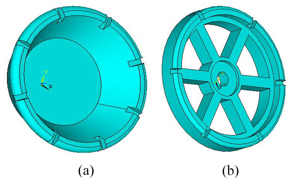
A complex disk tool: (a) solid complex disk and (b) hollow complex disk.
The analytical calculation of intrinsic frequencies for complex structures is often challenging and typically requires the utilization of simulation tools. In this study, the modal analysis of the tool shown in Figure 4 was performed using the finite element analysis software ANSYS. This analysis enabled the determination of the corresponding flexural vibration modes for the complex structure. The antinode was located at the disk’s center, and nodal circles were observed on the disk, as illustrated in Figure 5.

Modal simulation of a complex disk tool: (a) solid complex disk and (b) hollow complex disk.
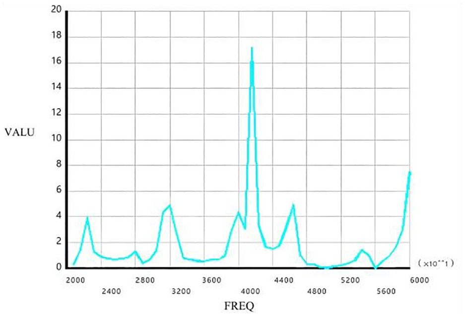
Taking the part shown in Figure 5(b) as an example, harmonic response analysis of the disk tool was conducted within the frequency range of 20–60 kHz using ANSYS software. The vibration displacement in the Z direction at a fixed point on the circumference of the tool was measured. The mode superposition was adopted by harmonic response analysis. A longitudinal load was applied to the center of the disc with an amplitude of 5 μm. The harmonic frequency range was set to 20 to 60 kHz with a number of subsets of 100. The loading method was stepped, and the curve varies with frequency was obtained by solving, as shown in Figure 6.

Harmonic response of a complex disk tool.
The extremum of longitudinal vibration displacement on the disk tool was observed at 24,066, 31,189, 40,200, 43,910, and 56,984 Hz, with the maximum displacement occurring at 40,200 Hz. The ultrasonic amplitude variation system was designed based on the complex flexural vibration characteristics of the disk. A longitudinal amplification horn, designed with a corresponding resonant frequency, was connected to the center of the disk tool at its small end using either a threaded or tapered connection method. This facilitated the conversion of the longitudinal excitation into flexural vibration of the disk. As a result, a circumferential vibration consistent with the direction of the longitudinal amplification horn was achieved. A longitudinal ultrasonic horn with a half wavelength at a frequency of 40,200 Hz was designed, and a uniform cross-section rod was used as a replacement for the calculation. The half wavelength of 45 # steel at this frequency is 64.3 mm. The longitudinal horn was combined with the disk tool shown in Figure 5(b), as illustrated in Figure 7, to form a compound ultrasonic vibration system.

Ultrasonic vibration system with a complex disk.
The compound vibration system was simulated and analyzed using ANSYS software. By performing a harmonic response analysis in the frequency range of 20–60 kHz, the Z-direction vibration displacement of a point on the circumference of the tool at different frequencies was obtained. Figure 8 shows several extreme displacement values observed at the measurement point on the circumference of the disk end face in the vibration system.
Harmonic response of the vibration system.
Frequencies corresponding to these extreme displacement values were 22,899.3, 31,954.4, 41,436.6, 46,653.7, 55,012.2 Hz, etc. The maximum longitudinal vibration amplitude occurred at a frequency of 41,501.6 Hz, which was close to the intrinsic frequency of 40,200 Hz at the maximum amplitude of the independent complex disk. Therefore, it can be inferred that the disk tool vibrated independently in a vibration system with a disk. In contrast, the connection between the disk tool and the horn functioned as a longitudinal vibration antinode.
Local resonance characteristics of the disk tool
The disk is connected to a longitudinal vibration system with the same intrinsic frequency. A uniform rod is initially employed to simplify the calculation and replace the longitudinal vibration system. An analysis of the modal properties of the complex disk is necessary to design a vibration system with a complex disk. ANSYS software obtained a resonant frequency of 24318 Hz for the complex disk at this frequency, as shown in Figure 9(a). The wavelength of the uniform rod was

Modal analysis of the ultrasonic vibration system: (a) Modal analysis at frequency of 24318 Hz, (b) Modal analysis of vibration system, and (c) displacement curve of vibration system.
The complete vibration system comprises a uniform rod with a diameter of 20 mm and a complex tool disk with a resonant frequency of 24577 Hz, exhibiting a discrepancy of 259 Hz from the theoretical value and an inaccuracy rate of 1.06%. Through testing (Figure 9(c)), the node is determined to be located at 52.4 mm, which is consistent with the theoretical design. When the longitudinal vibration system is combined with a disk tool of the same resonance frequency, the resonance frequency of the compound vibration system remains the same, and the system node remains unchanged. Designing a compound vibration system using this method can effectively mitigate the challenge of analytically calculating complex tools. In the above example, the simulated rod had a diameter of 20 mm. In comparison, the disk had a diameter of 80 mm, resulting in a diameter ratio of 1:4. It was observed that other parameters of the vibration system would not significantly affect the local resonance characteristics. In contrast, the diameter ratio was a constant. To further investigate this phenomenon, it is important to determine the range within which the dimensions of the disk and longitudinal vibrating rod can be altered while still maintaining this “local resonance” occurrence. Thus, one must clarify what conditions must be met by the diameter ratio of the horn and the disk to achieve the “local resonance” phenomenon.
A series of simulation experiments were conducted to address the above issues using the compound vibration system depicted in Figure 9. Both the uniform rod and disk were made of 45 steel, with material parameters listed in Table 3.
The disk size and structure remained unchanged, with an intrinsic frequency of 24,318 Hz. Based on this frequency, the length of the uniform rod was consistently set at 106.5 mm. Initially, the diameter was set to 48 mm, aiming for a resonance frequency of approximately 24,318 Hz for the compound vibration system.
The modal analysis revealed that the compound vibration system’s resonance frequency was 26,946 Hz, which was a deviation of 10.8% from the design frequency. As shown in Figure 10(a), the junction between the analog rod and the disk was not at the antinode of the disk, resulting in a significant offset from the antinode. The analog rod diameter was successively reduced by 4 mm in each iteration. The modal analysis results indicated that the resonance frequency of the compound vibration system gradually approached the theoretical value. Additionally, the junction of the analog rod and the disk progressively moved closer to the antinode of the disk, as shown in Figure 10(b) and (c).

Modal analysis of the compound vibration system with different analog rod diameters. (a) D = 48 mm. (b) D = 20 mm. (c) D = 12 mm.
Figure 11 demonstrates the trend of the resonant frequency of the compound vibration system as the diameter of the analog rod varies.

The resonant frequency transformation with the analog rod diameter.
Upon reducing the rod diameter to 16 mm, corresponding to the rod-to-disk diameter ratio of 1:5, the experimental resonance frequency of the compound system was 24,489 Hz, differing only by 0.74% from the theoretical value. Further reducing the diameter of the analog rod to 12 mm resulted in an even smaller error in resonant frequency, with a difference of only 0.37% compared to the theoretical value.
Based on the analysis, a smaller diameter ratio of the rod to the disk resulted in a closer proximity of the junction between the two components to the antinode. Consequently, the resonance frequency of the system was found to be closer to the theoretical value. This observation aligns with the principles of the local resonance theory applied to slender rods.
Design of a transducer for the compound vibration system
Design of a transducer for the compound vibration system with a disk tool
According to the modal analysis results in Figure 9, a sandwich piezoelectric transducer was devised utilizing a longitudinal frequency value of 24,577 Hz. The transducer comprises three segments: a reflector, a piezoelectric ceramic stack, and a transmitter. The front and rear terminals have a cylindrical shape with a diameter of 20 mm, while the right end of the PTZ stack serves as the nodal plane. The transducer is designed with a half wavelength, and each side of the nodal plane has a quarter wavelength, as shown in Figure 12.

Structure of a sandwich piezoelectric transducer.
For the reflective and transmitting ends, 45 steel was chosen, while PTZ8 was selected for the piezoelectric ceramic. The material parameters are detailed in Table 2. The frequency equation of a 1/4 wavelength transducer on the left side has the following form:

where Z1 and Z2 are the impedance values of the reflector and PZT, respectively, k1 and k2 correspond to the circular wavenumbers of 45 steel and PTZ-8 at 24,577 Hz, while L1 and L2 are the lengths of the two sections of the transducer.
The length L1 of the reflector in the transducer, which had an intrinsic frequency of 24577 Hz, was calculated as 15.6 mm. The PTZ stack had a length of L2 measuring 18 mm, while the transmitter had a length of 1/4 wavelength,
The transducer’s modal analysis results, displayed in Figure 13, were obtained using ANSYS software and indicated a resonant frequency of 24,724.4 Hz. The transducer was then assembled with the complex disk tool illustrated in Figure 9 to form a compound vibration system. Modal analysis was subsequently conducted on this new vibration system.

Modal analysis of the transducer.
Figure 14 shows that the intrinsic frequency of the compound system was measured at 24,669.3 Hz, which deviated from the theoretical value by 147.4 Hz, with an error of 0.599%. The axial displacement distribution curve of the compound system is shown in Figure 15, with a nodal position located at 33.25 mm. The simulation results exhibited a high degree of consistency with the theoretical design.
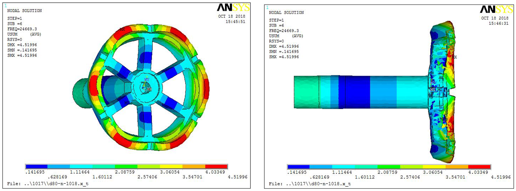
Modal analysis of the compound vibration system with a complex disk.

Axial displacement distribution curve of the compound vibration system with a complex disk
As shown in Figure 14, the intrinsic frequency of the compound system was 24,669.3 Hz, which differed from the theoretical value by 147.4 Hz, with an error of 0.599%. The axial displacement distribution curve of the compound system is shown in Figure 15, with a nodal position of 33.25 mm. The simulation results were consistent with the theoretical design.
Design of transducers for non-resonant compound vibration systems
Due to size constraints on the structure of ultrasonic vibration systems in certain machining scenarios, it is not feasible to design them according to the resonant frequency. The dimensions of the disk remained unaltered, and its longitudinal wave resonance frequency remained at 24318 Hz. To simplify the calculation process, a simulation rod with a diameter of 20 mm was initially employed to substitute the transducer for system assembly. The lengths of the simulation rod were subsequently reduced from 100.65 to 90 mm, 80, 70, 60 mm, and so on. These shortened rods were then connected to the disk for modal analysis. The simulation results are shown in Table 4.
Modal analysis results of non-resonant compound vibration system.

Figure 16 shows the modal simulation of the compound vibration system with a rod length of L = 70 mm. By summarizing and analyzing the above modal analysis results, it was observed that as the rod length decreased, the vibration frequency of the compound system gradually increased, indicating a more compact overall structure of the vibration system. Based on the examination of nodal positions in each system, it can be concluded that the nodal displacement of a non-resonant system was equal to 1/4 of the longitudinal wavelength at that particular frequency.

Modal analysis of non-resonant compound vibration system.
Based on the above analysis, the simulation rod has been redesigned as a half-wavelength sandwich piezoelectric transducer. This involves replacing the original uniform rods with a three-segment sandwich piezoelectric transducer on the left side of the nodal plane. On the right side of the nodal plane, a uniform rod with a length of H is maintained. The structural dimensions of these components are illustrated in Figure 17.

Design of non-resonant system transducers.
The frequency equation of a three-segment piezoelectric transducer with a 1/4 wavelength is as follows:

where k i is the circular wavenumber, Li corresponds to each section length, while Z1, Z2, and Z3 are the acoustic impedances of sections I, II, and III, which are derived as follows:

Taking the intrinsic frequency of the compound system, f = 32228 Hz, as a design example, the materials used for sections I, III, and IV are 45 steel, while the material for section II is PTZ8. Each section has a diameter of 20 mm, and k1 = k3 = 0.039. By substituting these parameters into equation (2), the dimensions of each part of the half-wavelength transducer were obtained as follows:

At this frequency, the transducer’s total length was 55.67 mm, and the theoretical nodal plane was located at
The compound vibration system was simulated using ANSYS software, and the modal analysis results are shown in Figure 18(a). The intrinsic frequency of the system’s longitudinal wave was 32,665 Hz, which differed from the theoretical value of 32,228 Hz by 437 Hz, resulting in an error of 1.36%.

Modal analysis of non-resonant systems (a) and displacement curve (b).
As shown in Figure 18(b), the transducer’s nodal plane was located at 25.78 mm, deviating from the theoretical value of 25.64 mm by 0.14 mm. The simulation results consisted of the theoretical design, indicating the accuracy and reliability of the design as mentioned above methods.
In situations involving complex disc tools, the local resonance characteristics can be harnessed to design a composite vibration system of any desired frequency. This approach facilitates meeting the working frequency requirements and structural dimensions necessary for the machining process.
Simulation and experimental verification of the compound vibration system
Based on the aforementioned theoretical analysis, the design method for a compound ultrasonic vibration system involving a complex disk involves the following steps:
(1) Establish a three-dimensional (3D) model of the complex disk according to the requirements and perform modal analysis on the model by ANSYS-soft to obtain the resonant frequency of the disk. As shown in Figure 19, according to the specified work requirements, a perforated disk with a diameter of 60 mm was designed, employing 7075 aluminum alloy as the material. The material parameters, including density and acoustic velocity, are presented in Table 2. Through modal analysis, the disk’s resonant frequency of 36,111 Hz was determined.
(2) Based on the simulation results of the complex disk, design an ultrasonic transducer with the same frequency as the disk.

ANSYS simulation of a complex disk.
A sandwich transducer was designed with a frequency of 36,111 Hz. The transmitter and reflector were made of 45 steel, while the two-piece ceramic stack comprised axially polarized PTZ8. The dimensions of each component of the transducer were calculated and are illustrated in Figure 20. The theoretical node plane was positioned at 26.2 mm, with a rear end of 15.7 mm, a front end of 39.5 mm, an 8 mm ceramic plate, and a total length of 63.5 mm, excluding the bolt length. The transducer has been simulated, and its modal analysis structure is shown in Figure 21. The resonant frequency was 35,857 Hz, which closely approximated the theoretical value.
(3) Assembling the transducer with the complex disk, followed by modal and transient dynamic analyses on the compound vibration system.

Design of transducers with 36,111 Hz.

Modal analysis of transducers.
The compound vibration system was created by assembling the complex disk, depicted in Figure 19, with the transducer shown in Figure 21. Simulation analysis was performed using ANSYS-soft, and the modal analysis results are shown in Figure 22. The analysis indicated that the resonant frequency of the ultrasonic system was 36,566 Hz. There was no significant shift in the node position. The transient dynamic analysis results, shown in Figure 23, revealed the response of the compound vibration system under a periodic displacement function.

Modal analysis of compound vibration system.

Transient dynamics analysis.
A longitudinal excitation signal was applied to the rear end of the vibration system, with a wave form of function s = 5 × 10⁻⁶sin(2π × 36566 × t). Fixed points were taken at the rear end, node, and disk of the system to observe the transient displacement. The blue curve in Figure 23 represented the displacement response of the fixed point at the rear end of the system, while the red and purple curves were the displacement response at the disk and nodes of the system respectively. It was seen that the displacement at the rear end of the system was a sine wave, which was consistent with the applied signal. The displacement at the disk of the system also varies periodically, with a maximum amplitude not lower than that at the end. Some displacement were observed at the nodal plane of system, but the amplitude was relatively small. The analysis results indicated that the vibration system was consistent with the theoretical design.
(4) Based on the 3D model’s dimensions and materials, various components were manufactured and assembled to obtain a compound vibration system incorporating a complex disk. Based on the parameters of the three-dimensional model mentioned earlier, a perforated disk and different components of the transducer were machined and assembled to create a compound vibration system with a complex disk. The characteristics of the system, including the natural frequency, dynamic resistance, quality factor, and other parameters were measured using a PV70A Impedance analyzer, as shown in Figure 24. The obtained values were a resonant frequency of f = 34039 Hz, a dynamic resistance R1 = 88.6 ohm, and a quality factor Qm = 786.

Impedance test of compound vibration system.
Applying longitudinal excitation to the compound vibration system, longitudinal vibrations were generated on the transmitter and subsequently transmitted to the disk. The longitudinal vibration amplitudes at the end of the system, the edge of the disk, and the flange of the system were measured by a Kearns LK-G10 laser displacement sensor, as shown in Figure 25(a). It was presented in Figure 25(b–d) the longitudinal amplitude at the flange was measured as 0.3 μm, an average amplitude of 2.5 μm was recorded at the edge of the disk, with a maximum of 3.2 μm, and the longitudinal amplitude at the rear plate reached an average of 3.0 μm, respectively.

Amplitude testing of compound vibration system: (a) ultrasonic amplitude measurements of compound vibration system, (b) longitudinal amplitude of flange, (c) longitudinal amplitude of disk, and (d) longitudinal amplitude of rear end.
The theoretical value of the resonant frequency of the system was 36,566 Hz, while the experimental results show that the resonant frequency of the system was 34,039 Hz, with the error value of 6.9%.From the perspective of vibration displacement response, the theoretical and experimental results were basically consistent.
Conclusions
In this study, the vibration characteristics of an ultrasonic system with a thin disk were studied, and a universal design method for the ultrasonic vibration system was obtained. The analysis results showed that the thin disk has local resonance characteristics of slender rods in the vibration system. Furthermore, the non-resonant system design method of the vibration system was discussed, and the integrated design theory of the transducer and horn was obtained, providing theoretical guidance for determining the nodal position of the system.
(1) Flexural vibrations of thin disk generally occur with the disk center serving as the vibration antinode. Connecting a longitudinal vibration amplification rod to the antinode of the disk and applying longitudinal ultrasonic excitation to this antinode, a flexural vibration disk with the same intrinsic frequency as the longitudinal vibration rod can be obtained. Longitudinal vibration consistent with the end of the longitudinal horn is generated at the disk’s center. Simultaneously, longitudinal vibration in the same direction also occurs on the circumference of the disk. If there were cutting edges on the entire circumference, a disk with cutting edges, which is equidistant from the center and vibrates longitudinally with equal amplitude, can be achieved. The vibration system for cutting discs such as grinding wheels can be designed using this theory.
(2) A design method for a ultrasonic vibration system with disc was proposed in this study. A compound vibration system can be formed by combining a vibration system with a disk with the same resonance frequency. In this system, the disk can vibrate independently while the resonance frequency of the compound system is close to the original system. This approach provides a solution for analyzing and calculating complex disks that are challenging to handle through traditional methods. The results indicated that: when the diameter ratio of the horn to the disk is smaller, the junction between the two components is closer to the vibration antinode. Consequently, the resonance frequency of the compound system aligns more closely with the theoretical value. This finding is consistent with the local resonance theory of slender rods.
(3) The design method of non-resonant ultrasonic vibration system with disc was studied. In case of size limitations on the structure of the ultrasonic vibration system, non-resonant frequency ultrasonic system design can be carried out. The sandwich transducer should be designed based on the resonant frequency of the disk. Depending on the specific work requirements, the rod length can be shortened, resulting in a corresponding increase in the resonant frequency of the compound vibration system. The theoretical node of the non-resonant compound vibration system is positioned at 1/4 wavelength of its resonant frequency. Based on this approach, any desired non-resonant compound vibration system with a disk can be designed.
(4) The performed numerical simulations and their experimental verification proved that the developed compound vibration system exhibited slight resonance frequency deviations from the theoretical predictions, which can be attributed to processing, installation, and testing errors. However, a good agreement of experimental and simulation results proved that this study established a robust design method for compound vibration systems with a complex disk.
Footnotes
Acknowledgements
The authors would like to acknowledge the Key R&D and Promotion Program (Science and Technology) in Henan Province, China, the Key Research Project for Higher Education Institutions in Henan Province, the China Postdoctoral Science Foundation, the Postdoctoral funding project of Henan Province, the Young Backbone Teacher Training Program in Henan Province, and the Doctoral Research Fund Project of Henan University of Animal Husbandry and Economy.
Handling Editor: Sharmili Pandian
Declaration of conflicting interests
The author(s) declared no potential conflicts of interest with respect to the research, authorship, and/or publication of this article.
Funding
The author(s) disclosed receipt of the following financial support for the research, authorship, and/or publication of this article: This research was financially supported by the Key R&D and Promotion Program (Science and Technology) in Henan Province (232103810044, 222102310546), the Key Research Project for Higher Education Institutions in Henan Province (22B460011), the China Postdoctoral Science Foundation (No. 2023M730984), the Postdoctoral funding project of Henan Province (No. HN2022163), the Young Backbone Teacher Training Program in Henan Province, China (2023GGJS149), and the Doctoral Research Fund Project of Henan University of Animal Husbandry and Economy (2020HNUAHEDF005, 2022HNUAHEDF016).