
Abstract
The development of a versatile and reliable robotic arm for agricultural picking is essential for modern farming. This study presents the design of a picking robotic arm inspired by bionics principles. The end-effector features a parallel gripper structure to efficiently pick crops of various shapes and sizes, with finite element simulations confirming its structural rationality. The gripping force is measured by an LDTI-028K PVDF piezoelectric thin-film sensor, adjustable within a crop-safe range to prevent damage. Additionally, a new signal conditioning circuit is proposed to improve the signal-to-noise ratio by amplifying the sensor’s output signal and minimizing noise, addressing the relatively low surface charge produced by the PVDF film under external pressure. Adams simulation analyses show that the end-effector is highly adaptable. Furthermore, picking experiments demonstrate that the robotic arm can reduce costs and lower the attrition rate by approximately 23.2 ± 5% compared to manual picking, while also exhibiting high reliability and stability.
Introduction
Agriculture is essential to national economies, and modernization of agriculture is a global trend. China’s fruit and vegetable cultivation comprises about 20.39% of global agricultural land. 1 However, the aging population and expanding urban areas have led to a severe shortage of agricultural labor. Currently, human labor constitutes 50%–70% of fruit and vegetable picking costs, 2 which itself accounts for 50%–60% of total production expenses. 3 The inefficiencies of manual picking methods underscore the need for autonomous picking solutions. The manual picking method has proven inadequate in meeting the demands of modern times. The picking mechanical arm is a mechanical apparatus capable of emulating the actions of the human hand, thereby achieving autonomous picking capabilities. 4 This technology can enhance work efficiency and alleviate labor intensity.
Similarly, Japan is facing a severe labor shortage in agriculture, Panasonic developed a tomato-picking robot that uses a high-precision camera to locate and pick the fruit. 5 Zheng et al. designed a robot that integrates tree climbing and coconut picking functions, capable of climbing coconut trees up to 13.42 meters with good climbing and picking efficiency. 6 The Netherlands Agricultural Engineering Research Institute developed a multifunctional modular cucumber picking robot, which has a steady state accuracy of ±0.2 mm and a picking success rate of 80%. 7 Bao et al. designed a dual-robot cooperative citrus picking system based on a global scanning picking scheme and genetic algorithm for trajectory planning, which was able to improve the picking success rate to 82%. 8 Zhou et al. proposed an apple picking robot control method based on 3D point cloud data, which was able to improve the success and reliability of picking in unstructured environments, with a picking success rate of 82% and a picking cycle time of 11.1 seconds. 9 Scholars at the National Research Institute of Japan studied a five-degree-of-freedom aubergine picking robot with an end-effector consisting of a finger, an inducer rod and pneumatic shears. 10 Spain developed a tractor-driven citrus-picking robot with a sensing system that determines the ripeness of citrus grades them by color, and operates at a speed of 1 s/pc, six times faster than manual picking. 11 Kyungpook National University in South Korea developed a degree-of-freedom apple-picking robot, which determines ripeness through CCD vision sensors and photoelectric sensors, with a recognition success rate of 85% and a picking speed of 5 s/pc. 12 A machinery company in California, USA researched a fully automatic tomato picking robot arm, the machine is 12.5 m long and 4.3 m wide, with an operating efficiency of 70 t/h. 13 China Agricultural University designed a cucumber picker robot, which has a picking success rate of about 85%, a picking speed of about 8 s/root, a maximum error of −7 mm in the positioning of its vision system, and a fruit recognition rate of about 95%. 14 Meanwhile, scholars from this university also studied the ripe tomato localization technique, with recognition errors between 3% and 4% when the distance between the vision system and the target tomato was between 300 and 400 mm. 15 China Agricultural University studied the recognition and localization technology of apple stalks under natural light conditions, with a recognition success rate of 80%. 16 The Jilin University of Technology researched a mushroom-picking robot based on a vision system with a picking speed of 70–80 pcs/min. 17 Northeast Forestry University developed a five-degree-of-freedom forest ball fruit-picking robot with an operating efficiency of 500 kg/day, which increased the efficiency of picking by 30–50 times than manual picking and minimized the damage to trees. 18 The Institute of Automation of the Chinese Academy of Sciences and China Agricultural University jointly designed a strawberry damage-free automatic picking actuator with an average picking speed of 73.6 pcs/h and a picking success rate of 90%.19,20 The researchers proposed an efficient, stable, and non-destructive automated fruit and vegetable picking system using a global-local vision servo, an improved GMOPSO algorithm, and a virtual spring-based configuration planning method, with experiments showing superior performance in accuracy, time, energy, and stability.21–23 In addition, Guo et al. designed an automated straddle harvester tailored to pineapple planting patterns and growth characteristics, with virtual modeling and simulation showing that the harvester’s efficiency reaches 1,636 plants per hour, twice the rate of manual picking. 24
Although progress has been made in development, functionality remains limited due to the specific design of the actuator. For example, the automatic strawberry-picking actuator developed by the Institute of Automation at the Chinese Academy of Sciences, as previously mentioned, can swiftly and gently pick strawberries but is unable to handle other types of produce with varying shapes and sizes, such as aubergines or tomatoes. Additionally, selecting lychees that closely resemble strawberries introduces unpredictability to the picking success rate and increases the risk of financial loss, highlighting the low reliability of this picking method.
Therefore, this paper presents the design of a robot arm equipped with a parallel gripper structure, enabling efficient picking of crops of various shapes and sizes. The proposed design offers high versatility and cost-effectiveness. The robotic arm uses a tandem rod structure driven by a motor, which powers the gearbox to move both the large and small arms. The small arm, in turn, drives the end-effector, delivering high efficiency and sensitivity.
Overall structural design of picking robot arm
The pickup process involves an electric system in which a motor on the chassis drives the entire robotic arm to rotate close to the crop that needs to be picked up, and once accurately positioned, the dual motors on the large arm drive the gears in the gearbox to rotate and drive the robotic arm in motion, which subsequently activates the dual motors on the end-effector to ensure accurate pickup, as shown in Figure 1.

Workflow diagram of the picking robot arm.
End-effector structure design
This article applies the concept of biomimicry to develop an end-effector with a parallel gripper claw structure, specifically designed for efficient picking of crops in various shapes and sizes. The handle of the claw is made of cast aluminum (ADC12), known for its excellent strength and corrosion resistance. For the claw itself, silicone rubber (LSR) is preferred to minimize potential damage to crops during picking, as shown in Figure 2.

End-effector structure.
The robotic arm’s capacity to precisely grasp things is directly linked to the clamping inaccuracy of the end-effector. The design requirements mandate that the gripping error of the hand claw must not exceed 6 mm. Figure 3 depicts the gyratory hand claw successfully holding a crop.

Rotary manipulator claw.
Where LAB is the length of the hand claw, the distance between the two pivot points from point
Figure 4 displays the structural line diagram of the rotating hand claw. The distance between point

Line drawing of the structure of the transformation hand claw.
This is known from the geometric relationship:
To wit:

Change the equation to

Or it could be changed to a hyperbolic equation:


Clamping error refers to the amount of change in the radius of the clamped object from the minimum to the maximum value, the change in S-value, denoted by
When

When

In designing the end-effector,
After completing the structural design of the end-effector, the clamping error needs to be calibrated. If the diameter of the clamped object is in the range of 50–80 mm, a is taken as 35 mm, the rounding angle


From there, it counts:

From this comparison

Therefore, the clamping error of this end-effector meets the design requirements.
Other structural design
The mechanical arm uses a tandem rod configuration consisting of two side connecting plates and pins linked by pinholes, with a central pin also connected by pinholes. This design significantly reduces the arm’s weight while enabling a broad range of motion control for the end-effector. The arm comprises a large arm and a smaller arm: the lower section of the large arm connects to the gearbox on both sides, with one end attached to the small arm and the other end to the end-effector. Made from cast aluminum (ADC12), the arm is lightweight yet provides structural stability, enhanced rigidity, and strength.
The arm’s joints possess a rotating joint structure, enabling the arm to execute circular movements horizontally. The joints are made of aluminum alloy (6160-T6), which possesses adequate strength and stiffness.
The base employs a spacious chassis with a structure that maintains a low center of gravity, hence enhancing the stability of the robot arm. The rotary chassis and rotating disc are constructed using cast aluminum (ADC12) due to its exceptional strength, stiffness, and ability to endure the weight of the robot arm and vibrations during operation.
The robotic arm’s rotary structure includes rolling bearings made of carbon structural steel (Q275), chosen for its high load-bearing capacity and durability. This material ensures excellent flexibility and motion accuracy in the arm’s operation. Table 1 summarizes the primary characteristics of these materials.
Main parameters of materials.
Power part design
The drive motor for the picking robotic arm should be selected based on the specific functional needs and requirements of different parts. The motor position is indicated in Figure 5.
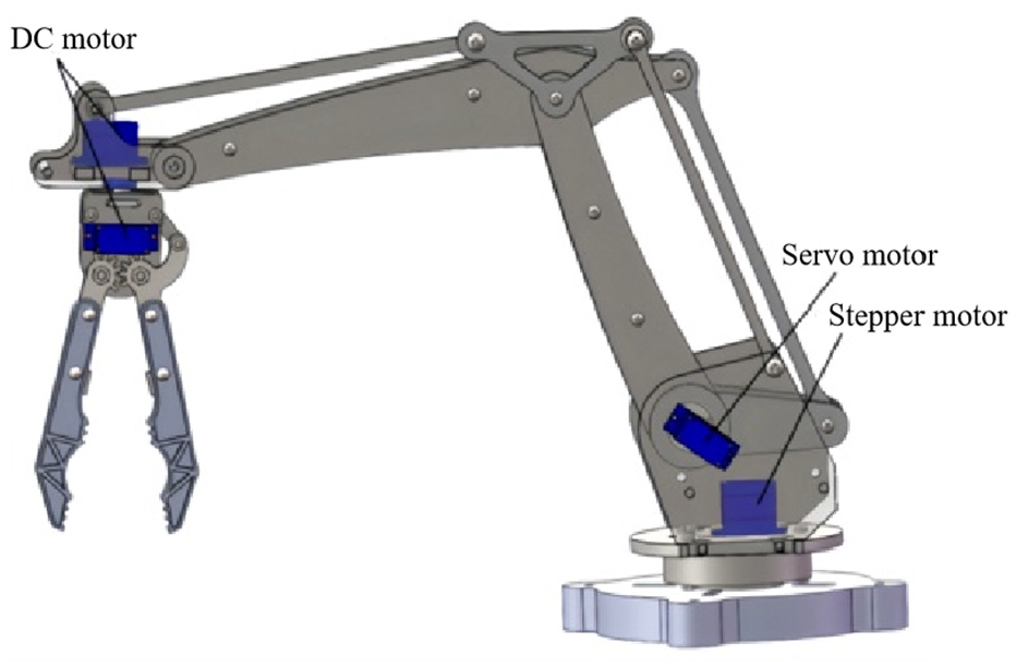
Selected motor position of the picking robot arm.
The end-effector part can choose a DC motor or brushless motor. Considering the cost, the DC motor is chosen in this paper. For the joint parts, servo motors or stepper motors are usually chosen. As the joints of the picking robot arm need precise control and high power output, the servo motor is chosen after comparison.
Due to the sufficient rotational force and speed control of the base, the motors usually selected are DC motors or stepper motors. Through analysis, this paper selects a stepper motor. The main parameters of the above motors, as shown in Table 2.
Main motor parameters.

Finite element analysis of mechanical jaws
In order verify the rationality of the structure, this research use the simulation module within the SolidWorks 2023 software to conduct finite element analysis of the manipulator claw. This research specifically examines the static stress analysis of the mechanical hand claw, which is the primary component that comes into contact with the crop during the picking process. Prior to conducting the simulation, this study opted for cast aluminum (ADC12) as the material for the handle of the hand claw, and silicone rubber (LSR) as the material for the hand claw.
Additionally, two cylindrical apertures at the tip of the robotic hand claw serve as fasteners to secure the hinge. To simulate the pressure encountered by the manipulator during actual picking, an external load of 4 N is applied. The stress cloud force diagram in Figure 6(a) reveals a maximum stress value of only 5.856 MPa well below the silicone rubber’s yield strength of 7 MPa. This suggests that the robotic gripper will remain intact and undamaged during operation, without any risk of plastic deformation. As shown in Figure 6(b), the red area at the gripper tip displays the highest displacement, measuring precisely 0.183 mm. This level of displacement satisfies the overall positioning accuracy requirements, indicating that the gripper can maintain sufficient precision for effective picking.

Analyzed results: (a) stress cloud diagram and (b) displacement cloud diagram.
In summary, based on the analysis conducted, it can be inferred that the mechanical gripper withstands an external force of 4 N without exceeding acceptable stress and displacement levels. This confirms that the gripper meets the required parameters for picking tasks. Thus, the finite element analysis validates the robotic gripper’s dependable and consistent performance.
Flexible PVDF piezoelectric film sensor
PVDF thin-film sensors utilize the piezoelectric effect, offering advantages such as a high piezoelectric constant, excellent flexibility, and enhanced sensitivity. Additionally, PVDF sensors are flexible polymer film devices that can be easily attached to curved surfaces. With low impedance, they can deform even under minimal force. In this study, the LDTI-028K PVDF piezoelectric thin-film sensor was used to measure clamping force. Specific performance parameters are provided in Table 3.
Performance parameters of PVDF.

This sensor utilizes a piezoelectric film that is 28 μm thick. The film is positioned on a polyester substrate that is 0.125 mm thick. It is then connected to two crimp terminals to direct the electrodes. When exposed to vibration, the PVDF piezoelectric film experiences a flexing action, resulting in the stretching and contracting of the film. Figure 7(a) and (b) displays the film structure and notch structure of the PVDF.
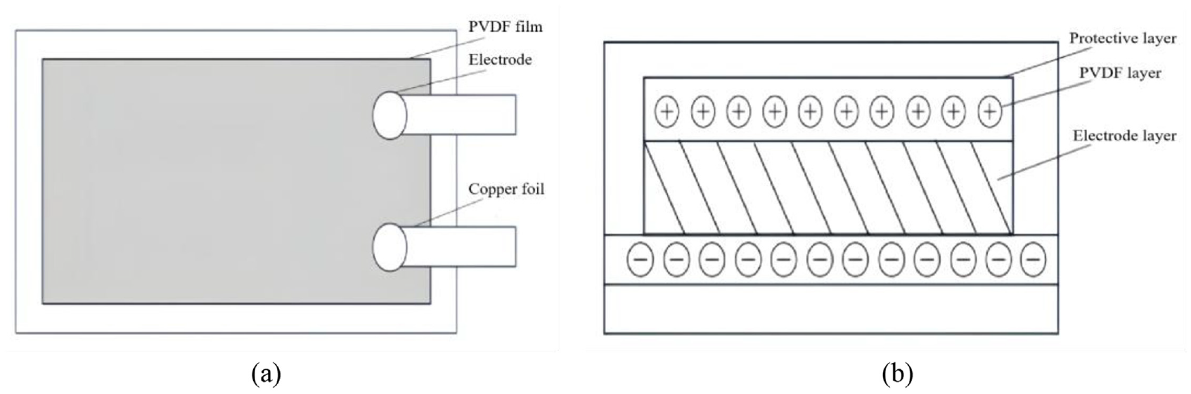
PVDF structure: (a) structure of PDVF film and (b) PDVF cutting structure.
This study proposes a new signal conditioning circuit to address the issue of the comparatively low surface charge produced by PVDF piezoelectric films when exposed to external pressures. By enhancing the amplitude of the sensor output signal and minimizing the noise level, the signal-to-noise ratio is improved. The conditioning circuit comprises a preamplifier module and a low-pass filter module, aimed at amplifying and conditioning the charge signal produced by the sensor. In this study, a functionally integrated chip design is employed to tackle the stability and noise problems commonly found in traditional operational amplifiers that utilize resistors and capacitors. Figure 8 illustrates the incorporation of components such as VK10x and UAF42 in the design. This paper effectively enhances the system’s performance and improves its suitability for intricate operating environments.

Hardware circuit structure.
The preamplifier module in this setup utilizes the VK10x design for the charge amplifier. Its primary purpose is to convert the high-impedance charge signal produced by the PVDF piezoelectric film into a low-impedance voltage signal, thereby enhancing the amplification of the sensor’s output signal. To mitigate the impact of high-frequency noise on system performance, this study employs a UAF42 active filter module to effectively filter the signal, with the filter frequency specifically set at 50 Hz. The chosen processing module is the STM32F103RCT6 microcontroller, which is equipped with a high-speed A/D converter capable of swiftly converting analog voltage signals into digital signals. Furthermore, the processing module includes a serial communication module, an SWD download port, and a crystal oscillator module to facilitate data and program transfer, ensuring the proper functioning of the microcontroller, as depicted in Figure 9.
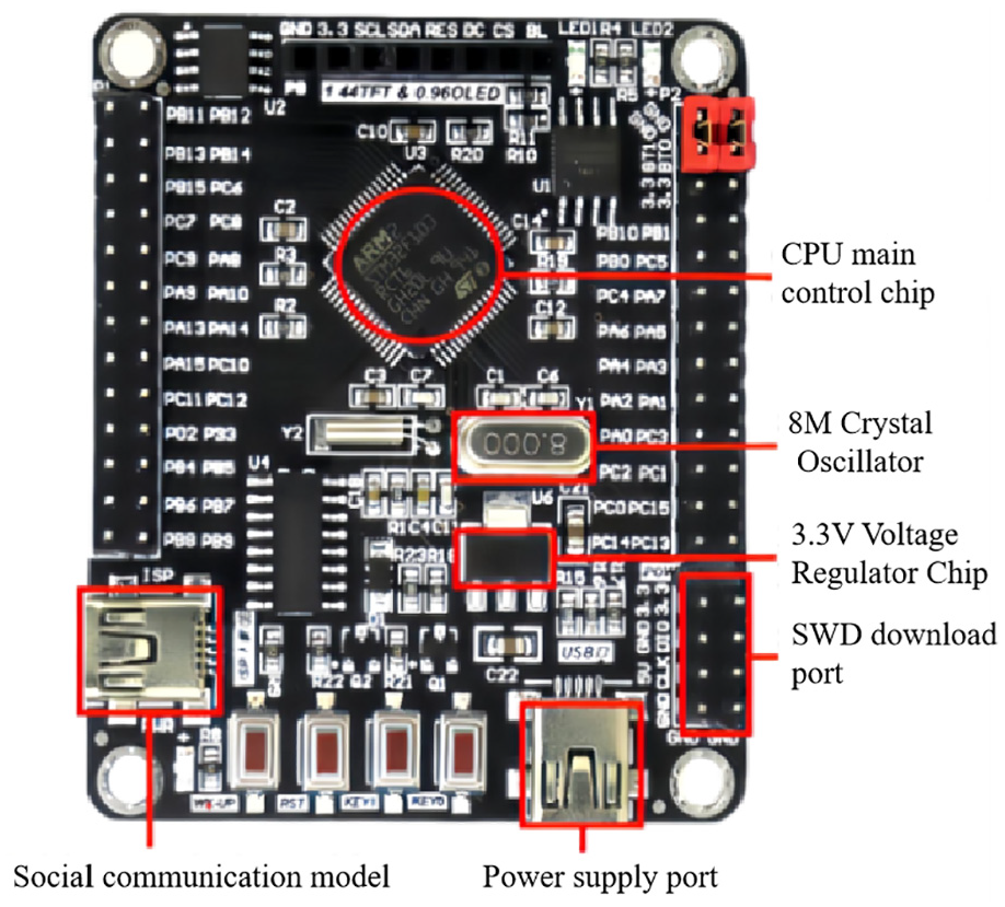
STM32F103RCT6 microcontroller.
Dynamic simulation and analysis
Interactive simulation method
This study utilizes an interactive simulation approach to conduct simulation modeling and analysis using Adams. The simulation findings are then transferred to the main system, which retrieves the simulation outcomes and communicates them back to the Adams model. Furthermore, the primary system continues to transmit the simulation signals to the Adams model. Once this stage of simulation is completed, the next stage is executed consecutively. The robot arm’s applicability during the working process is ensured by selecting various objects with different shapes as targets to compare the data differences when clamping them. Figure 10 displays the workflow.

Interactive simulation process.
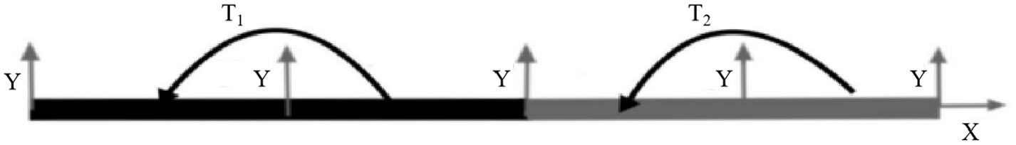
The proportional differential control approach is employed to regulate the location of the picking robotic arm. The schematic representation of the shortened model of the picking robotic arm 23 is depicted in Figure 11.
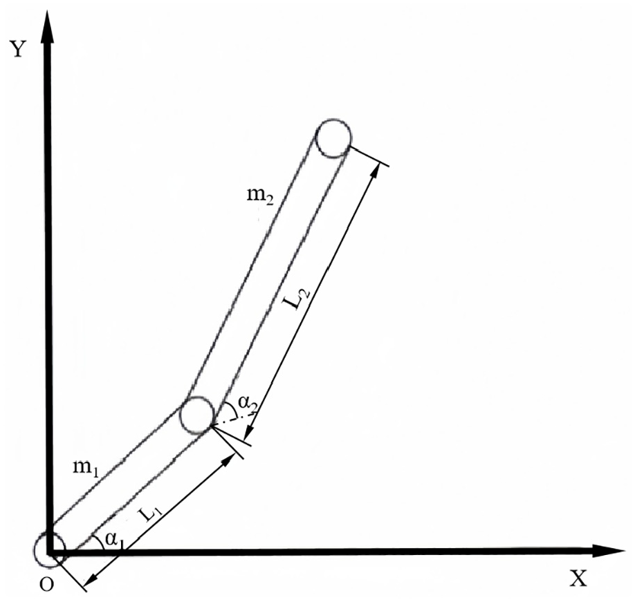
Sketch of the picking robot arm model.
From Figure 11, it can be seen that the robot arm 1 is attached to the ground, and there is a connection between robot arm 1 and robot arm 2. The angle vector of the robot arm is
Without considering other factors, the equations of the system are:
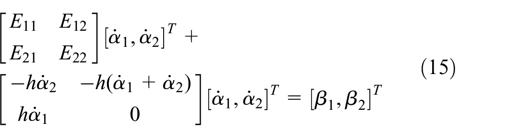
Format:

The main parameters of the two robotic arms as well as the angles are shown in Table 4. The robotic arm is simulated using Adams software. Two moments,
Main parameters of the robotic arm.

Sketch of the robotic arm model.
Because the Controls core module in Adams relies on state variable values, the established output and input variable values are related to their state variable values. In order to achieve controllability of the model in Figure 7, control output input variable values have to be established. In order to comply with the requirements of the proportional differential control method, four state variable values need to be set up, which are, in order, torque
Establish a control law:

Where:
Always for:

The total energy

The system’s stability is determined by applying Lyapunov’s stability theorem. The implementation of the calibrated control law enables the development of a distinct control module, as depicted in Figure 13(a).

(a) Control module, (b) experimental results, (c) material properties of the model, and (d) simulation settings.
By configuring the working period of the system module to 1 s, we obtain the results of the discrepancy between displacement 1 and the target value, and the discrepancies between displacement 2 and the target value, as depicted in Figure 13(b).
It is evident that both robotic arm 1 and robotic arm 2 can rapidly achieve the desired angles, indicating that Adams’ interactive simulation method is capable of handling various intricate system controls and can be utilized for simulating and analyzing the picking robotic arm designed in this study.
Dynamic simulation
To analyze the model using Adams software, it is necessary to convert the model created in SolidWorks into a format compatible with Adams and then import it into the Adams program. The simulation study considers the working environment to be in the MMKS unit system and accounts for the influence of gravitational acceleration (g = 9.80665 N/kg) in the vertical direction. Before studying the dynamics of the robotic arm, it is imperative to use the program to specify the density of the model material as a mass-to-volume ratio and to establish the relevant material attributes. Figure 13(c) and (d) indicate that the simulation time is set to 8 s, the step size is set to 500, and the simulation method is chosen as interactive.
Adams is used to conduct a dynamic simulation analysis of the robotic arm in order to confirm its ability to pick crops of various shapes and sizes. Three simulation models, namely model A, model B, and model C, are created for this purpose. The robotic arms in all three models are identical, with the only difference being the shapes and weights of the objects they pick.
The specific parameters for each model are provided in Table 5, while simulation model A and simulation model B are shown in Figure 14.
Main parameters of the model.


Simulation models: (a) model A and (b) model B.
By conducting a dynamics simulation and analyzing the curve diagrams of each joint and part, the disparity becomes more apparent when examining the angular displacement and angular velocity curve diagram of the contact force exerted on the moveable jaw, as depicted in Figure 15(a). The driving torque graphs for the motor in the motor box of the large arm and the motor of the slewing base are shown in Figure 15(b) and (c).

Simulation data: (a) contact force of the slave jaws gripping the object, (b) motor drive torque in a large arm motor case, and (c) motor drive torque for base rotation.
Based on Figure 15(a), it is evident that among the three models, Model B exhibits the highest contact force at 6.4 s. Model A demonstrates the most consistent performance in terms of the contact force variation curve, when compared to the other two models.
Upon examination of Figure 15(b) and (c), it is evident that the motor driving torque curves of Model A on the motor box of the large arm and the slewing base exhibit more stability in comparison to those of Model B and Model C. The torque curves of Model A exhibit greater stability in comparison to those of Model B and Model C. At a particular instant, the contact force and driving moment for model B experience a sudden and maximal increase. Table 6 displays the precise values for the three models, derived from the computation of contact forces and driving moments depicted in Figure 15(a) to (c).
Calculation results.
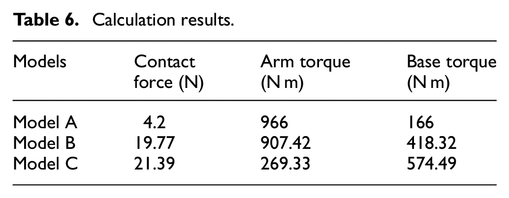
According to the statistics in the table above, it is evident that both Model B and Model C surpass Model A significantly in terms of contact force and base moment. Specifically, Model B exceeds Model A by a factor of 4.7 in contact force and 2.52 in base moment, while Model C exceeds Model A by a factor of 5.1 in contact force and 3.5 in base moment. Furthermore, as the weight of the grabbed object becomes greater, both the contact force and the base slewing moment of the action jaws also rise. Model A significantly outperforms the other two models in terms of large arm moment, with values that are 1.1 and 3.59 times greater than them, respectively.
Through the comparison and analysis of the passive clamp contact force curves of the three models, we can determine the closure force index of the end effector. By analyzing the data provided in the charts regarding the motor-driven torque and engine-driven base slewing torque, we can make informed assessments about the load capacity and flexibility performance of the robotic arm. For detailed details, please consult Table 7.
Performance comparison of the three models.

Based on the data provided in the table, it can be deduced that Model C exhibits the highest closing force among the three models, indicating superior gripping ability of the end-effector. Models A and B demonstrate better weight-carrying capability and flexibility, while Model C performs poorly in these areas. Model A is deemed the optimal choice. Furthermore, regardless of the model, the operational procedure consistently requires 8 s, ensuring uniform efficiency. In summary, the robotic arm demonstrated its capacity to securely hold objects of both cylindrical and rectangular shapes, confirming its suitability for picking crops of various sizes and forms.
Grabbing experiment
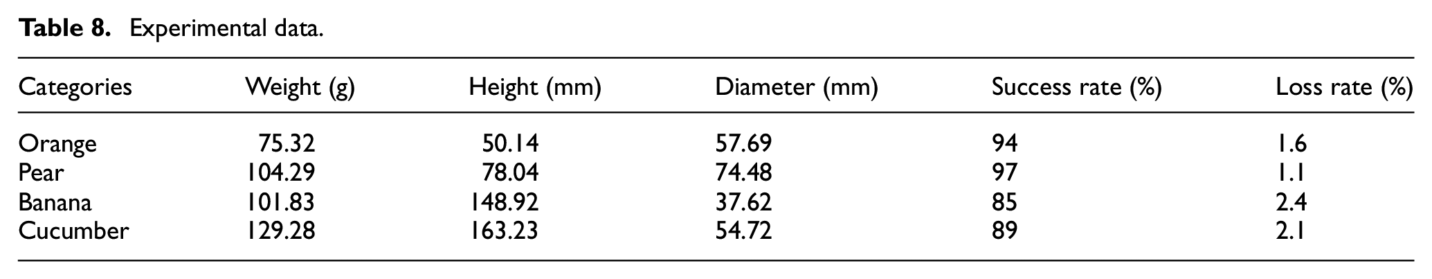
To further demonstrate the feasibility of the robot arm grasping crops of different shapes and sizes, four fruits and vegetables of different sizes and weights (oranges, pears, bananas, and cucumbers) were selected for the grasping experiments in this paper, as shown in Figure 16. The weights, average diameters, heights, and success rates of the grasping targets are shown in Table 8. From the data in Table 8, it can be seen that the grasping success rates of bananas and cucumbers are lower than those of oranges and pears, which are 85% and 89%, respectively. This is because the diameter of banana and cucumber is relatively small and the weight is still relatively large, the clamping range of the two end effectors is insufficient, which can not adapt to the long surface of the fruits and vegetables, so the pressure required for gripping banana and cucumber is larger, which causes a certain loss rate. Oranges and pears had smaller loss rates of 1.6% and 1.1% respectively. For reference, 25 the general wastage rate of manual picking is 25±5%, while the robotic arm designed in this study has an average wastage rate of 1.8%, which is 23.2±5% lower compared to the wastage rate of manual picking.
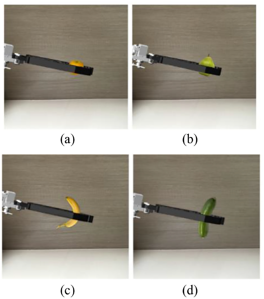
Grabbing of four crops: (a) robotic arm gripping an orange, (b) robotic arm gripping a pear, (c) robotic arm gripping a banana, and (d) robotic arm gripping a cucumber.
Experimental data.
In addition, the grasping time for each fruit and vegetable was recorded in this paper. Depending on the grasping phase, the completion time was divided into three stages: In the first stage, the hand claw opens, and the manipulator arm moves, which takes about 2.72 s on average. In the second stage, the hand claw closes, and the manipulator arm raises. For a spherical crop, this stage takes about 2.95 s, while for elongated crops, where the manipulator must be rotated to the appropriate angle, it takes about 5.26 s. In the third phase, the manipulator arm moves, and the claws open to enter the target area, which takes about 3.50 s on average. Therefore, the total gripping completion time is approximately 8.71 s for both spherical and elongated crops.
According to the literature, 26 robotic arms have been shown to enhance picking efficiency and reduce labor costs and time compared to manual labor. Consequently, a greater amount of picking can be accomplished within a reduced timeframe, leading to increased productivity and effectiveness. Nevertheless, it is important to consider the expenses associated with maintaining robotic arms and the potential of operational interruptions. Maintenance costs include routine servicing of the robotic arm, procurement of replacement parts, and remuneration for maintenance personnel. Excessive maintenance costs can adversely affect the economic viability of the robotic arm. Furthermore, system unavailability is a significant concern, as downtime resulting from failures of the robotic arm or other factors may impact the continuity of picking operations and productivity. However, by implementing effective maintenance strategies, it is possible to significantly decrease failure rates, leading to reduced downtime and lower maintenance expenses. As depicted in Figure 17, the cost of the robotic arm decreases steadily over time, eventually stabilizing, while labor costs grow gradually. This trend highlights the benefits of utilizing the robotic arm.

Human-machine cost comparison.
The experimental findings demonstrate that the robotic arm, equipped with a parallel gripper structure, is capable of efficiently and reliably grasping fruits and vegetables of various shapes and sizes while maintaining stability and good performance. Compared to manual labor, the robotic arm achieves significant cost savings and reduces the loss rate by approximately 23.2 ± 5%.
Conclusion
To enhance the usability of the pick-up robotic arm and minimize attrition and expense, this study designed a pick-up robotic arm and conducted simulation analyses and experiments. The primary findings can be summarized as follows:
(1) The end effector adopts a parallel structure, which effectively reduces the clamping errors. This design provides a better fit for picking actions.
(2) Through interactive simulation experiments showed both robotic arm 1 and robotic arm 2 can achieve the ideal angle in a short time. This demonstrates that Adams’ interactive simulation method can handle a variety of complex system controls.
(3) The picking experiment confirm that the robotic arm developed in this study is capable of efficiently and consistently picking crops of various shapes and sizes. Furthermore, compared to manual picking, the use of the robotic arm results in cost savings and a reduction in the wastage rate by 23.2 ± 5%.
Additionally, the four corners of the base of the robotic arm designed in this study are fixed to the agricultural vehicle. This setup improves its picking flexibility and addresses the structural stability problem. The main material of the mechanical arm is cast aluminum, while the end effector is made of aluminum alloy and silicone rubber. This combination prevents rust and corrosion, allowing it to be used for picking in various weather conditions. However, there are still some defects, such as the agricultural vehicle being unsuitable for driving on challenging terrains like large slopes and inclined ground. The above shortcomings will be addressed in future research.
Footnotes
Acknowledgements
We are grateful to the reviewers and editors for their valuable comments and suggestions.
Handling Editor: Chenhui Liang
Declaration of conflicting interests
The author(s) declared no potential conflicts of interest with respect to the research, authorship, and/or publication of this article.
Funding
The author(s) disclosed receipt of the following financial support for the research, authorship, and/or publication of this article: This work was supported by High Level Talent Research Foundation of Jinling Institute of Technology (Grant number jit-b-202227).