
Abstract
As a novel robot which mainly engages in the demolition and transformation of various concrete buildings, the demolition robot has developed rapidly in recent years. The impact force is mainly produced by the breaking hammer installed in the front end of the arm. As the most important part of a demolition robot, the boom arm is mainly composed of four parts including a supporting arm, a main arm, a fore arm, and a breaking hammer system. In this article, a mechanical model of the boom arm is established, and the finite element analysis obtaining the first four-order natural frequencies and modes is carried out in ANSYS Workbench. The results reveal that the resonation can be easily stimulated when a hydraulic breaking hammer is at the second-order frequency. The mounting block of the hydraulic breaking hammer, the hinge parts of the supporting arm, and the main arm are easily deformed or damaged in the Y direction by analyzing the deformation in three directions of the second-order mode. After the structure optimization, the vibration characteristics of the two parts are significantly enhanced, which provides a theoretical basis for optimizing the prototype and gives a reference in the experimental modes.
Introduction
The demolition robot is a novel technology used in dismantling of concrete buildings during recent years. It is widely used in demolition, emergency rescue, metallurgy, nuclear energy, and so on.1–3 The boom arm, which is the most important part of a demolition robot, mainly consists of four systems including three arm systems and a breaking hammer system. Each system consists of a hydraulic cylinder and a working arm or a breaking hammer. The vibration characteristics not only have great effects on the safety and reliability of the structure, but also are related to the working efficiency and economy.4–6 Therefore, the design of the arm is very important.
Although the demolition robot is an innovative technology, some documents of the traditional mining machines can still be used as a reference for the design of the demolition manipulator. Previous researches mainly used Newton–Euler equation, two types of Lagrange equation and Kane equation to establish the dynamic differential equations according to different working conditions of the excavators.7–12 These dynamic equations were based on the same structure which the boom arm only contained a working arm and a stick and bucket system, although the boom arm was composed of a lifting arm, a pushing arm, and a stick and bucket system. 13 Apparently, the working devices of those traditional demolition and excavating machines, working in broad area, only possessed fewer degrees of freedom, but the structure had met the construction needs. While few excavating machines had more degrees of freedom, their fore arm and bucket rod hydraulic cylinders were installed on the top of the working arm, facilitating the boom arm to excavate and remove the lower object. For the design of an indoor demolition and renovation machine working in a small area, few degrees of freedom and the installation location of the hydraulic cylinder will affect the construction efficiency. To avoid this problem, this article designs a boom arm with 4-degree-of-freedom for demolition robot and the arm can demolish the upper building in the narrow space easily. The new structure with the main arm and fore arm hydraulic cylinders installed beneath the boom arm can also protect the hydraulic cylinders from being destroyed by the falling concrete or stone.
To figure out the vibration characteristics of the designed arm, a mechanical model, which indicates the principle of the load acted on the boom arm, is established after analyzing the working principle of the demolition robot arm first. A three-dimension model is built in SolidWorks and the vibration characteristics are studied in ANSYS Workbench subsequently. Ultimately, the structure is optimized according to the simulation results.
Design and model research of boom arm
Design of boom arm
The boom arm of a demolition robot, which is mainly working at indoor or narrow area, is often subjected to the vibrant impact. Thus, high flexibility and large stiffness are necessary for the boom arm. Normally, a boom arm is mainly composed of a supporting arm, a main arm, a fore arm, a hydraulic breaking hammer, and four groups of hydraulic cylinders. As shown in Figure 1, the working range of a boom arm is mainly adjusted by the expansion of the hydraulic cylinder with three arms and the direction of the hydraulic breaking hammer is adjusted by the expansion of the breaking hammer hydraulic cylinder.14,15

Structure of demolition robot boom arm.
The hydraulic breaking hammer, as shown in Figure 2, is mainly composed of a nitrogen chamber, a front chamber, a rear chamber, a piston, and a drill rod. When working, the chamber behind the hammer passes high-pressure oil and the front cavity passes low-pressure oil. At the same time, the nitrogen in the nitrogen chamber expands and works on the top of the piston; afterward, the piston accelerates to strike the drill rod. After striking, the front cavity and back cavity pass the high- and low-pressure oil, respectively, with the hydraulic loop switching. Nitrogen is compressed by the upward piston, and with its pressure rises, the hydraulic energy is converted to atmospheric energy and is stored.

Diagram of hydraulic crushing hammer.
Mechanical model
During the operation, various gestures of the boom arm are controlled by the expansion of the hydraulic cylinders. In order to analyze the kinematics of a boom arm, it can be simplified as a linkage mechanism. As shown in Figure 3, the coordinate systems are established at each hinge point. 16
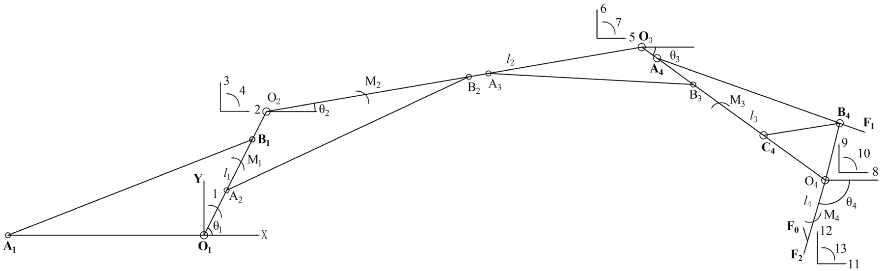
Simplified model of boom arm.
F 0 represents the impact reaction of the hydraulic breaking hammer and can be obtained by the following formula

In the above formula, F1 is the pressing force generated by the breaking hammer cylinder and F2 is the impact force generated by the piston of the breaking hammer. Assuming that the angle between the supporting arm O1O2 and the horizontal line is θ1, then

In Figure 3, M1, M2, M3, and M4 are rotational moments of the hydraulic cylinder added to three arms and one hammer, respectively. l1, l2, l3, and l4 are the lengths of three arms and one breaking hammer, respectively. θ1, θ2, θ3, and θ4 represent the pose coordinates, respectively. And, 1–13 indicate possible displacement numbers.
Based on the equivalent finite element, during which the methods of equivalent mass and equivalent force system are applied, the boom arm can be divided into four units of l1, l2, l3, and l4, and then, each unit is split into two nodes in the generalized coordinates. Based on the theory mentioned above, the mass and the inertia of a planar mass bar structure are symmetrically condensed at both ends and the equivalent mass matrix is achieved

The total equivalent mass matrix of a system, which reveals the relationship between the possible displacement nodes and the unit node coordinates of the system, is usually determined by the element mass matrix and the correlation matrix. The correlation matrix of the working device is
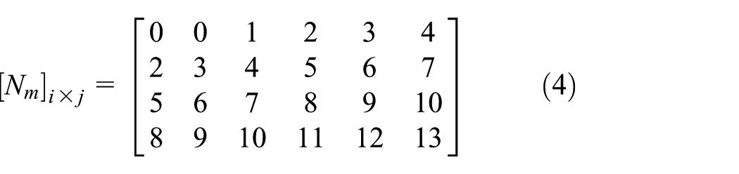
In the above formula, i denotes the unit node number, which ranges from 1 to 4; j indicates the system node number, which ranges from 1 to 13.
The total mass matrix of the working device can be obtained by combining formulas (3) and (4), as follows

The equivalent force of a working device is expressed as

In a linkage mechanism system, the possible displacement δR and the independent displacement δq satisfies the equation

in the generalized coordinates

the dynamic analysis equation is

Jacobian matrix T is


Yet, the pressing force F1 can be expressed as

When the hydraulic hammer works, the internal piston movement includes four steps: accelerated return, brake, impact travel and impact pause. According to its operational principle, the motion law of the piston can be expressed as 17

The front oil circuit and the rear chamber of the hammer piston are connected by the reversing valve during the impact, and the pressure is equal. Taking account of the pressure under the gas adiabatic condition and the volume change caused by the piston movement, it can be obtained as
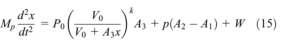
According to the differential principle, the energy of the piston can be expressed by the formula

Therefore, the piston has an impact energy that can be illustrated by the following formula

Based on the breaking principle of the hydraulic hammer, in order to truly reflect the vibration characteristics under the working conditions of a demolition robot arm, it is necessary to calculate the striking reaction force of the hammer in the process of crushing according to formulas (12) and (17).
Modal analysis of the boom arm
Establishment of simulation model
The boom arm is a crucial part of a demolition robot. As the performance and service life of the boom arm are determined by its stiffness, strength and dynamic characteristics, the resonance caused by the overlap of external excitation frequency and natural frequency of the boom arm will lead to the performance degradation and the service life reduction, therefore, the resonance should be avoided. To grasp the vibration characteristics and diagnose the vibration fault, the modal analysis of the arm is studied, and the results as the theoretical basis are provided for the structure optimization.
A three-dimensional model in SolidWorks is carried out. The model is necessary to be simplified appropriately on the premise of guaranteeing the main mechanical properties of the structure, because it is complicated. This process can not only reduce the workload of a computer but also will avoid the influence from small parts before being introduced into the simulation software.18,19 The main simplification processes include (1) removing pin shaft at the hinge joint of the pin shaft, (2) removing the oil delivery pipe and control valve of the hydraulic cylinder, (3) regarding the whole hydraulic cylinder and its oil, as an entirety, and (4) ignoring the trough pad in the breaking hammer facility.
The material for the boom arm is made of 45#quenched and tempered steel, whose Young’s modulus E = 2.09E+11 Pa, Poisson’s ratio μ = 0.269, density ρ = 7890 kg/m3; the material for breaking hammer rod is made of 42CrMo, whose Young’s modulus E = 2.12E+11 Pa, Poisson’s ratio μ = 0.28, density ρ = 7850 kg/m3. There are some diverse approaches to generate mesh, including tetrahedron/triangle, sweep, automatic, multi-zone, and hexahedron dominant/quadrilateral dominant. Since the default setting is usually too rough to satisfy the accuracy, the mesh element size is set to 12.0 mm in the details of “Mesh” to control the dimension, and the boom arm is divided into 198,502 units and 611,191 nodes. The average unit mass is 0.76923, which means it will contribute to obtaining more accurate results of the finite element analysis. 20
Modal analysis
Modal analysis, which is mainly used to analyze the natural frequency and modal shape of structures, is usually divided into two cases: free mode and constrained mode. The weak part of the structure can be confirmed via the natural frequency, the corresponding modal shape, and the parameters.21–23 Under the working conditions of a boom arm, the supporting arm and its hydraulic cylinder are hinged on the chassis through the respective mounting block. To accurately convey the working constraints, in Workbench, the cylindrical supports are imposed on the inner surface of the places where the supporting arm and the hydraulic cylinder are hinged on chassis, and the sinusoidal force of 200 kN is applied to the breaking hammer rod.
Generally, the low-order mode has a great effect on the damage to the structure. 24 Therefore, this article only investigates the first four-order natural modes of the analysis results, and the simulation results are shown in Table 1, which reveals the first four-order modal frequency and describes its mode shapes.
The first four modal parameters.
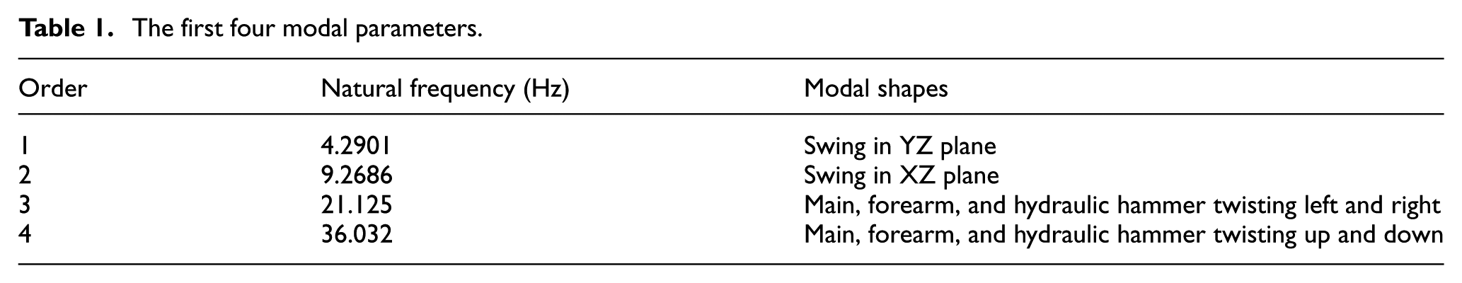
As the strike frequency of the hydraulic hammer is 8.33–16.67 Hz, the resonance may be caused under the second-order frequency. In order to ensure the safety and reliability of the structure, the modal characteristics of the second-order frequency should be analyzed. In the second-order frequency, the deformation cloud diagrams of the robot arm in the directions of X, Y, Z are shown in Figure 4.

Deformation cloud diagrams in (a) X direction, (b) Y direction, and (c) Z direction at second-order frequency.
They are easy to be found from the cloud diagram that the maximum deformation position in the X direction locates in the crushing hammer rod; and the maximum deformation position in the Y direction locates in two places: the installation block of the hydraulic crushing hammer and the hinge between the supporting arm and the main arm. Similarly, the pivotal position in the Z direction also appears in the breaking hammer rod. It clearly indicates that the deformation position in the Y direction is most likely to be destroyed during the operation.
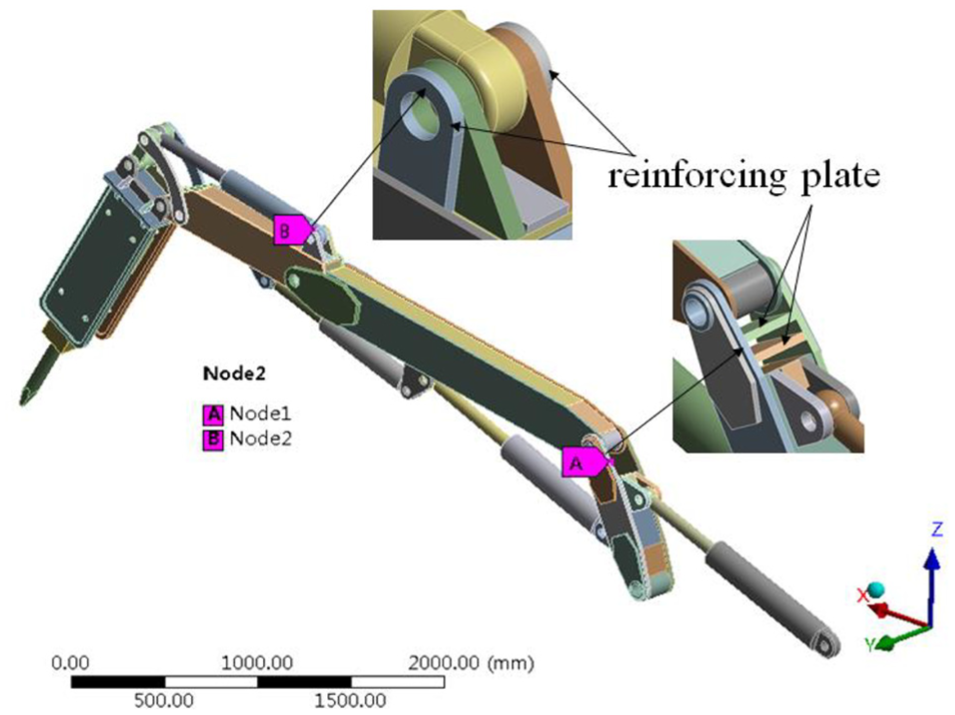
Node 1 is selected in the hinged position of the supporting arm and the main arm, and node 2 is selected in the mounting block of the hydraulic crushing hammer in ANSYS Workbench, as shown in Figure 5(a). The amplitudes and frequency curves of the two joints are obtained by analyzing their vibration characteristics under the action of the sinusoidal force, as shown in Figure 5(b).

(a) Selected nodes and (b) their amplitude–frequency curves.
According to the simulation results, in the second-order frequency, the vibration amplitudes of nodes 1 and 2 are 3.77 and 2.18 mm, respectively, in the Y direction, indicating that the structure or the stiffness of these two parts needs to be improved.
Optimized design of structure
The load is applied on the breaking hammer by the hydraulic cylinder directly, and the hydraulic cylinder mounting block bears the reaction force, so the block is easy to deform or damage. There are two common optimization methods in modal analysis:
Improving the layout of the structure to ameliorate dynamic characteristics: Import the modal analysis results into the topology optimization module in ANSYS Workbench; Set the three booms to the optimized area; Set the four hydraulic cylinders and the breaking hammer to the non-optimized areas. To obtain the maximum natural frequency of the structure, the constraint response is set to retain 60% and 50% mass in two different files, respectively. The simulation results are shown in Figure 6.
To improve the natural frequency of the structure, the red part is recommended to be removed according to the simulation principle. But the removal of the red part will affect the use of the dismantling machine, so this method is not applied to improve the structural dynamic characteristics.
2. Improving structural rigidity to ameliorate dynamic characteristics. The optimization should avoid interference with the original structure. Taking into account the movement form of the hydraulic cylinder of breaking hammer, two reinforcing plates on both sides of the mounting blocks are welded. Moreover, the 42CrMo is selected as the material to manufacture side panels and mounting blocks. The boom in the original structure is easy to vibrate in the Y direction when subjected to the transmitted force or torque, because the space between the two side panels is too large. Therefore, two reinforcing plates between two side panels are added to play a supporting role in reducing vibration in the Y direction, on the premise of no effect on rotation of the main arm. The optimized structure is shown in Figure 7.

(a) Optimized structure when (a) 60% mass is retained and (b) 50% mass is retained.
Optimized structure.
After simulating again, the results show that the mode shapes of the arm structure in first four-order natural modes have not changed, and the natural frequency is slightly increased, as shown in Table 2.
Natural frequency after optimization.

As shown in Figure 8(a), the maximum amplitudes in the Y-direction amplitude–frequency curve of nodes 1 and 2 are 0.30 and 0.47 mm, respectively, after optimizing the structure. Moreover, the maximum deformation position does not locate at node 1 or node 2 as shown in Figure 8(b).

(a) Amplitude–frequency curve and (b) deformation cloud diagram of the Y direction after optimization.
Based on the simulation, it can be found that the natural frequency of the structure is slightly increased by welding the reinforcing plates on both sides of the cylinder mounting blocks, changing the material of them, and using the stiffening plates between the two sides of the supporting arm plate on the basis of the original structure. Under the second order frequency, the maximum deformation displacement of the Y direction is obviously reduced, the vibration characteristic is significantly improved. Moreover, the structural stiffness is improved largely to ensure the safety and reliability for the structure.
Conclusion
In this article, a mechanical model of the three-segment demolition robot boom arm is established, the modal analysis of the boom arm is studied under the real working condition, and the following conclusions are obtained:
In the constrained state, the first four natural frequencies of boom arm are 4.29, 9.26, 21.12, and 36.03 Hz. The first two modes are mainly oscillating, while the latter two are torsion. The resonance is easily produced in the second-order frequency when the hydraulic breaking hammer works.
In the second-order frequency, the maximum deformation of the boom arm in the X direction appears in the breaking hammer rod; in the Y direction, the maximum displacements locate both in the mounting block of breaking hammer hydraulic cylinder and the hinge between the supporting and the main arms; in the Z direction, the maximum displacement also appears in the rod. It is noted that the structure and the stiffness of the boom arm need to be improved in the Y direction.
After optimization and simulating again, it can be found that the maximum amplitudes of nodes 1 and 2 in the Y direction are reduced from 3.77 and 2.18 mm to 0.30 and 0.47 mm, respectively, which are no longer the maximum deformation displacements. This article proves that the vibration characteristics of the structure are obviously improved. The result can provide a theoretical basis for the structure optimization of the prototype and a reference for the modal experiment.
Footnotes
Appendix 1
Handling Editor: Zhaojun Li
Declaration of conflicting interests
The author(s) declared no potential conflicts of interest with respect to the research, authorship, and/or publication of this article.
Funding
The author(s) disclosed receipt of the following financial support for the research, authorship, and/or publication of this article: This work was supported by the National Natural Science Foundation of China (no. 41672366) and the Fundamental Research Funds for the Central Universities (no. 292018093).