
Abstract
The development of the new energy automobile industry has driven the development of the tire industry, and the development of the tire industry has put forward higher requirements for the handling and storage efficiency of tires. In this paper, through the discussion of the new tire synchronous fixture, the double parallel four-bar mechanism is introduced. The mechanism has the advantages of horizontal extension and contraction, and avoids the deviation in the vertical direction. In order to be better applied to the handling and storage of tires and further applied in other fields, this paper obtains the relationship between rod length and stroke through the kinematic analysis of double parallel four-bar mechanism, establishes a compact structure size table of common size, and carries out practical application simulation. The accuracy of size is verified by mechanical simulation. Through the relationship established in this paper and the compact structure size table, we can quickly and easily find the appropriate size of the double parallel four-bar mechanism according to the demand. Through the study of its structural characteristics, we can easily find the scene where it can be applied, so as to promote the universality of the application of the double parallel four-bar mechanism.
Keywords
Introduction
In today’s world, automobile has become an indispensable means of transportation for people’s travel in recent years. As the research in the field of new energy vehicles continues to deepen, new energy vehicles have gradually become the mainstream means of transportation.1,2 With the emergence of research on new energy vehicle battery box, the industry has also developed rapidly on a global scale. The government actively formulates policies to promote the development of new energy automobile industry.3,4 At the same time, the technology of tire retreading and reuse has also triggered intense discussions in various countries. Both the development of new energy vehicles and the progress of tire retreading and reuse technology have stimulated the demand for tires in the global market, which has led to a rapid increase in global tire production.5,6
Although the global tire market has been rapid development, but the countries of the logistics and warehousing facilities are difficult to cope with the increase in demand for warehousing and transportation, tire transportation and warehousing has become a common problem faced by the tire industry in various countries, warehousing management in the new situation is facing many challenges. 7 From a comprehensive point of view, the tire industry production and logistics and transportation of several major problems is the tire transportation workload, the main logistics tools for forklifts, low efficiency, pollution, logistics management is complex. Especially in the current rapid development of warehousing and logistics and transportation industry in various countries, a variety of small and medium-sized enterprises in a large number of environments, tires and other goods facing the pressure of warehousing management is particularly prominent. 8 At present, although the warehousing system and management put forward a more advanced way, such as warehouse distribution network optimization, 8 Personnel motion trajectory prediction, 9 and handling robot fuzzy logic control, 10 Remote unmanned operation and human-computer interaction, 11 or by changing the warehouse to optimize the warehouse structure, 12 but the tire warehousing and logistics of the basic handling method is still relatively backward, mostly forklift or manual handling, now there is a handling machine for the tire synchronous fixtures, although the machine can be carried out through the handling, but the core structure of the rack and pinion mechanism, can only be carried out for a single tire handling, is still unable to better. The problem of low tire handling efficiency can’t be solved.
In this paper, the original tire fixture was structurally optimized through the final ideal solution method, and the method of using double parallel four-bar mechanism instead of the original rack and pinion mechanism was obtained, which greatly improved the tire loading and unloading as well as warehousing and transporting efficiency, and the key double parallel four-bar mechanism was studied in depth, and the kinematics model of the double parallel four-bar mechanism was established, and the structural optimization of the drive design of the double parallel four-bar mechanism was carried out, the compact structure size table was established, and the kinematic model of the double parallel four-bar mechanism was found. Compact structural dimension table was established to find the most lightweight, efficient and reasonable tire clamping mechanism, which provides a solution to the tire handling and storage problems in today’s world and at the same time provides a research basis for the application of this new type of mechanism in other scenarios to make it more convenient to be applied in a variety of scenarios.
Tire synchronizing clamp
Overview of existing tire clamp design
The original tire synchronous fixture, shown in Figure 1, includes a top plate and a bottom plate that are fixedly connected, with a central axis between the top plate and the bottom plate, and the central axis is connected to the outside through a rack and pinion mechanism, which achieves synchronous gripping of tires and overcomes the defect of tire fixtures that are difficult to synchronously locate. 13 Although the original tire fixture realizes the automatic grasping of tires, it can only grasp one tire at a time during handling, and is less efficient in loading and unloading tires in large quantities, which cannot better meet the needs of the rapid development of the world tire market and the substantial increase in the volume of tire transportation today.

Schematic diagram of the original tire synchronization fixture mechanism. 13
New tire synchronizing clamp
In order to better cope with the increased demand for tire transportation in today’s world, this paper draws out a new synchronous fixture for tires. As shown in Figure 2, the original rack and pinion transmission is changed to a double parallel four-bar mechanism transmission, and the movement of the connecting rod is driven by the movement of the nut driven by the ball screw, so as to realize the extension and contraction of the outer arm of the fixture. Double parallel four-bar mechanism brings a difference in the common four-bar mechanism transmission mode, this transmission mode makes the outer arm of the fixture has become the structure of the force rod, so that the outer arm extension to grasp the tire, thus improving the former rack and pinion transmission fixture can only grasp the shortcomings of a single tire, so that it can meet the growing demand for tire handling in today’s era, the new tire fixture core transmission mechanism is double parallel four-bar mechanism, this structure is the core transmission mechanism is the double parallel four-bar mechanism, this structure is the core transmission mechanism is the double parallel four-bar mechanism. The core transmission mechanism of the new tire fixture is a double parallel four-bar mechanism, this structure in the transmission through the movement of the rod to drive the movement of the outer arm, and at the same time to limit it, so that it can only move horizontally and cannot be moved in the vertical direction, to ensure the effect of transmission. The outer arm as the follower is the component that will be subjected to finite element analysis later on.

Structural schematic diagram and dimension diagram of the new tire synchronization fixture.
The material used by the institution is Q235 steel, with dimensions shown in Figure 2. The basic mechanical parameters of this institution are as follows: The Maximum gripping height is 2000 mm; The Maximum span is 806.2 mm; The Unilateral motion amplitude is 300 mm. The fixture structure after adding tire components is shown in Figure 3. The practical application demonstration of the fixture is shown in Figure 4.

Fixture structure after adding tire components.

Practical application demonstration of fixtures. 13
The double parallel four-bar mechanism transmission is the core of this fixture, due to its transmission method is relatively novel, and the current literature on parallel four-bar mechanism is mostly about the design of common crank-slider mechanism and crank-rocker mechanism, but the research on the double parallel four-bar mechanism is still relatively small. For example, Zhang et al. 14 investigated the comprehensive size optimization of four-bar linkage based on error feedback method. Sun et al. 15 studied the motion characteristics of space crank rocker mechanism based on Matlab. Zhang et al. 16 carried out an optimization algorithm-based scale synthesis study for motion generation of spherical link crank slider mechanism. Ahmadi et al. 17 and Ahmadi and Ahmadi 18 discussed the design of crank-rocker mechanism with optimal stroke, time ratio and transmission angle based on analytical game and optimal synthesis of crank-rocker mechanism with optimal transmission angle using genetic programming to obtain the desired stroke and time ratio problem respectively. Most of the above literatures have made a detailed study on crank-slider mechanism or crank-rocker mechanism, while there are fewer studies on double parallel four-bar mechanism in the known literatures. In order to make this new type of transmission mechanism more convenient to be applied on other scenarios, this paper will study the double parallel four-bar mechanism from the point of view of kinematics to investigate its motion law, so as to come up with the optimal structure under different application conditions, which will make this mechanism more convenient to be applied on other scenarios.
Kinematic analysis: Double parallel four-bar mechanism
In practical applications, it is not only required that the linkage mechanism can achieve the expected motion, but also that the mechanism operates flexibly and efficiently, which requires the mechanism to have good force transmission performance. The pressure angle (or transmission angle) is one of the important indicators for measuring the performance of force transmission in linkage mechanisms. In the mechanism shown in Figure 5, the expected motion of the mechanism is driven by the planar motion of the connecting rod to drive the motion of rod A1B1, while the main function of rod A2C2 and rod B2D2 is to restrict the motion of the rod rather than transmit it. Therefore, the mechanism shown in Figure 5 can be simplified as a four-bar hinge mechanism shown in Figure 7.
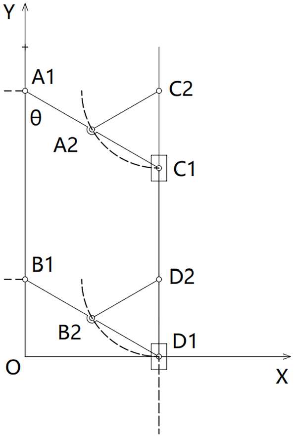
Kinematical diagrams.
Establish a coordinate system as shown in Figure 6 with C2 as the origin, C1 as the moving point, and rod A2C2 as the dynamic coordinate system. Let the length of rod A2C1 be equal to the length of rod A2C2, which is equal to L. Rod A2C2 rotates uniformly around point C2 at an angular velocity ω, and the angle between rod A2C2 and the horizontal direction is θ, θ = ωt.

Kinematic analysis diagram.
According to the velocity synthesis theorem, by decomposing the velocity along the coordinate axis, we can obtain:

That is:

By solving together, we can obtain: Ve = Vr = ωL, Va = 2ωLcosθ = 2ωLcos (ωt)
According to the acceleration synthesis theorem, by decomposing acceleration along the coordinate axis, we can obtain:
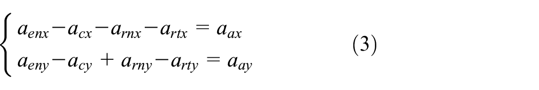
That is:

By solving together, we can obtain: art = −arn × cot θ = −arn × cot, aa = −(arn × sinθ + art × cosθ) =−(arn × sinωt + art × cosωt)
Based on the above kinematic analysis, the relationship between the velocity and acceleration of the mechanism and time can be obtained, laying the foundation for future research.
Analysis of pressure angle and transmission angle of double parallel four-bar mechanism
As shown in Figure 7, there is a four-bar linkage mechanism with a hinge. If the effects of inertia, gravity, and friction in the motion pair are ignored, the force F exerted by the driving crank C1D1 on the driven rocker A1B1 through the connecting rod A1C1 is in the direction of A1C1. The acute angle α between the force F and the absolute velocity Vc at the point of force application C is called the pressure angle. Now, the force F is decomposed along the Vc direction and perpendicular to the Vc direction to obtain the tangential component Ft and the normal component Fn. According to the geometric relationship in the figure, there are:


Motion diagram of four-bar linkage mechanism with hinge.
In the formula, Ft is referred to as the effective force component, which performs effective work on the driven component A1B1 and generates a rotational torque; Fn, known as the harmful force component, not only fails to perform effective work, but also increases the radial pressure in the motion pairs A1 and B1.
Due to the limitation of the allowable transmission angle, it is necessary to know the minimum value of the mechanism’s transmission angle during the design process. The following is a calculation method for the minimum transmission angle in a four-bar linkage mechanism. In Figure 7, for ΔA1B1C1 and ΔD1B1C1, according to the cosine theorem, there are:

Simultaneous solution yields:

The allowable value may vary depending on different devices and applicable scenarios. When designing a linkage mechanism, it is necessary to verify whether it meets the basic requirements of minimum transmission angle.
In ordinary hinge four-bar mechanisms, the design is usually carried out in the above manner, but in double parallel four-bar mechanisms, the situation is different. In a dual parallel four-bar mechanism, A1B1 = C1D1, A1C1 = B1D1. This leads to the result obtained by the above formula:
At this point, the minimum value of the transmission angle cannot be calculated simply by the rod length, and must be determined based on the conditions of practical application. Therefore, this article studies the influence of rod length and motion range on transmission angle through kinematic analysis of the double parallel four-bar mechanism, obtains the allowable transmission angle under different usage conditions, establishes a compact structure size table, and provides reference for the design and use of double parallel four-bar mechanisms in the future.
Double parallel four-bar mechanism of the two parallelogram short rod connected to form a right triangle, which also makes its transmission and ordinary four-bar mechanism is different. It is the active movement of the two connected sliders, driving the movement of the connecting rod, and finally to make the outer arm extend to reach the required stroke, while the outer arm is limited by the structure of the right angle triangle, its movement can only be horizontal extension and contraction, that is, only the horizontal direction of movement. Based on the study of the transmission angle in the literature,19–22 including the transmission quality of the crank rocker mechanism, change the input to affect the transmission angle, combined with the structural characteristics in the double parallel four-bar mechanism. Thus can be found, when L1 is used as the driving part to drive the follower L2 to move, the transmission angle γ is the angle between L1 and L2, the distance between L2 and its parallel bar is called X, X is the extended stroke of the double parallel four-bar mechanism. L1 and X can be regarded as a diagonal and a right-angled edge in the same right-angled triangle, the relationship between L1 and X as shown in equation (8). It can be established by the internal angle γ of the triangle.

The larger the transmission angle, the smaller the length of the connecting rod L1 required under the same stroke, but at the same time the size of the transmission angle also affects the range of the connecting rod movement, the smaller the transmission angle, the larger the range of movement of the connecting rod, connecting rod in the actual application of the broader is also higher, at the same time, the transmission angle needs to meet the minimum transmission angle, that is, it is necessary to be greater than the permissible transmission angle [γ] = 40°.
In summary, in the scope of meeting the transmission angle requirements, the larger the minimum transmission angle, the smaller the length of the connecting rod L1, the higher the transmission efficiency, but the corresponding range of motion will be reduced, so in the selection of the minimum transmission angle needs to be considered comprehensively in terms of the length of the rod and the range of motion (Figure 8).
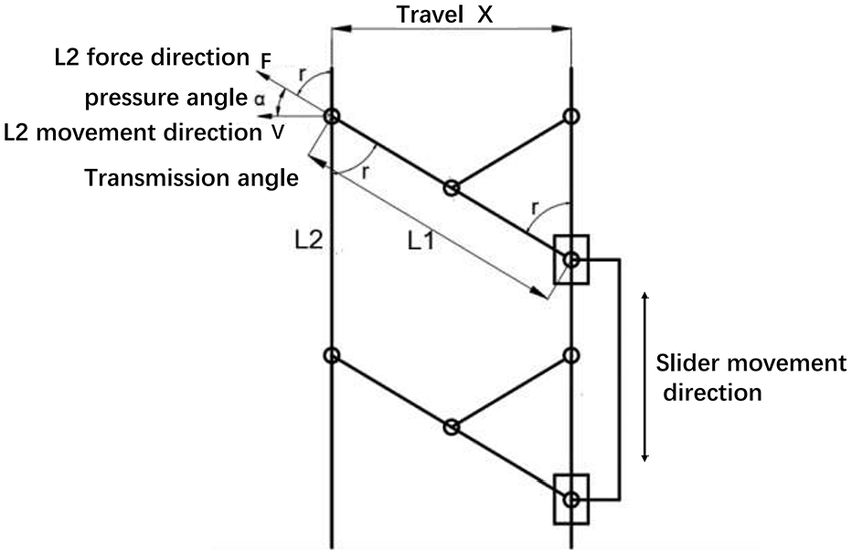
Structural sketch of double parallel four-bar mechanism.
Study of the range of variation of transmission angle with respect to rod length and stroke based on the above analysis
Based on the above analysis, in order to be able to choose more reasonably in the actual application, the relationship between the transmission angle and the length of the rod and the transmission angle and the range of variation of the travel will be investigated by the form of data analysis, respectively, under different travel requirements.
Correlation between transmission angle and bar length
In this study, we will be given different strokes while investigating the relationship between the required minimum transmission angle and the length of the rod when satisfying the given different strokes.
Equation (8):

Plot of bar length versus drive angle for different strokes.
By analyzing the curve Figure 9, we can conclude that the smaller the transmission angle is, the larger the length of the rod will be. At the same time, with the increase of the given stroke, the influence of the number of transmission angles on the length of the rod is also increasing
IMPact of transmission angle on range of motion
Mechanism of the movement of the change range that is the transmission angle from the minimum to the maximum change in the process of the rod extension distance of the change range, so set the change range of the rod for ΔL, the length of the rod for the

Due to the structure of the transmission angle at the maximum stroke is the maximum stroke, at this time the stroke is the length of the rod, that is, X′ =

In this study, we will investigate the relationship between different minimum transmission angles and the range of variation of mechanism travel for given different rod lengths and given different minimum transmission angles within a reasonable range.
Cite the formula (10):
Starting from a given fixed rod length, the relationship between the minimum transmission angle and the range of change of the mechanism’s stroke can be explored, as shown in Figure 10; as the rod length increases, the effect of the change in transmission angle on the range of change of the stroke is also expanding. And the smaller the transmission angle, the greater the effect of the rod length on the range of travel changes.
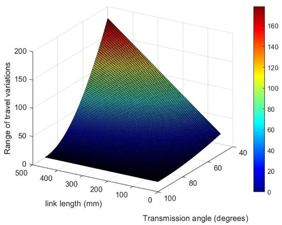
Relationship between the range of variation of the movement distance of the mechanism and the minimum transmission angle for different rod lengths.
Summary of kinematic analysis findings
Replacing the above rod length again with different maximum stroke requirements, the following conclusions can be drawn through the analytical study of the relationship between the transmission angle and the rod length under different stroke requirements, and the relationship between the transmission angle and the change of motion: the smaller the transmission angle, the larger the rod length, the smaller the transmission angle, and the larger its effect on the rod length; with the increase of the minimum stroke, the effect of the change of the transmission angle on the change of the range of the stroke is also expanding. And the smaller the transmission angle, the greater the effect of the minimum stroke on the range of travel changes.
Considering that the actual application should often be given priority to meet the needs of the actual stroke and range of motion, we generally need to find the range of transmission angle to meet the conditions of use in Figure 10, and then in Figure 9 to find the shortest transmission angle of the rod, then the transmission angle is to meet the actual needs of the premise of the structure of the most compact, the lowest cost of the transmission angle.
In order to facilitate the application of double parallel four-bar mechanism, this paper summarizes the conventional scope of application of double parallel four-bar mechanism, and establishes a compact structure size table, which can directly select the optimal transmission angle that can be used after determining the range of travel changes and minimum travel, so that the structure can directly check the table to obtain the optimal transmission angle required for other applications.
Practical application of dual parallel four-bar mechanism
Applying the double parallelogram mechanism to industrial scenarios requires comprehensive consideration of a series of practical factors. Therefore, this paper will take the application of the mechanism in the actual scenario of tire fixture as an example to analyze the mechanics of the mechanism and discuss its practical application.
Analysis of working conditions
Based on the actual application of tire handling fixture design a parallelogram fixture mechanism. The fixture structure to servomotor through the coupling drive ball screw, rotate at the specified rate, so that the double nut installed in the ball screw above the completion of the linear stroke, and then drive the parallelogram mechanism short side change angle, so as to complete the whole parallelogram expansion and contraction, change the minimum stroke mentioned in the previous section X, the bottom of the clamping jaws are equipped with a stop plate to prevent the fall, the mechanism is used in large warehouses such as tires and other disk loaded The mechanism is used in large warehouses for tires and other disk mounted parts clamping stacking and transfer, by the rationality of the mechanism from the perspective of the analysis of the feasibility of the actual industrialization, we need to the structure of the industrial application of the specifications of the design and stress simulation analysis of the actual application of the mechanism and to determine whether the fixture mechanism meets the strength requirements of the flowchart, as shown in Figure 11.

Flowchart for the application of double parallel four-bar mechanism.
Designing the fixture
Force analysis in fixture design
Our research aims to optimize the motion characteristics of tire clamping mechanisms. Therefore, the main load type considered is the dynamic load of tire handling during the normal operation of the clamping mechanism. Based on the actual requirements of the tire production and handling assembly line, we have selected the length of the L2 rod as 2.4 m, which is required to be able to clamp 6–7 tires weighing 25–40 kg. At the same time, considering safety margins and other aspects, we have set the actual load to 2750 N. Through our force analysis in 3, we can finally obtain the calculation formula for the force at the hinge connection of a single rod.
As can be seen from Figure 8, the force during the clamping up process mainly comes from the vertical component of the reaction force brought about by the internal linkage when the lever contacts the inner diameter of the tire and the bending stress brought about by the weight of the tire compressing the clamping jaws at the bottom of the lever, and in the proportional size of the overall structure, the length of the clamping jaws is much smaller than the length of the largest supporting lever, so we can approximate the gravity force mounted on the clamping jaws as the gravity force exerted on the supporting lever L2 The downward gravity force is applied to the support rod L2, and the movement of the L2 rod will cause the displacement of the short parallelogram rod connected by a pin. Due to the characteristics of the double parallelogram mechanism, the angle of inclination of the short bar becomes progressively larger. As the size of the tire to be clamped up gradually increases, its inner diameter will also expand. When the parallelogram mechanism extends to the maximum transmission angle that can be allowed, at this time the parallelogram in clamping up the largest support specifications of the tire on the outside of the support rod and the short side of the rod hinged at the place will produce a large stress, the load is the largest, the bending stress is the largest rod to study, the most test of the strength of the rod is up to standard.
Therefore, we choose to carry out strength analysis for industrial applications when the parallelogram fixture mechanism is at the maximum transmission angle. In view of the design of this fixture shell on the stroke has a specific limitation requirement (the free range of activity of the short rod by the size of the ball screw outside the protective shell slots), so this section does not consider the stress analysis of the anti-parallelogram, and only on the main bending stresses suffered by the rod L2 to be analyzed.
Transmission angle study based on force
In the previous section, we consider that the transmission angle has a minimum angle limitation of γ = 40°, and do not give the maximum transmission angle limitation, but in practical application scenarios there is an upper limit range of the transmission angle, based on the analysis of the working conditions, with the increase of the transmission angle of the articulation of the bar at the bending stress will also increase. The purpose of this study is to investigate the relationship between the transmission angle and the maximum bending stress on the bar under the same bar length conditions.
Equation (11):
From Figure 12 to get the vertical force of the bar in a certain transmission angle amplitude before the numerical curve with the expansion of the angle slowly increases until 80°–90° range there is a steep increase in the link, leading to the emergence of Figure 12(a) in the anti-L-shaped curve, and ultimately the magnitude of the vertical force of the bar is far beyond the range of the bar load bearing. Based on this point, the design of the upper limit of the amplitude of transmission angle change must be set before the turning angle, otherwise it will produce a greater test of the bearing capacity of the rod, and even damage the rod to produce fracture, affecting the stability of the fixture mechanism, and ultimately the comprehensive economic considerations, after a preliminary estimate to reset the upper limit of the transmission angle range of 80°, as shown in Figure 12(b) can be clearly observed in the force situation of the figure.

The relationship between the force of the rod and the amplitude change of the transmission angle: (a) full transmission angular amplitude and (b) pre-turn transmission angle amplitude.
Considering further the range of transmission angles, when the transmission angle changes, it will affect the force on the bar and the final stroke that can be achieved, and they have the following relationship: In the case of the same rod length, the larger the transmission angle, the greater the stroke that can be achieved, but the greater the bending stress at the same time. Under the given actual working conditions, the following formula can be given after analyzing the force of a single rod of 686 N.

By the formula to get a given rod under the transmission angle α limits the scope of change on the articulation of the vertical direction of the rod force and the impact of the stroke X1, α for the transmission angle, the range of 40°–80°, X1 for the current stroke, F1 for the vertical direction of the rod force, can be obtained as shown in Figure 13, the impact of the factors affecting the changes in the analysis of the chart:

Influence of the magnitude of transmission angle change on the force and travel variation of the mechanism.
Optimal cross-section shape and material selection
In industrial applications, the cross-section shape of fixture support bars should be considered from various influencing factors. In section “Analysis of working conditions,” we know that the main force of the bars is bending stress through the establishment of the formula, so we should consider more cross-section shapes with strong bending resistance. Different cross-section shapes have constant quantitative coefficient of bending resistance under the same area, among which, I-beam cross-section and groove cross-section have higher coefficient of bending resistance compared with circular cross-section and rectangular cross-section, and groove cross-section is chosen under the comprehensive consideration of the convenience of pin connection of the bar; on the other hand, the application materials of the outer support bar of the fixture are enumerated and analyzed, in order to find out that the parallelogram On the other hand, the material used for the outer support rod of the fixture is enumerated and analyzed, so that the parallelogram fixture mechanism can be designed to meet the strength standard, and Q235 steel is chosen as the optimal material for lightweighting and economic consideration to complete the design of the fixture.
Finite element analysis strength check
Boundary condition
The boundary condition of the finite element model is set to the pin connection form, which is set at the punching place of the two wings of the bar side change. Considering the actual strength and the pin specification, the punching place should be centered.
Unit system and material properties
The unit of finite element model adopts the national standard unit system. The material is assigned to structural steel, the Poisson’s ratio is 0.3, and the material density is 7.85 × 10⁻⁶ kg/mm3. The proportion limit of Q235 steel is about 196 MPa, and its ultimate tensile strength is 235 MPa.
Mesh subdivision
Application of automatic meshing, meshing accuracy of 10 mm
The application of force
The design applied stress direction that needs to be considered when checking the strength of the parallelogram fixture is at the bottom baffle of the bar. Because the bottom baffle is small in size relative to the overall bar, in order to facilitate consideration, we simplify this applied force to act at the end of the bar, and the direction is downward.
Further analyze whether the fixture mechanism can meet the application standards in practical scenarios. According to the assembly specifications of the pin shaft connection, the maximum deformation of the entire rod should not exceed 2 mm, otherwise it will affect the overall assembly effect and the operation of the fixture. Given the recommended value of the safety factor n = 1.5, the allowable stress of the fatigue strength of the bar structure [σ] = 352.5 MPa, and the type of cyclic load we use is constant load, we conduct high cycle fatigue test on it in the finite element analysis, and make its stress strain curve under different transmission angle design.
We calculate the maximum tire weight that the fixture can hold based on the length design of the main clamping rod and common tire thickness and weight specifications in the industry. Then, according to the force direction analyzed in our study section “Analysis of pressure angle and transmission angle of double parallel four-bar mechanism,” we comprehensively obtain the force at the hinge connection of the rod. We repeat this work for the force under different angles to obtain the comprehensive relationship between the transmission angle, stroke, and rod force shown in the chart, and import this relationship into finite element analysis for strength verification.
According to the force condition of the parallelogram mechanism, the main force members of the mechanical structure are simulated (based on the application requirements of the actual industrial scene, the travel data are obtained in Table 1 to define the length of the support member as 2 m, and the application length of other members can be calculated by the characteristics of the double parallelogram mechanism). As shown in Figure 14, the finite element analysis of the model is carried out to simplify the model structure, reduce the number of nodes and elements, and improve the mesh quality. We apply the load to the normal clamping condition of the member according to the actual force condition.
Table of compact mechanism dimensions for partial range of motion of double parallelogram mechanism table.


Strength check results: (a) total deformation, (b) equivalent stress, (c) fatigue life, and (d) fatigue damage.
The strength check results shown in Figure 14 can be obtained. The maximum deformation is 0.631 mm, the maximum stress is 43.529 MPa, and the maximum deformation and structural stress of the rod meet the requirements. In addition, through the stress analysis of the stress area of other members, the obtained values are far lower than the allowable stress value of fatigue strength. At the same time, the experimental data of the high-cycle fatigue strength cyclic test are exported to draw the stress-strain curve, the result is shown in Figure 15.
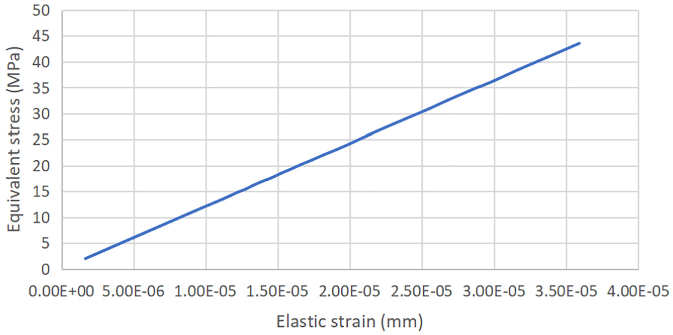
Elastic stress-strain curve.
Conclusion
In this paper, the kinematic analysis of the double parallel four-bar mechanism, which is the core mechanism of the fixture, reveals that:
(1) When the double parallel four-bar mechanism moves, the smaller the transmission angle required to satisfy the stroke, the greater the length of the bar. When the stroke is 50 mm, the maximum length of the bar is 77 mm, when the stroke is 250 mm, the maximum length of the bar is 288 mm, and when the stroke is 500 mm, the maximum length of the bar reaches 777 mm.
(2) The smaller the transmission angle of the double parallel four-bar mechanism is, the larger the range of stroke variation will be. At a stroke of 50 mm, the effect of the transmission angle on the range of stroke variation is 17 mm, at a stroke of 250 mm this effect reaches 90 mm, and at a stroke of 500 mm this effect expands to 178 mm.
(3) Guided by the general law derived from the above conclusions, the double parallel four-bar mechanism is put into practical application scenarios, and a series of mechanical analysis and strength calibration is carried out using ANSYS simulation, The stress data under different transmission angles are obtained by analyzing the stress change curve, and the stress distribution within the appropriate range is obtained on the premise of the actual fixture travel required by different specifications of tires. The data is substituted into the results of cyclic stress verification to verify whether the strength of the mechanism meets the safety standards. and the maximum stress value of σ is 33.803 MPa, which is smaller than the permissible stress of 352.5 MPa, and the maximum deformation of 0.39422 mm is also smaller than the maximum deformation, which proves the reasonableness of the structure with the data and provides a reasonable basis for the subsequent other practical applications. The data proved the reasonableness of the structure, and provided the theory and method for other subsequent practical applications.
Future outlook: Implications for industrial applications
In this paper, the double parallel four-bar mechanism is systematically analyzed, the laws of motion are obtained, and a compact structure dimension table applicable to the double parallel four-bar mechanism is established, which makes the application of the double parallel four-bar mechanism easier. Meanwhile, the feasibility of application in other fields is explored with distinctive application examples coupled with the rationality verification of the overall mechanism. It is hoped that this paper can promote and inspire the use of double parallel four-bar mechanism in various fields.
Footnotes
Acknowledgements
This research is also the result of receiving the support for the university innovation support project at Hoseo University, Korea and the 2024 provincial college student’s innovation and entrepreneurship training program project (Project: Liquid circulation cooling system for hydrogen storage tank of hydrogen energy vehicle), China.
Handling Editor: Divyam Semwal
Declaration of conflicting interests
The author(s) declared no potential conflicts of interest with respect to the research, authorship, and/or publication of this article.
Funding
The author(s) disclosed receipt of the following financial support for the research, authorship, and/or publication of this article: This research was supported by Regional Innovation Strategy (RIS) through the National Research Foundation of Korea (NRF) funded by the Ministry of Education (MOE) (2021RIS-004).
Data availability statement
The data that support the findings of this study are available from the corresponding authors upon reasonable request.