
Abstract
Numerical studies on the vane leading edge jet impingement cooling are conducted to analyzed the influence of the cylindrical ribs applied between adjacent jets. A one-way inlet coolant supply channel and a one-way exit semicircular target channel are connected through single array of 10 jet holes. The gradually accumulated cross flow greatly decreases the impingement heat transfer intensity at the target channel downstream region. Therefore, the influences of rib diameters (Dr/D = 0.25, 0.5, 0.75, 1.0) and three rib to jet distances (P/D = 1.2, 1.5, 1.8) are numerically studied to decrease the effect of the cross flow and increase the impingement heat transfer performance as well as the heat transfer uniformity. The Reynolds-averaged Navier-Stokes equations (RANS) method coupled with Realizable k–ε turbulence model are used to complete the numerical simulation, the numerical method is carefully validated. The pressure and velocity distributions are illustrated. The effects of ribs on the flow characteristics inside the semicircular target channel are discussed and three major vortical structures are captured and compared. The two heat transfer enhancement mechanisms which depend on the rib to jet distance are also analyzed in detail. Results indicate that, with the application of ribs, the area-averaged Nusselt number increases about 4.3%–11.3% and the impingement heat transfer is more uniformly distributed along the target channel axis. When pursuing a larger heat transfer enhancement and a larger performance evaluation criterion (PEC), a larger rib diameter coupled with a larger rib to downstream jet distance is preferred, the largest PEC enhancement is about 8.1%.
Introduction
For state-of-the-art engines, gas temperature at the turbine inlet has increased to more than 2000 K. To ensure the engine performance and the engine operating life, cooling strategies are commonly applied on the high temperature components. The vane leading edge suffers the direct impingement of hot gas, bears the highest heat flux and most complex flow field. Therefore, efficient and reliable thermal protection methods should be taken at the vane leading edge. In all the existing cooling methods, impingement cooling method can rebuild the boundary layer at the impingement region and enhance the heat transfer flux between coolants and target surface, hence the impingement cooling method is well-suited for the vane leading edge thermal protection.
Due to the complex flow features of the impingement cooling, the jet development process as well as the corresponding cooling performance is determined by a lot of influencing factors,1–3 such as the interference of adjacent jets, the cross flow scheme and its effect, the shape of both the jet hole and the target channel and the like. Forster and Weigand 4 explored the cooling performance of single jet array based on a curved target surface. They found that the cooling performance was decreased but the local heat transfer distribution was homogenized by the cross flow. Tepe 5 numerically investigated the impingement cooling performance of extended jet holes. Results showed that the extended jet hole structure is beneficial to the cooling performance on a semicircular target surface, a smaller jet to target distance was more preferred. Wright et al. 6 conducted an investigation on impingement cooling with varied jet positions. Pachpute and Premachandran 7 explored the impingement cooling under different jet Reynolds numbers, jet impingement distances and diameter ratios of target channel to jet hole. Heat transfer correlations were then presented accordingly. Tepe et al.5,8 came up with an extended jet structure and found the impingement cooling performance under the staggered jet arrangement is increased due to the decreased jet to target distance.
Limited by the coolant supply mode and the narrow space at the leading edge, there is only one outlet of the target channel, the cross flow is therefore concentrated in one direction. Since the cooling jet will be impacted and squeezed by the cross flow, the impingement cooling performance is significantly reduced. Lee et al. 9 indicated that the target surface heat transfer is reduced by the gradually accumulated cross flow under the multiple jet arrays configuration. Besides, on account of the enhanced interference between contiguous impinging jets and the locally enhanced turbulent transport, the local Nusselt number was firstly increased by the cross flow. Yang et al. 10 indicated that, affected by the vortical structures in both the axial and spanwise directions, the inverse temperature gradient is generated which results in the temperature nonuniformity. Besides, a larger jet Reynolds number and a shorter jet impingement distance yielded a better temperature uniformity. Otero-Pérez et al. 11 conducted a comprehensive investigation on multiple jet arrays cooling performance with large eddy simulations. The cross flow caused a jet deflection and reduced the Nusselt number peak value, the cooling performance in the areas less affected by the jet impingement was enhanced by the cross flow. Besides, adding turbulent fluctuations at the coolant inlet increased the effect of cross flow. Chen et al. 12 compared the impingement cooling performance among several cross flow schemes. With the application of film holes, more coolants were ejected out when the cross flow is developed along single direction, the cooling performance was then enhanced.
As the uneven distributed heat transfer performance caused by the one-way developed cross flow was undesirable, 13 many researchers conducted investigations to decrease the negative influences of the cross flow. Terzis et al. 14 found the negative effect of the cross flow could be adjusted by the jet hole diameter along the streamwise direction. An initially enlarged and then reduced jet hole diameter arrangement was also proposed by Ji et al. 15 Zhou et al. 16 came up with a jet array configuration with varied jet diameter based on three cross flow development stages to counter the negative effect of cross flow. The relation between the cross flow development and the jet diameter distribution was established. The non-uniformity coefficient among all impingement regions was successfully decreased from 9%–12% to 3%–4%. Ligrani et al. 17 tested the impingement cooling performance under different initial blowing ratios and contraction ratios. They proposed three competing phenomena that affect the target surface heat transfer. Chi et al. 18 came up with a novel impingement plate structure to direct the cross flow into the space between adjacent jets. As such, the impact intensity of the cross flow on the jet flow was impaired, the target surface heat transfer was also more uniformly distributed with optimum coolant consumption.
For the past few years, rib structures were also applied to diminish the negative effects of the cross flow and increase both the cooling performance and the target surface heat transfer uniformity. He et al. 19 applied several kinds of cross flow diverters to obstruct the cross flow development with the cost of increased friction losses. The influences of the diverter location and dimension were also studied. Salem et al.20,21 applied cylindrical, rectangular and ribbed diverters to remove the unfavorable effects of the cross flow. The Nusselt number was found to increase about 6.6%–12%, but the friction factor was increased about 9.9%–24.3% at the same time. He et al. 22 applied a corrugated target surface for a better impingement cooling performance. Madhavan et al. 23 used U-shaped ribs to protect the cooling jets from being impacted by the cross flow. There was about 9%–15% enhancement in heat transfer performance under a fixed pumping power. Ren et al. 24 experimentally investigated the effects of toughened target surface and found the near wall mixing is enhanced and the turbulence intensity is increased due to the reconstructed viscous sublayer. Yalçınkaya and Durmaz 25 performed numerical studies to analyze the effect of the extended jet nozzle on the cooling performance on a rib-roughened curved target surface. Rectangular cross-sectional V-shaped ribs were applied. The effects of rib height and rib angle were also studied. Based on the numerical results, the heat transfer performance as well as the heat transfer uniformity was increased. The highest thermal performance criterion was obtained under the rib height of Hr/d = 0.2 and the jet nozzle extend distance of G/d = 2.0. Kim et al. 26 experimentally and numerically compared the negative effect of the cross flow of the castellated jet impingement with and without rib structures on the target surface. The influence of jet spacing and jet impingement distance were also studied. Results showed that, due to the increased target channel cross-sectional area, the pressure drop inside the target channel was decreased. However, the rib structures on the target surface yielded little effects on the heat transfer performance. Fu et al. 27 applied W-shaped micro-ribs to reduce the effect of the cross flow and enhance the impingement cooling performance. The results showed that the ribs can separate the cross flow and reduce the effect of the cross flow, the longitudinal vortex generated by the cross flow could further enhance the convective heat transfer. The highest heat transfer enhancement was about 39.7%–48.9%. Fathi and Nejat 28 proposed an impingement cooling configuration in which two rows of ribs were established between adjacent impingement regions. The conjugate cooling performance was sensitive to the rib location and when the ribs were perpendicular to the cross flow, the overall cooling effectiveness was further increased. Shukla et al. 29 investigated the flow and heat transfer characteristics of impingement cooling on a surface covered with detached ribs based on the large eddy simulation method. Results showed that, the heat transfer was enhanced near the clearance between the ribs and the target surface due to the increased velocity and turbulence.
Most of the previous studies put the ribs in front of the impinging jets to decrease the influence of the cross flow. However, by applying the rib structure, the flow features inside the target channel become more complex and the flow losses are also enhanced. Therefore, it is important to conduct a comprehensive investigation on the influencing mechanism of ribs under different rib to jet distances and rib dimensions. Thus, this paper aims to find out a more rational layout of the rib structure to gain a better impingement cooling performance and a more uniformly distributed heat transfer on the target surface. To achieve this goal, numerical studies are conducted inside a simplified leading edge target channel under three jet to rib distances and four rib diameters. The impingement cooling model without applying ribs is used as a benchmark case for the convenience of the comparison. The major vortical structures coupled with pressure and velocity distributions are illustrated to reflect the cross flow development and the effects of ribs. The heat transfer enhancement mechanisms by applying ribs between adjacent jets are then analyzed accordingly.
Numerical method
Simplified leading edge impingement cooling model
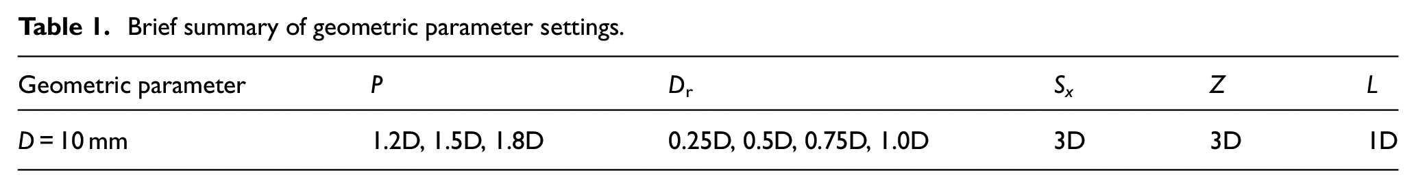
The simplified geometry of the leading edge impingement cooling is shown in Figure 1. A half domain numerical structure is applied to reduce the grid quantity. The cooling air impinge into the semicircular target channel successively through 10 jet holes, and the jet diameter is D = 10 mm. The length of impinging hole L, the axial distance between adjacent jets Sx and the jet impinging distance Z are 1D, 3D and 3D, respectively. The target channel radius is 3D. An effective cooling region between the target surface centerline and 75° line is defined to more reasonably reflect the leading edge impingement cooling performance. To better show the computational domain used in this study, a 3D view is also provided as a supplement.

Simplified impingement cooling geometry at vane leading edge.
Cylindrical ribs are added in front of each jet hole (except the first jet hole as there is no upstream cross flow) to decrease the influence of upstream cross flow on downstream cooling jet. As shown in Table 1, the influences of the jet to rib distance P (from the centerline of a jet hole to the centerline of an adjacent upstream rib) and the rib diameter Dr are investigated. Since a too small jet to rib distance or a too large rib diameter will excessively affect both the jet development process and the boundary layer reconstruction process after jet impingement, only three jet to rib distances (1.2D, 1.5D, 1.8D) and four rib diameters (0.25D, 0.50D, 0.75D, 1.0D) are applied in this paper. Besides, to facilitate the comparison among different cases, the impingement cooling geometry without applying the ribs (Dr = 0) is selected as a benchmark case.
Brief summary of geometric parameter settings.
Governing equations
The steady states governing equations that describe the incompressible flow inside the target channel are written as follow
Continuity equation

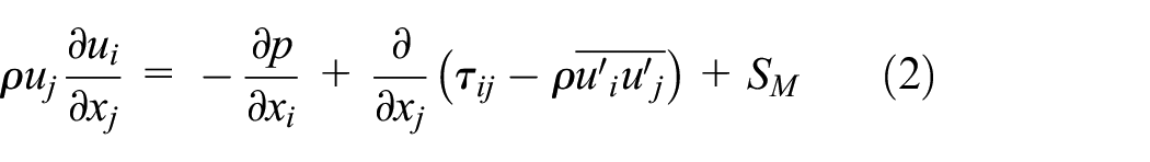
Momentum equation
Energy equation

where ui and uj are the time mean velocity,
Numerical boundary condition settings
The numerical boundary conditions as listed in Table 2 are based on Yang et al.’s30,31 experimental work. The major dimensions (D, L, Sx, Z) of Yang’s experimental model are all same with that of the numerical model studied in this work. The average jet Reynolds number of 10 jet holes (with the characteristic length of D) is 15,000 and the relevant total mass flow rate at the inlet is 1.225 × 10⁻² kg·s−1 with a turbulence intensity of 1%. The coolant temperature at inlet is Tc,in =348.15 K, the temperature on all target channel surfaces is fixed as Tw = 419.15 K, the surfaces of jet holes and coolant supply channel are adiabatic. The constant static pressure condition is applied at the target channel outlet with Pout = 0.1 MPa.
Boundary condition settings.

Grid independence analysis
The hexahedral structured grid is used to segment the fluid domain for all impingement cooling structures with ICEM 2023. Figure 2 shows the meshing details under p = 1.2D and Dr = 0.5D. The boundary layers are applied on all wall surfaces with a stretching ratio of 1.1, y+ < 1.0 is guaranteed and the layer number is about 24. To enhance the computational accuracy, outer O-blocks as well as the near edge mesh refinement is applied around the cylindrical ribs and jet holes. To ensure a convergent computing result, the calculation ends when the residuals of both the continuity and velocity equations fall below 10−4. SIMPLEC scheme is used for the pressure-velocity coupling, second order upwind scheme is applied for the spatial discretization.

Meshing details.
Grid independence studies are then conducted based on the calculated Nusselt number along the centerline of the target surface. The Nusselt number is written as

where qw is the heat flux, λ is the coolant thermal conductivity under Tc,in. Figure 3(a) shows the predicted result under p = 1.2D and Dr = 0.5D. The NuD curve predicted by the 2.5 million grids is significantly different from those predicted by other grids, especially at the impingement region and at the downstream region of ribs. With the increase of the grids number, the predicted NuD curve gradually converges. The NuD at impingement regions predicted by the 5.0 and 7.5 million grids differs about 5%, and the difference is less than 0.2% between 7.5 and 10.0 million grids. Therefore, the 7.5 million grids are selected to conduct the subsequent numerical investigations. About 7.5 million grids are also selected for other cases according to the predicted centerline NuD distribution which is not shown any more. GCI error 32 of the selected grids is then analyzed to further ensure the calculation accuracy, GCI error is defined as
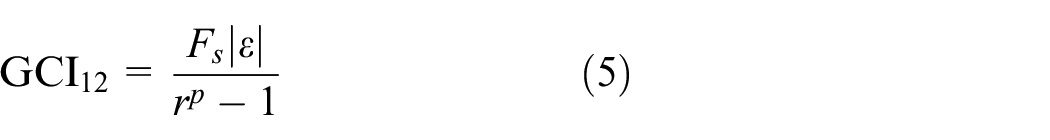
where the safety factor Fs and the grid refinement ratio r are 1.25 and 2, respectively. ε is the relative error which is written as

where f1 and f2 are the predicted value under the relevant normalized grid spacings, the convergence order p is then calculated as


Grids independence analysis: (a) predicted centerline NuD distribution and (b) predicted area-averaged NuD.
The Richardson extrapolation of the predicted result is then written as

Figure 3(b) shows the area-averaged Nusselt number
Applicability analysis of turbulence model
Numerical solution is obtained by using a steady approach of Reynolds-averaged Navier-Stokes equations (RANS) method in commercial software Fluent 2023. Turbulence models are firstly validated by comparing predicted results and the experimental data from Yang et al.’s30,31 work in which the same boundary conditions are applied.
Figure 4(a) shows the predicted spanwise-averaged Nusselt number (

Numerical model validation (concave target channel): (a) spanwise averaged NuD and (b) NuD contour.
The experimental work (5, 5, 3) by Fechter et al. 35 is used to further ensure the applicability of Realizable k–ε turbulence model. Figure 5(a) shows the NuD value along the centerline. SST k–ω turbulence model again overestimates the impingement heat transfer intensity, Realizable k–ε generally makes a better prediction. Figure 5(b) suggests that the Realizable k–ε turbulence model could better reproduce the NuD distribution. Consequently, Realizable k–ε turbulence model based on the RANS method is selected to conduct numerical studies on the impingement heat transfer performance under the effect of cylindrical ribs applied between adjacent jets.
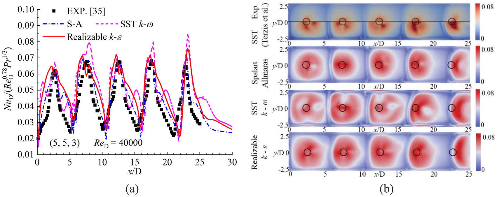
Numerical model validation (rectangular target channel) 35 : (a) NuD distribution along centerline and (b) NuD contour.
Results and heat transfer enhancement mechanism analysis
Performance evaluation criterion comparison
The jet mass flow rate distribution is firstly determined since its great influences on the flow development process and the impingement intensity. The mass flux ratio Gc/Gj is selected to show the cross flow development process which is defined as

where mc, i is the cross flow mass flow rate in front of the ith jet, mj, i is the jet mass flow rate through the ith hole. Aj and A are the cross section area of the jet hole and the target channel, respectively. Figure 6 shows the Gc/Gj ratio under p = 1.2D and 1.8D. The results of p = 1.5D are not shown here anymore since the final conclusion does not change. Gc/Gj of first hole is 0 since the target channel has only one exit. With the continuous impingement of downstream jets, the cross flow gradually accumulates along target channel axis. Results show that all Gc/Gj curves are almost the same before the seventh jet. The largest deviation appears at the last jet, however, the relevant deviation of the jet mass flow rate is still less than 4.0% among all cases. Therefore, the coolant mass flow rate distribution through ten jet holes and the basic cross flow development process are not obviously affected by either the rib locations or diameters, the flow features and the impingement heat transfer with ribs established between adjacent jets can be fairly compared under different P and Dr.

Comparison of the mass flux ratio: (a) p = 1.2D and (b) p = 1.8D.
Table 3 compares the total pressure drop ΔPt between the inlet and outlet of the numerical model. Generally, a larger jet impingement intensity leads to a larger ΔPt. In the benchmark case of Dr = 0.00D, ΔPt is about 1014 Pa. With the increase of Dr, the interference between ribs and cross flow becomes stronger, the impinging jet is less affected by the cross flow, ΔPt increases about 5.7%–9.1% from Dr = 0.00D to Dr = 1.00D. Under the same Dr, ΔPt is not heavily affected by P when Dr < 0.75D. It suggests that the relative location between ribs and adjacent jets has small effects on the flow features inside the target channel under a small Dr. However, when Dr = 0.75D, ΔPt increases a lot with the increase of P. When Dr = 1.00D, ΔPt under p = 1.8D is much larger than that under p = 1.2D and 1.5D. It suggests that the main flow features are also heavily affected by the rib location under a larger Dr.
Total pressure drop under different P and Dr.

Table 4 shows the area-averaged Nusselt number

Area-averaged Nusselt number.

The Performance Evaluation Criterion (PEC) 8 is then caluculated to make an overall evaluation of different cases, PEC is defined as

where
Comparison of performance evaluation criterion (PEC).

Flow features under the effects of RIBS
With the application of ribs, the flow development process of impingement cooling become more complex. As the vortical structures play a vital role in determining the flow features and the heat transfer performance,36,37 the flow development and the vortical structures are detailed illustrated and compared in this section to find out the heat transfer enhancement mechanism of applying ribs.
Figure 7 shows the vortical structure distribution in three cases under p = 1.5D (2000 s−1 swirling strength 38 ). For the benchmark case of Dr = 0.0D, two major vortical structures are clearly captured. The first one located at the bottom of the target channel is classified as a-type vortical structure. This kind of vortical structure is induced by the interference between surface flow and cross flow and is more apparent at the upstream region (also see Figure 8). The second one extended from the jet hole outlet is classified as b-type vortical structure. This kind of vortical structure is induced by the interference between cooling jet and cross flow and is less obvious at the upstream region (also see Figure 10). With the application of ribs, both those two kinds of vortical structures become less obvious which indicates that the interferences among cross flow, surface flow and cooling jet is diminished. Besides, a horseshoe shaped vortical structure occurs around the bottom side of ribs and is classified as c-type vortical structure. This kind of vortical structure is induced by the interference between ribs and cross flow and is more apparent at the downstream region (also see Figure 9). With the increase of Dr, the development of the first two types of vortical structures is more disturbed, but the c-type vortical structure is more apparent. As the influence of P on the vortical structure distribution can not be clearly distinguished, the results under p = 1.2D and 1.8D are not shown any more.

Comparison of vortical structure distribution with a swirling strength of 2000 s−1 (p = 1.5D): (a) benchmark case, (b) Dr = 0.5D, and (c) Dr = 1.0D.

Static pressure contour and surface streamline on the symmetry plane: (a) benchmark case, (b) p = 1.2D, and (c) p = 1.8D.

Static pressure contour and surface streamline on the plane of y/D = 0.5.
Figure 8 shows the comparison of Ps distribution as well as the surface streamline on the symmetry plane among different cases. Once the coolant impinges on the target surface, the coolant diffuses in all directions and the surface flow is formed. The surface flow toward the upstream direction collides with the cross flow, and a fountain like flow39,40 is formed. A pair of a-type vortical structures are generated aside the fountain like flow. As the cross flow accumulates gradually along the channel axial direction, the impinging jet is squeezed and bent, the surface flow that toward the upstream direction is weakened, the fountain like flow and the a-type vortical structure die down, the impingement intensity of cooling jet is then gradually weakened along the channel axis.
With the application of cylindrical ribs, the development processes of both the cross flow and the surface flow are disturbed and obstructed. Under p = 1.2D, the cross flow is obstructed when it is about to impact the downstream jet, the direct flow interference between the surface flow and the upstream cross flow is significantly weakened especially when Dr > 0.25D, the a-type vortical structure is then generated aside the ribs instead of the fountain like flow. With the increase of Dr, the cross flow development is more obstructed, the impinging jet is then less bent by the cross flow which suggests a larger jet impingement intensity, both ΔPt and
It can be concluded that the heat transfer enhancement mechanism is influenced by the rib locations. Firstly, the effect of cross flow is more diminished by ribs when the ribs are closer to their downstream jets. Secondly, the surface flow is more forced toward the upstream direction to counter the impact of cross flow when the ribs are closer to their upstream jets. When p = 1.5D, it’s a combination of those two mechanisms, so the relevant results are not discussed any more.
To further explain those two heat transfer enhancement mechanisms, Figure 9 shows the static pressure contour and surface streamline on the horizontal plane of y/D = 0.5. For the benchmark case, there are two high Ps regions near each jet hole. The upstream one is caused by the flow collision, the downstream one represents the core region of the impinging jet. The low Ps region between those two high Ps region is caused by the a-type vortical structure. As shown in the surface streamline, due to the flow collision, part of the upstream cross flow is forced to expand laterally, the downstream cooling jet is then less influenced. With the application of ribs, the cross flow is separated and the c-type vortical structure is generated behind the ribs. When Dr = 0.25D and p = 1.2D, only a small amount of the cross flow can recover back to the center after being separated, the flow collision occurs much closer to the upstream rib, the low Ps region becomes more obvious. When Dr = 0.25D and p = 1.8D, more cross flow can recover back to the center after being separated, the low Ps region is more similar with that of Dr = 0.0D. With the increase of Dr, the flow features are more complex and the pressure loss becomes larger. As the target channel outlet pressure is fixed, the global pressure level inside the target channel is then increased about 50–80 Pa. When Dr = 1.00D and p = 1.2D, the cross flow can hardly recover back to the center after being disturbed, the a-type vortical structure is generally formed when the surface flow impacts the upstream rib. When Dr = 1.00D and p = 1.8D, it is evident that the impinging jet is squeezed by the downstream rib, and the static pressure ahead of each rib becomes much higher, the large reverse pressure gradient pushes more surface flow toward the upstream direction to counter the impact of the cross flow.
Figure 10 shows the static pressure contour and surface streamline on several y–z planes. The development process of the b-type vortical structure along the channel axis can be well reflected by the surface streamline. Refer to the film cooling investigations with inclined coolant injection, 41 the b-type vortical structure may be analogous to the anti-kidney vortex by which the flow losses and the heat convection outside the impingement regions are all increased. As the flow interaction becomes much stronger along the channel axial direction, the b-type vortical structure becomes more pronounced until it occupies the entire channel. With the application of ribs, the development of the cross flow is disturbed, the development of the b-type vortical structure and its effect on the target surface heat transfer are then impaired especially under a larger Dr.

Static pressure contour and surface streamline on several y–z planes: (a) benchmark case, (b) p = 1.5D, Dr = 0.5D, and (c) p = 1.5D, Dr = 1.0D.
Figure 11 shows the tangential velocity distribution on the symmetry plane. The region where the velocity greater than 10 m·s−1 (except for the impinging jet occupied regions) can be regarded as the region where the b-type vortical structure is well developed. When p = 1.2D, the b-type vortical structure is not obviously influenced by ribs, the region where the velocity greater than 10m·s-1 occurs at the rear of the fifth jet under all Dr. However, when p = 1.8D, the b-type vortical structure is significantly hindered by ribs, especially under a larger Dr. This is because this anti-kidney shaped vortical structure is induced at the rear of the impinging jet, its development space is taken up when the ribs are located too close to the upstream jet. Besides, when Dr = 0.25D, the b-type vortical structure is not heavily influenced by the rib location. However, when Dr = 1.00D, a smaller P yields to a better development of this anti-kidney shaped vortical structure.

Tangential velocity distribution on the symmetry plane: (a) p = 1.2D, (b) p = 1.8D, (c) Dr = 0.25D, and (d) Dr = 1.00D.
Impingement heat transfer performance
Figure 12(a)–(c) show the spanwise-averaged Nusselt number

Comparison of
Figure 12(d) compares the

Comparison of
Figure 14 shows the NuD contours under different P. The starting location (red lines) where the high impingement heat transfer area (NuD > 110) disappears is marked. In the benchmark case, with the increased influences of the cross flow along the channel axis, the oval shaped high NuD region is gradually changed into a crescent shape, the impingement heat transfer deteriorates abruptly at the downstream of the fifth impingement region due to the overbent impinging jet. The heat convection outside the impingement region is increased due to the more accumulated cross flow and better developed b-type vortical structure. With the application of ribs, the high heat transfer area can last to a more downstream region as a consequence of the two heat transfer enhancement mechanisms. When p = 1.2D, due to the direct resistance of ribs, the impingement heat transfer is improved even under a smaller Dr. The shape of the impingement region at the target channel downstream area is more like a V-shaped boomerang with the increase of Dr. When p = 1.8D, more surface flow is forced toward the upstream direction, the flow collision intensity is enhanced, the impingement heat transfer improvement is more apparent under a larger Dr. The impingement region at the target channel downstream area is more like a fuller meniscus with the increase of Dr. The relevant result when p = 1.5D is somewhere in between. Besides, under all three P, the impingement region can be extended to a further downstream area than the benchmark case, the low heat transfer area between adjacent impingement region is then compressed. This phenomenon is more apparent under a larger Dr. Therefore, the

Comparison of NuD distribution on the target surface: (a) p = 1.2D, (b) p = 1.5D, and (c) p = 1.8D.
Conclusions
The impingement heat transfer enhancement mechanism of cylindrical ribs applied between adjacent jets inside a semicircular target channel has been numerically studied. The influences of rib diameter and rib to jet hole distance are also investigated. Major vortical structures coupled with pressure and velocity distributions are illustrated and analyzed to intuitively show the effects of ribs. The heat transfer characteristics is then discussed and compared accordingly. The key conclusions of this paper are listed as follows:
(1) With the application of ribs, the impinging jet is less affected by the cross flow at the cost of a more complex flow features inside the target channel, the total pressure drop increases about 5.7%–9.1%, the area-averaged Nusselt number increases about 4.3%–11.3% and the maximum Performance Evaluation Criterion (PEC) enhancement is about 2.1%.
(2) When pursuing a smaller flow loss, a smaller rib diameter coupled with a smaller rib to downstream jet distance are preferred. when pursuing a larger heat transfer enhancement and larger PEC, a larger rib diameter coupled with a larger rib to downstream jet distance are preferred.
(3) The heat transfer enhancement mechanism of applying ribs is affected by the rib to jet distance. Firstly, the effect of cross flow is more directly diminished by ribs when the ribs are closer to their downstream jets. Secondly, the surface flow is more forced toward the upstream direction to counter the impact of cross flow when the ribs are closer to their upstream jets.
(4) With the increase of rib diameter, the heat transfer performance at the target channel upstream region decreases gradually and the heat transfer performance at the target channel downstream region increases gradually. Thus, both the heat transfer performance and the uniformity of the heat transfer distribution are improved.
(5) The impingement region can extend to a further downstream area with the application of ribs, the low heat transfer area between adjacent impingement regions is then compressed, especially under a larger Dr. When the ribs are much closer to their upstream jets, the impingement heat transfer enhancement is more pronounced.
In this paper, the influencing mechanism of the location and diameter of the circular rib on impingement heat transfer performance is investigated, however, many factors, such as the effect of rib shape, target surface effusion hole, Reynolds number and so on, are not taken into considerations. Besides, a simplified semicircular leading edge model is used, the effect of actual vane structure and the heat conduction are also not studied. Thus, a more comprehensive study is still needed to investigate the influence of ribs to further verify its heat transfer enhancement mechanism as well as its practicability at the leading edge impingement cooling.
Footnotes
Appendix
Handling Editor: Ahmed Al-Sammarraie
Declaration of conflicting interests
The author(s) declared no potential conflicts of interest with respect to the research, authorship, and/or publication of this article.
Funding
The author(s) disclosed receipt of the following financial support for the research, authorship, and/or publication of this article: The research work was funded by the Young Elite Scientists Sponsorship Program by CAST (Program No. 2022QNRC001) and the Youth Fund project of Natural Science Foundation of Jiangsu Province (Funding No. BK20210301), Open Fund of Key Laboratory of Inlet and Exhaust System Technology of Ministry of Education (Funding No. CEPE2024013).