
Abstract
In this article, film cooling characteristics, especially the phenomenon of backflow for the straight turbine blade leading edge, are investigated. Shear stress transport k-ω turbulence model and structured grids are employed to assure the accuracy of the simulation, and the computational method is verified by the available experimental data. The influences of blow ratio, hole diameter, and the spacing between holes in each row are analyzed. The formation mechanism of backflow is discussed to prevent it from happening or relieve the degree of backflow, thereby to improve the cooling efficiency. The results showed that backflow can be avoided by adjusting the structure and the layout of film cooling holes. With increase in blow ratio, the cooling film becomes more obvious at first and then fades gradually for departing from the blade surface. The jet flow is influenced by the total pressure ratio between coolant cavity and surface of blade leading edge. Smaller film hole diameter and larger hole spacing makes it easier to eject coolant and form continuous film by slowing down the pressure in the cavity. Increasing ratio of hole spacing to hole diameter (p/d) can effectively prevent backflow, whereas larger p/d also makes the film coverage area smaller.
Introduction
Modern advanced gas turbines operate in temperature over the melting point of the blade to satisfy the needs of higher thermal efficiency and specific power output, which promotes the development of cooling techniques. Film cooling is an effective method to protect turbine blade or vane from thermal stresses. Relatively cold air from the compressor stages is ejected from holes and adheres to the blade surface, forming film and protecting the metal from the hot mainstream. Film cooling performance is difficult to predict because of the complex flow conditions along the blade surfaces in turbine engines. Film cooling is applied to nearly all of the external surfaces associated with the airfoils exposed to the hot combustion gasses such as the leading edges, main bodies, blade tips, and endwalls. The influencing factors of the film cooling performance mainly include the geometric parameters of the film holes and aerodynamic parameters, such as blow ratio, density ratio, mainstream velocity, and rotation speed.
The blow ratio is one of the most important factors on film cooling. Pedersen et al. 1 first studied the effect of blowing ratio on film cooling characteristics of a row of jet holes on flat plate. The experimental results show that the film cooling efficiency near the jet holes increases first with the increase in the blow ratio, then gradually begins to decrease after reaching a peak, and finally, the curve becomes flat. And, the density ratio is another important flow parameter. Pedersen et al. 1 gave experimental results with density ratios varying from 0.75 to 4.17 using the heat and mass transfer comparison method. When the density ratio is lower than 1, the cooling efficiency gradually decreases as the blow ratio increases. As the density ratio increases, the peak of cooling efficiency occurs at a higher blow ratio. With the same blow ratio, high-density jets are easier to maintain on the wall.
The shape of film cooling holes can affect the cooling effectiveness by changing the flow characteristic of jet. Researches on the structure of film cooling holes get more attention with the development of process technology. Goldstein et al. 2 found that the cooling efficiency at downstream area of the film cooling holes was significantly improved when the outlet of traditional cylindrical holes was extended to trapezoid, and the film still had a good attachment to the blade when the blow ratio was high. Sargison et al.3,4 investigated the flow and heat transfer characteristics of a new converging slot hole, and the results show that this kind of hole shape has higher cooling efficiency than the cylindrical hole and can greatly reduce the aerodynamic losses. Experimental studies by Dittmar et al. 5 and Mayhew et al. 6 have shown that compound angle holes can improve the cooling efficiency. Yuen et al. 7 and Yu et al. 8 studied the film cooling effectiveness and heat transfer characteristics with fan-shaped holes and diffusion-shaped holes, and the performance is better than conditions with cylindrical holes, especially under high blow ratio conditions. The effect of hole spacing and the film hole configurations have also been focused on. Liu and colleagues9,10 performed numerical simulation on the leading edge film cooling on a turbine vane model with two types of counter-inclined film hole row.
Considering the large curvature of leading edge, many researchers employ cylinder or semi-cylinder model to conduct experiments. Ahn et al. 11 experimentally investigated the influence of rotational speed, blowing ratio, and vortices on the film cooling effectiveness distribution at the leading edge region. Kim et al. 12 studied the flow characteristics using a cylindrical body with three different arrangements of injection holes. Lu et al. 13 studied the influence of hole compound angle and shaping using a blunt body with a semi-cylinder leading edge and a flat after-body. The results show that the additional compound angle in the transverse direction for rows of holes significantly improved the cooling effectiveness. Ou and Rivir 14 studied the film effectiveness and heat transfer coefficients on a large-scale symmetric circular leading edge with three rows of film holes. They found that the turbulence intensity has an attenuation on film effectiveness. YJ Kim and S-M Kim 15 investigate the film cooling performance using five different cylindrical body models with various injection holes. The results show that the laidback hole provides better film cooling performance than other holes. Liu et al.16,17 also experimentally studied the film cooling performance of cylindrical holes and laidback holes, which shows the same results with Ahn et al. 18 and Elfert. 19
The numerical simulation method develops rapidly and compensates the lack of experimentation. Tyagi and Acharya
20
calculated the dual-hole film cooling model with different hole spacings and studied the mutual influence of two jets at the downstream of the hole in the incompressible flow state. Guo et al.
21
and Renze et al.
22
added a coolant cavity in the model and obtained a more accurate turbulent boundary layer on the premise of a pre-collected stable jet, and explained the phenomena in unsteady flow field with vortex structure. Lakehal et al.
23
conducted numerical simulation on the film cooling on the leading edge with standard
As can be seen from the above summary of the literature, the previous work about turbine blade leading edge film cooling focused on the influence of the effect of flow conditions, the shape of film holes, and the film hole configurations. But, relatively less studies are based on actual blade profile. Symmetric cylindrical or semi-cylindrical models can simulate the large curvature of leading edge to some extent, but the pressure side and suction side of actual blade are asymmetric. More in-depth researches are required to further develop the potential improvement of the film cooling on the leading edge. In addition, there is little research about the causes and influence factors of backflow phenomenon. In this article, the film cooling behaviors on the leading edge of a straight turbine blade with three rows of film holes is numerically studied in static state. The study covers the effects of the diameter, spacing, blowing ratio on the film coverage effect, the outflow of the jet, the development process of the film, and the distribution of the film cooling efficiency. The mainstream backflow phenomenon is noticed and the formation mechanism is discussed, which can be a helpful reference for turbine blade designers. Research shows that the backflow can be avoided or alleviated by adjusting the spacing and diameter of film holes under the same inlet conditions, and the cooling efficiency can be improved consequently.
Computational method
Computational method
The high-pressure turbine rotating blade model used in this article is a straight blade, which is based on the cross section at 1/2 height of an actual turbine blade, as shown in Figure 1. The chord length of the blade is 41 mm, the axial chord length is 37.3 mm, the blade height is 70 mm, and the distance from the center of the blade to the center of rotation is 350 mm, that is, R = 0.35 m. The installation angle is 59.5° and the flow inlet angle is 45°. The diameter of the semi-cylinder on the leading edge is 4 mm.
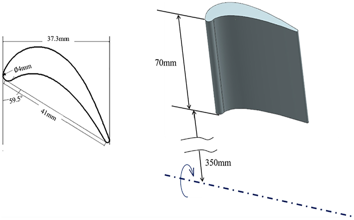
Diagram of blade model parameters.
Three rows of film cooling holes are located at stagnation line (0°) and ±45° on either side of the leading edge model on the leading edge as shown in Figure 2. The inclination of the holes
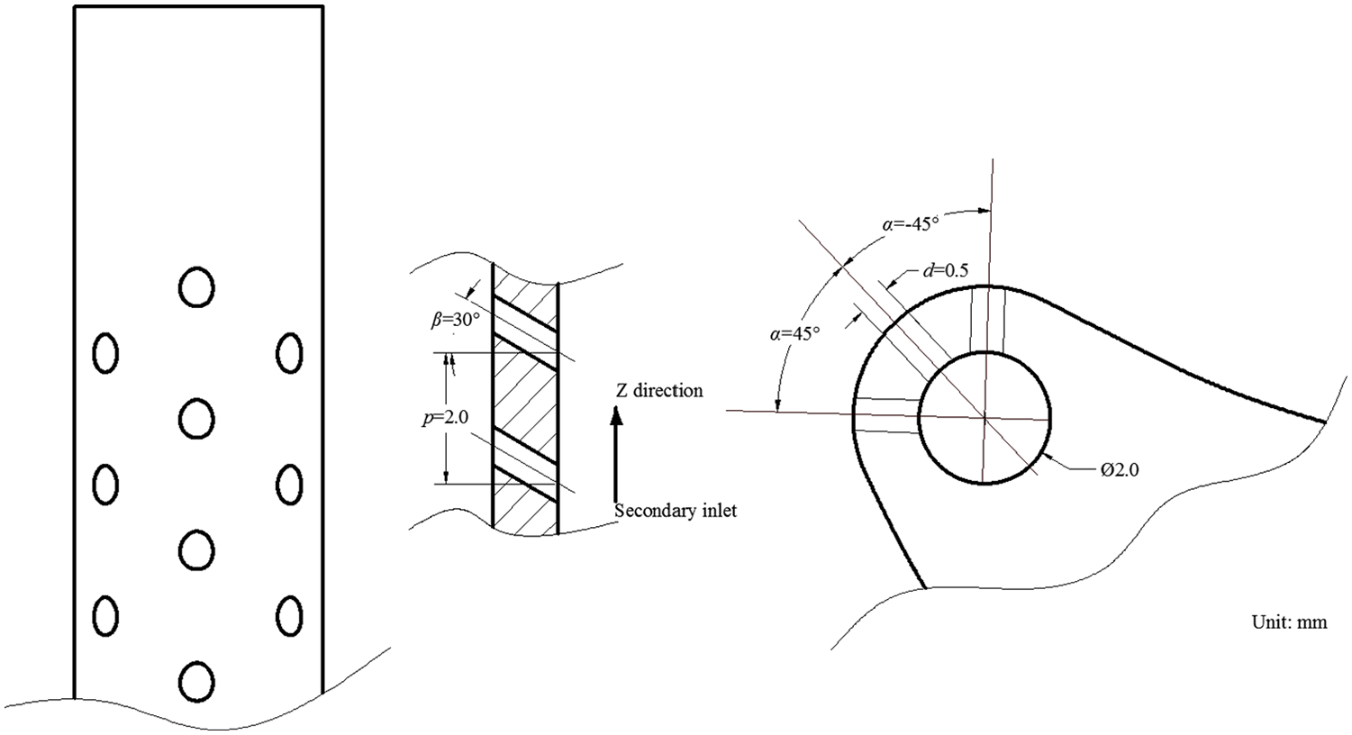
Schematic diagram of film hole distribution and geometric parameters.
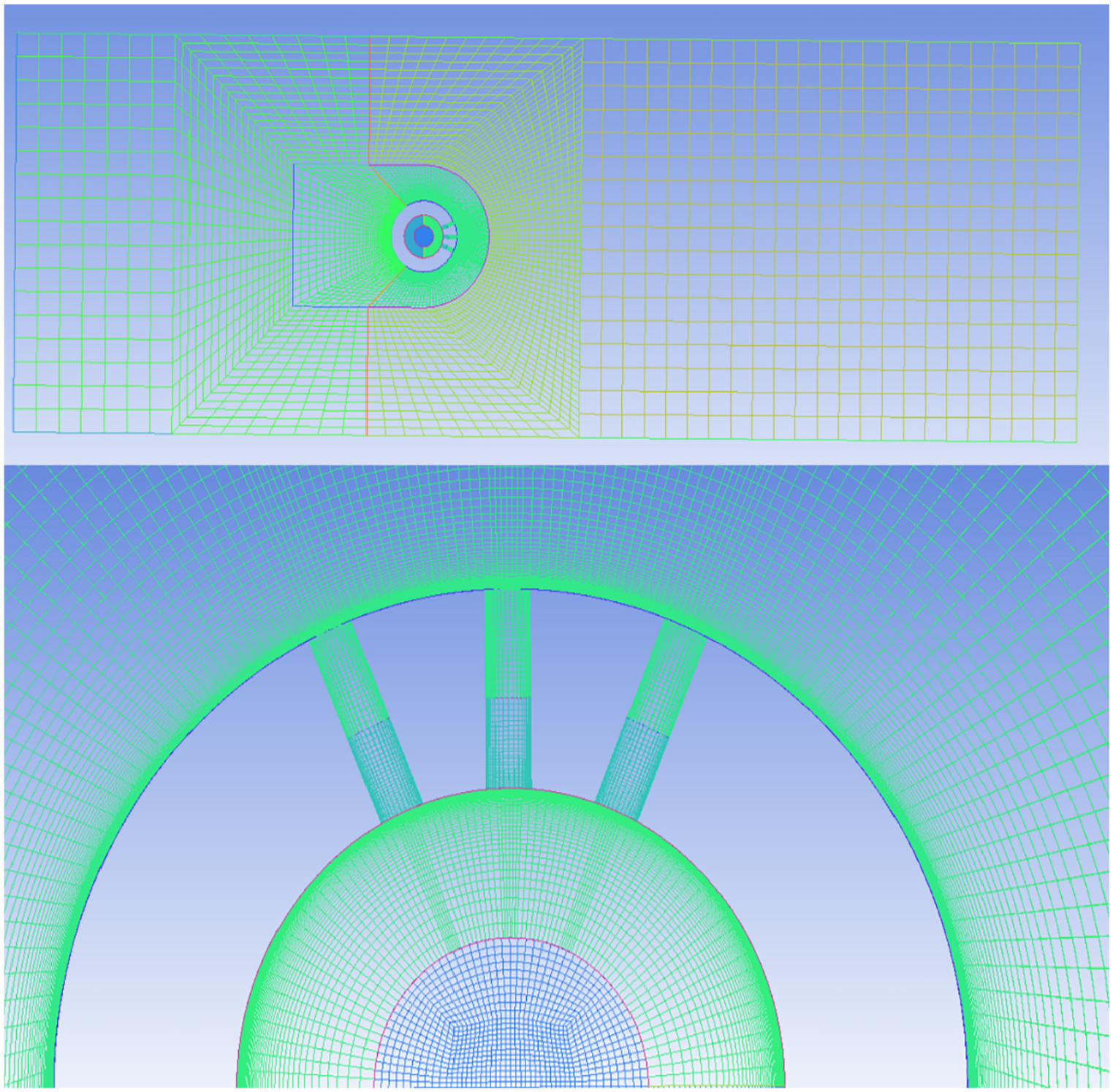
The fluid domain is divided into nine parts to generate 3D structured grids with different densities and the y+ of boundary layer is less than 1 to guarantee accuracy, as shown in Figure 3. The boundary layers from the outer surface of the coolant cavity through the fill hole wall to the blade surface are intersecting. And, this method of respectively generating block grids makes it convenient to replace the mesh of leading edge portion when changing the film hole parameters.

The three-dimensional structured grids.
Shear stress transport (SST) k-ω model and second-order upwind scheme are employed in this study. Semi-implicit method for pressure linked equations (SIMPLE) algorithm is used to couple the pressure and the velocity. The velocity of mainstream at the blade inlet
Working conditions of the simulation.

The blow ratio (M) is an important parameter to describe the film cooling process, which is defined as follows

where
Considering that there are 93 to 183 film cooling holes distributed at different positions on the leading edge of the blade with different local blow ratios, effective blow ratio (M′) is defined as the average blow ratio in this article to describe the relative magnitude of momentum between the jet flow and the main flow. Assume that the flow injected from the inlet of coolant cavity is finally distributed evenly and ejected from each film hole, the effective blow ratio is defined as follows

where N is the total of film cooling holes and A is the cross-sectional area of each hole
The grid sensitivity study was examined with the model of d = 0.5 mm and p = 2.0 mm under a non-rotating condition with the jet mass flow of

Grid resolution study using average temperature of leading edge surface.
The numerical model studied in this article has no experimental results for comparison, but the calculation method has been verified according to experiments of YJ Kim and S-M Kim, 15 and Ou and Rivir. 14 Details can be found in the next section.
Comparisons with available experimental data
A simple simulation on a cylindrical film cooling structure is conducted to verify the feasibility of the calculation method in this article according to the experiment by YJ Kim and S-M Kim,
15
and Ou and Rivir.
14
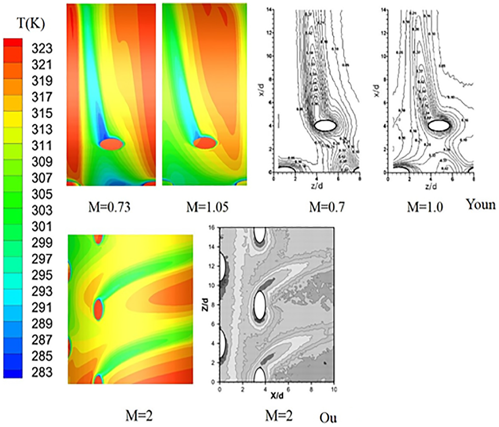
The experimental system and the distribution and structural parameters of the film pores are shown in Figure 5. The cylindrical barrel outer diameter is D1 = 80 mm, inner diameter is D2 = 48 mm, gas film hole diameter is d = 4 mm, spacing is 30 mm (p = 7.5d), and gas film hole length is 32 mm (L = 8d). The composite angle of each row is

Youn et al.’s experimental system: schematic and structural parameters. 15
The experimental conditions are as follows: the flow turbulence is Tu = 0.2%, the flow velocity is Vg = 14 m/s, the mainstream Reynolds number is Re = 7.1 × 10⁴ (based on the cylinder outer diameter), the mainstream temperature is Tg = 303 K, and the jet temperature is Tc = 283 K. The density ratio is about 1 and the working medium is air. The method of measuring the temperature distribution in the experiment is infrared thermal imaging method. The cylinder material is polyacetal resin, and its thermal conductivity is 0.15 W/(m K), so it is considered that the adiabatic temperature and adiabatic cooling efficiency are measured. Structured mesh was generated as shown in Figure 6.
Structured mesh of Youn et al.’s model.
Four different turbulence models are calculated: k-ε model, re-normalization group (RNG) k-ε model, k-ω model, and SST k-ω model. Figure 7 shows the cooling efficiency distribution with different turbulence models and the experimental results. This is due to isotropic turbulence assumptions in the turbulent models in computational fluid dynamics (CFD), resulting in the turbulence models exaggerating the coolant diffusion downstream but underestimating the lateral diffusion.
26
However, the tendency of the CFD results is same as the experimental results, and the temperature distribution with SST k-ω model has good symmetry as shown in Figure 8, and the SST k-ω model can qualitatively demonstrate the phenomenon that occurs in the experiments.
27
Therefore, SST

The cooling efficiency distribution with different turbulence models comparing with experimental data.

The temperature distribution with different turbulence models.
Figures 9 and 10, respectively, show the temperature distribution and the spanwise average cooling efficiency compared with the experimental data at different blow ratios. It can be seen that the computing method can accurately capture the film trail, and the cooling efficiency is in the same order of magnitude as the experimental data. Incomplete thermal insulation and processing roughness of experimental materials result in relatively low cooling efficiency and raise in cooling efficiency in the film hole upstream. Apart from that, the overall trend is the same, so the calculation method is relatively accurate and has reference value.

The cooing efficiency distribution comparing with experimental data.
Results and discussion
Effect of hole diameter
Figures 11–13 show the temperature distribution at leading edge with the change of effective blow ratio and different hole diameters. The spacing between holes in each row is fixed at 2 mm and the effective blow ratio varies from 0.075 to 2.0. Models with hole diameter of 0.3, 0.4, and 0.5 mm are studied. The total pressure of mainstream at the pressure side is greater than that at the suction side for different wall curvature, so it is easier to eject from the third row of film cooling holes (on the suction surface) at the same effective blow ratio. And, backflow is most likely to happen at the second row of holes on the stagnation line of leading edge, which means that the mainstream trespasses into the holes and prevents the coolant from discharging. The backflow also leads to the cooling airflow being heated and the blade temperature increases. With the increase in the effective blow ratio, the film can be off the blade surface, so there can be a value to allow coolant eject from all three rows of holes and this specific blow ratio varies with the change of hole diameter. When d = 0.3 mm, the corresponding blow ratio is 0.75. And, hole diameters 0.4 and 0.5 mm correspond to blow ratios 1.25 and 1.5, respectively. Comparing these three full outflow conditions in Figure 14, it is also clear that the film holes with diameter of 0.3 mm show better coverage. In other words, film cooling holes with smaller diameter require less coolant to achieve the desired cooling effect.

The temperature distribution on the leading edge with the change of M′ (d = 0.3 mm).

The temperature distribution on the leading edge with the change of M′ (d = 0.4 mm).
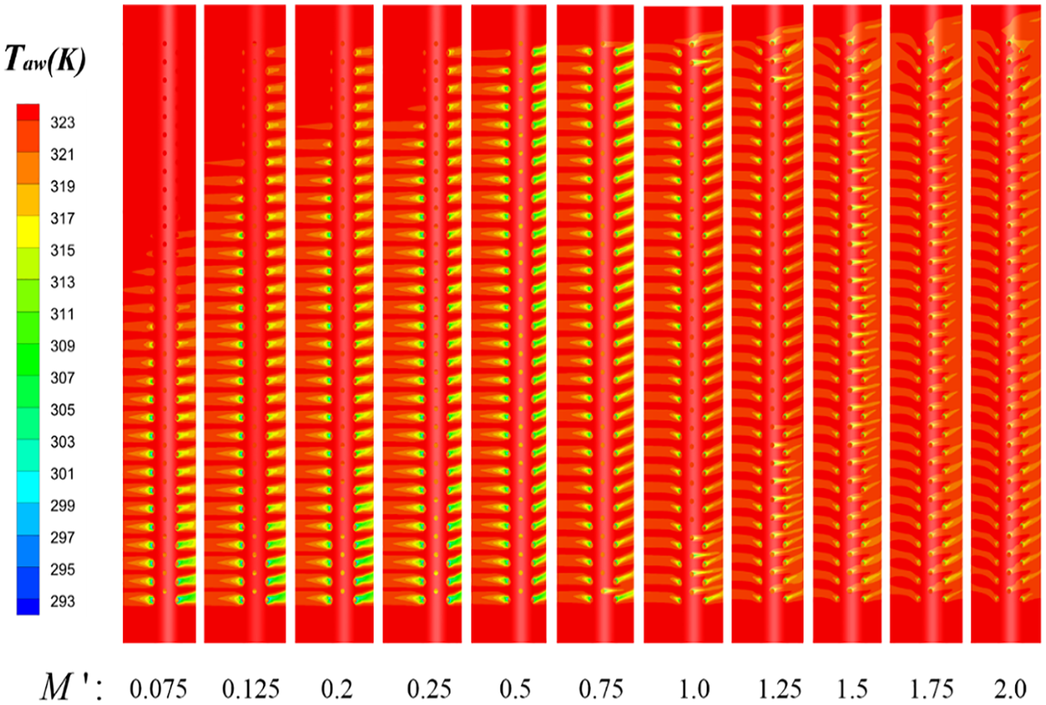
The temperature distribution on the leading edge with the change of M′ (d = 0.5 mm).

The film coverage situation when coolant ejects from all three rows of holes.
Another obvious phenomenon is that though the simulations are conducted under static conditions, the trail of the film in the stationary state gradually inclines upward as the effective blow ratio increases, due to the shear force of the mainstream and the inertial force of the jet.
The ratio of the total pressure in the coolant cavity to that at the outer surface of leading edge determines whether the coolant can eject and form the film. Only stationary states are studied in this article, so the total pressure at the outer surface of leading edge is a constant. And, the total pressure in the coolant cavity is related to the inlet flow. As shown in Figure 15, the average total pressure in the cavity increases rapidly with the increase in effective blow ratio, and smaller hole diameter allows greater growth. Figure 16 shows the total pressure distribution in coolant cavity along the Z-direction with different effective blow ratios. It can be seen that when cold air is insufficient (M′ = 0.25), obvious total pressure saltation happens in the model with 0.5-mm-diameter holes. Decreasing the hole size will relieve the degree of pressure saltation and delay its occurrence.

The average total pressure in the cavity with different d.
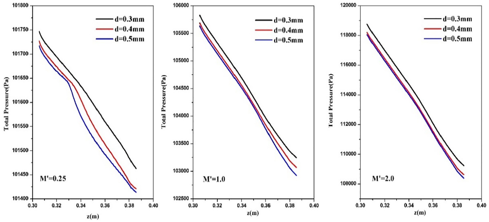
The total pressure distribution along the Z-direction with different d.
The fluid domain near the blade leading edge is divided into 60 areas along stream direction to describe local cooling efficiency. Define the zero point at the leading edge stagnation point, and the distance from the zero point surface is the coordinate s (coordinate along the direction of the suction surface is positive value), as shown in Figure 17. Figure 18 shows the cooling efficiency

where

The division in leading edge region to calculate local cooling efficiency.
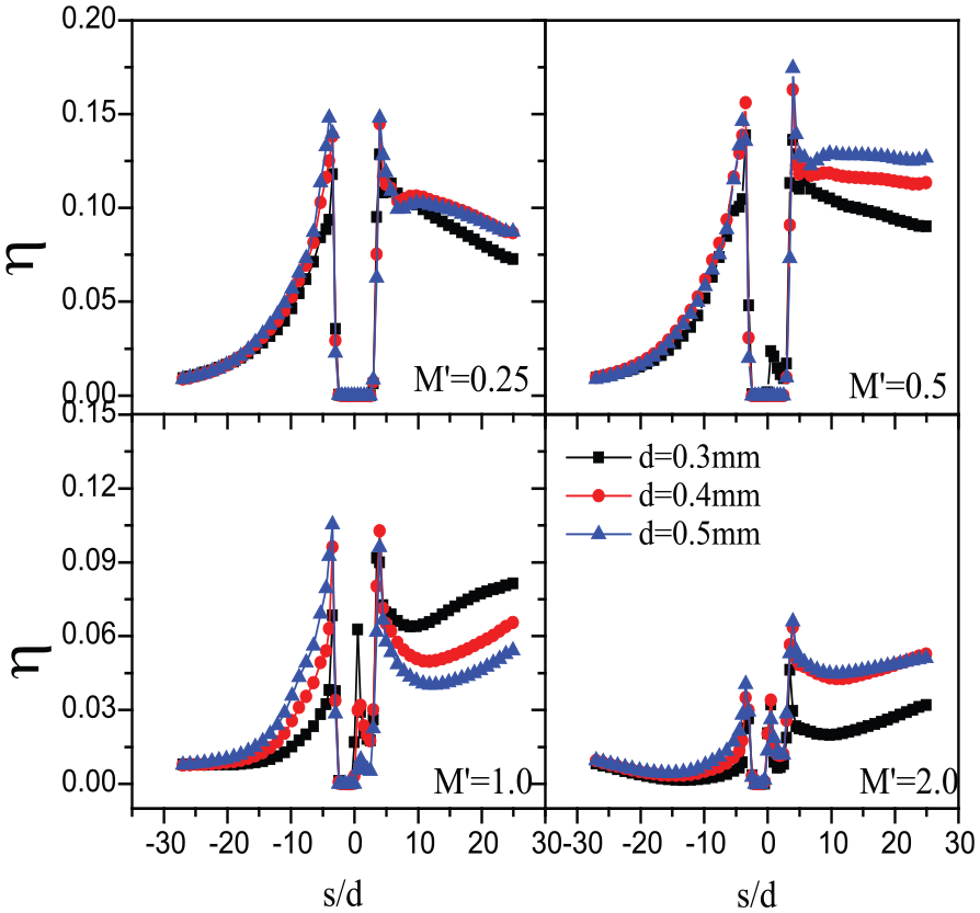
The cooling efficiency distribution with different d.
On the pressure side, the cooling efficiency distribution is less affected by the aperture with low effective blow ratios; when the effective blow ratios is higher, the cooling efficiency is positively correlated with the aperture. The effect of aperture on the cooling efficiency of the suction surface is greater. When the effective blow ratio is low, the jet flow is hard to adhere to the blade surface and form continuous film on model with small diameter holes, so the cooling efficiency declines quickly with coordinates. When the effective blow ratio equals 1.0, model with 0.3-mm-diameter holes performs best, which is because—on this condition—the coolant ejected from the second row of holes forms continuous film and the trail joins into the third row of film. This phenomenon is obvious in Figure 19, which is cut from the middle of the blade suction side. While lager hole diameter means greater cooling film coverage, so when the effective blow ratio comes to 2.0, the cooling efficiency of model with 0.3 mm diameter holes is lowest for the smallest film coverage area. Large effective blow ratio also means larger jet velocity, which makes it harder for coolant to be attached to the wall and so the cooling efficiency is generally lower than other blow ratio conditions.

The film trail on the middle of suction surface with different d.
Effect of hole spacing
Figures 20 and 21 show the temperature distribution at leading edge varying with the effective blow ratio and hole spacing. The diameter of film cooling hole is fixed at 0.3 mm and the effective blow ratio varies from 0.075 to 2.0. Models with hole spacing of 1.0, 1.5, and 2.0 mm are studied. It can be seen that the pressure side and suction side are easy to allow coolant to discharge and form film. When p = 2.0 mm, the effective blow ratio of 1.5 can allow the coolant to eject from each hole. When the hole spacing reduces to 1.5, this specific effective blow ratio increases to 2.0. And, the coolant always cannot eject from each hole on the leading edge within studied blow ratio range when p = 1.0 mm. That is, blade denser film cooling holes requires greater cold flow to achieve full outflow.

The temperature distribution on the leading edge with the change of M′ (p = 1.0 mm).

The temperature distribution on the leading edge with the change of M′ (p = 1.5 mm).
In order to further observe the effect of the distance between the film holes on cooling on the pressure surface and the suction surface, the area in the center of the blade in the Z-direction (height 6 mm) was cut out, as shown in Figures 22 and 23. With the same effective blow ratio, the film trails are longer and can form continuous low temperature area to protect the blade when the cooling holes are denser. This is because smaller hole spacing increases the number of film holes and reduces the outflow from each hole, which helps the coolant to be attached to the blade surface.

The film trail on the middle of pressure surface with different p.

The film trail on the middle of suction surface with different p.
However, dense film cooling holes can lead to more pressure loss and rapid pressure drop in coolant cavity. Figures 24 and 25, respectively, show the average total pressure change with blow ratio and pressure change along the Z-direction. It can be seen that the smaller the distance between the film holes, the more likely the air pressure in the chamber abruptly changes. Therefore, it is difficult for cold air to flow out from the film holes located at the leading edge and in the high radius area of the blade and be attached to the blade surface.

The average total pressure in the cavity with different p.

The total pressure distribution along the Z-direction with different p.
Hole spacing significantly affects the distribution of cooling efficiency, as shown in Figure 26. For the pressure surface, better film adhesion due to smaller hole spacing contributes to higher cooling efficiency, which is especially obvious near the film hole with low effective blow ratio. With high blow ratio, dense film holes’ structure significantly improves the cooling efficiency of the downstream area for forming continuous low temperature area. For the suction surface, the cooling efficiency curves are similar when p = 1.5 mm and p = 2.0 mm. Structure with hole spacing of 1 mm remarkably improves the cooling efficiency with high effective blow ratio, and cooling efficiency of the downstream is even higher than that at the outlet of the film holes.

The cooling efficiency distribution with different p.
Conclusion
The film cooling at the turbine blade leading edge is studied under static conditions considering different film hole diameters and hole spacings. A wide blow ratio range is investigated. By comparing the temperature distribution and cooling efficiency of the blade surface and the jet situation, some conclusions can be summarized as follows:
The backflow phenomenon at leading edge of turbine blade can be controlled and improved by changing the aerodynamic parameters and the geometry and arrangement of film cooling holes. The ratio of the film hole spacing to the hole diameter (p/d) has obvious influence on backflow at leading edge.
The film from each hole becomes more obvious at first with the increase in the effective blow ratio and then fades gradually for departing from the blade surface. Backflow is most likely to happen on the leading edge and the coolant is easiest to eject on suction side.
The trail of the film in the stationary state gradually inclines upward as the effective blow ratio increases due to the shear force of the mainstream and the inertial force of the jet.
The jet flow is controlled by the ratio of the total pressure of coolant cavity and that of the outer surface of blade leading edge. Smaller film hole diameter and larger hole spacing makes it easier to eject coolant and form continuous film by slowing down the pressure in the cavity. That is, increasing the value of p/d can effectively prevent the occurrence of backflow. While larger p/d also makes the film coverage area smaller.
Footnotes
Appendix 1
Handling Editor: James Baldwin
Declaration of conflicting interests
The author(s) declared no potential conflicts of interest with respect to the research, authorship, and/or publication of this article.
Funding
The author(s) disclosed receipt of the following financial support for the research, authorship, and/or publication of this article: This work was financially supported by the National Natural Science Foundation of China (No. 51822602) and the Fundamental Research Funds for the Central Universities (No. YWF-19-BJ-J-293).