
Abstract
This paper presents a comprehensive analysis of an active pendulum vibration absorber (APVA) that utilizes a rotating inertia actuator (RIA) and takes into account the time delay in the position feedback. Here, the primary system is represented as a base-excited system, which includes a linear spring, damper, and mass. The absorber consists of a pendulum with a rotating inertia actuator attached to one end, a spring-damping system attached to the pendulum mass, and a delayed controller. The active control force is generated by the RIA in the proposed model, thereby preventing stroke saturation, an issue that may result in feedback controller instability. This is because, unlike proof mass actuators, the RIA does not have end-stops that limit its motion. The equations of motion describing the dynamical behavior of the primary system and APVA were derived and simulated in MATLAB Simscape and Simulink. Multi- frequency and harmonic base excitations are utilized as inputs. The simulation results show that the proposed APVA can greatly reduce vibration induced by the excitation of both single and multiple frequencies.
Keywords
Background
In engineering systems, unwanted vibrations are caused by a variety of factors; these vibrations result in mechanical component cracks, reduces its operational time and life, fractured structures, noise issues, and so forth. The amplitude of a system’s vibrations increases significantly when the frequency of the external forcing is approximately equivalent to the system’s natural frequency. There are techniques that can be used to control the unwanted vibration. The most frequent method for reducing vibration is to add the dynamic vibration absorber (DVA) 1 to the structure. A passive,2–4 semi-active,5,6 or active DVA 7 is a vibration absorption control technique. The passive DVA has a straightforward design, is simple to install, and has a cheap production cost. However, it can only effectively dampen the vibration of the main system in a narrow frequency range, and its natural frequency is not adjustable. 8 To overcome this limitation, the concept of nonlinear passive dissipative devices has been proposed.9–11 These devices can control vibrations over a wider frequency range, but they also present several drawbacks, such as uncertainties in performance, potential stability issues, and increased complexity in tuning for optimal performance. The advantages of the semi-active DVA include a wider frequency range for vibration reduction, a low consumption of energy, ease of control, etc. 12 However, it cannot effectively eliminate the vibration problem if the frequency range varies greatly. Given the aforementioned restrictions, researchers have recently begun to pay more attention to the active DVA.
An active DVA typically consists of a proof mass, actuator attached to a structure, a collocated vibration sensor and a controller. The actuator for generating forces provides greater adaptability for incorporating enhanced control to provide cancelation forces. Currently, piezoelectric13–15 and electromagnetic16,17 actuators are the most popular in active DVA. Huang and Hung 18 suggested an active DVA based on a piezoelectric actuator that is capable of decreasing beam structural vibration using speed feedback control. However, piezoelectric actuators are better suited for controlling vibrations with a high frequency and modest amplitude. 19 Hence, due to its favorable force characteristics, simple structure, low cost, and ability to produce more force, electromagnetic actuators have been extensively utilized in active vibration control technique. Chen et al. 20 investigated active DVA using permanent magnet actuators and developed a controller for reducing external excitation forces. Following that, the vibration reduction efficacy of active DVA was evaluated using simulation and experiment. González Díaz et al. 21 proposed an electromagnetic active DVA that utilized velocity feedback control and investigated active vibration control with a rectangular panel as the control target. Burdisso and Heilmann 22 presented an active DVA using dual proof masses based on the permanent magnet operating concept. According to the findings of this study, the active DVA with dual proof mass structure may decrease energy usage in half.
In addition, the controller is a crucial research component of the active DVA. In the realm of active vibration control systems, two primary control strategies are commonly employed: feedback control and feedforward control. Feedback control, as commonly used in vibration mitigation, relies on real-time measurements of the system’s response, such as displacement, velocity, or acceleration, to adjust the control input and mitigate vibrations. By continuously comparing the output with the desired state, feedback control is capable of correcting deviations, making it a robust solution for systems experiencing unpredictable disturbances. 23 Several researchers have explored feedback control strategies: Yoshimura et al. 24 designed an active controller using a fuzzy control algorithm, obtaining superior vibration suppression results. Similarly, Wang et al. 25 developed a feedback control technique based on Fuzzy-PID to control vertical vibration acceleration in automobiles, achieving significant vibration mitigation. Thenozhi and Yu 26 applied PID controllers for active vibration control in building structures, and Khot et al. 27 used the PID feedback control method to control vibrations in a cantilever beam. More recent work includes Mohanty and Dwivedy, 28 who investigated the efficiency of a piezoelectric-based nonlinear absorber with time-delayed feedback, and Sun and Song, 29 who examined time-delayed feedback control in continuous beam structures.
Feedforward control, on the other hand, operates by anticipating external disturbances and adjusting the control signal preemptively before the disturbance affects the system. This approach is particularly effective when external excitations are predictable or measurable, as shown in studies like Bohn et al. 30 Feedforward control can enhance the system’s ability to mitigate vibrations when dealing with known disturbance patterns.
The literature analysis mentioned earlier indicates that the majority of research on active DVA is concentrated on active vibration control using proof mass (inertial) actuators. These actuators consist of a mass suspended from a fixed base by an elastic element that is set oscillating by an internal force. However, there is no study on the use of an APVA with RIA in active vibration control for minimizing primary system vibration. Additionally, the time delay in the feedback between sensor and actuator is typically disregarded. Therefore, this study aimed to create a novel vibration absorber that reduces the vibration of the primary system by integrating a pendulum with a rotating inertia actuator and a time delay feedback system. A significant advantage of RIA compared to proof mass actuator is its ability to avoid stroke saturation. The system’s performance is demonstrated by a numerical example of a single-degree-of-freedom structure, referred to as the primary system, that is equipped with the proposed APVA. The response of the actively controlled structure to harmonic and multi-frequency excitation is then compared to that of the passively controlled structure.
Mathematical modeling of the system
Figure 1 shows a schematic of the single degree of freedom primary system equipped with the APVA. From the figure, it can be seen that the absorber consists of a pendulum rod with an RIA attached at one end, a spring-damping system connected to the pendulum mass, and a delayed controller. In this system, the RIA is a critical component that can apply control torque to the pendulum through the rotation of the mass inertia. The mass inertia is driven by a motor according to the pendulum response in real time. The equation of motion of the system can be derived using Lagrange’s equations as follows:

Rotary inertia actuator-based active pendulum dynamic vibration absorber.
According to Figure 1, the kinetic energy and potential energy are
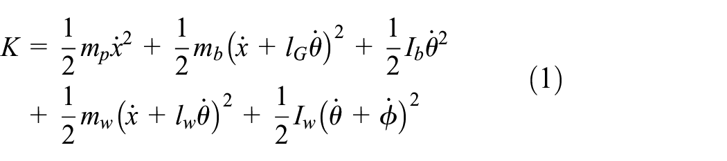
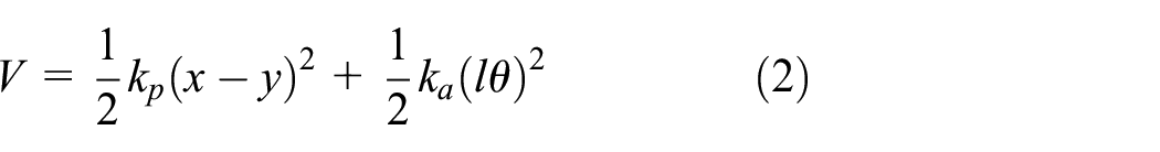
where
System parameters value.

Let

The Lagrange equations for the coordinates

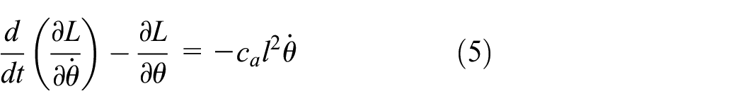

From equations (4)–(6) the dynamic equations can be derived to be

This paper is based on the pendulum displacement feedback as the active control torque of the actuator.

where
Let equation (7)

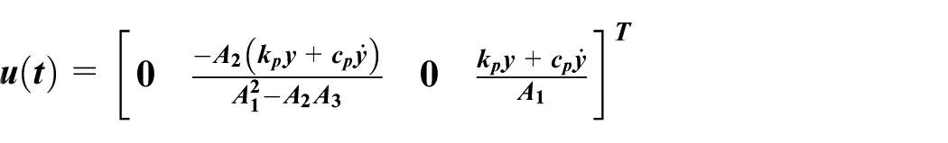
Convert equation (7) into state equation form

where


Passive pendulum vibration absorber tonal tuning
This section will discuss the passive pendulum vibration absorber that is tuned using the tonal tuning technique, which is also known as the Tuned Pendulum Vibration Absorber (TPVA). For tonal tuning, the undamped natural frequency of the absorber is set to the excitation frequency. The undamped natural frequency can be obtained from equation (7) by setting

Then, the undamped natural frequency of the absorber is

Harmonic excitation analysis
Optimum control parameters
To evaluate the performance of the proposed delay position controller in comparison to a classical feedback controller, the concepts of PD control will be discussed at the beginning of this section. If the angular displacement and angular velocity of the pendulum are employed for feedback control, the active control torque of the actuator is expressed as

where
When the harmonic disrupting base excitation is

Substituting these steady-state forms into the system’s equation of motion results in the steady-state displacement amplitude of the primary mass:

in which:

As indicated in the preceding equation, if the proportional and derivative gains are selected as

the steady-state response of the primary mass is zero. The implementation of such a PD control can be costly due to the necessity of both velocity and displacement feedbacks. The following derivation demonstrates that a single time-delayed feedback can achieve the same objective as the PD control.
Since


New variables


where
In order to make the amplitude of primary system

Euler formula is

Using the Euler formula to replace the transcendental term in equation (22) and separating the real part and the imaginary part. The real and imaginary parts are both equal to zero, then calculate the

Since
The optimum time delay can then be calculated as
where
Stability analysis of the combined system
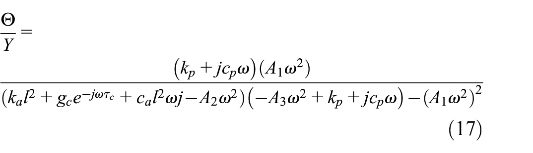
The stability of any feedback control system is of utmost importance. Negative real parts in the roots of the characteristic equation (10) are a sufficient and required criterion for asymptotic stability. However, verifying the root locations is not a simple task. The characteristic equation of equation (10) is given by

where


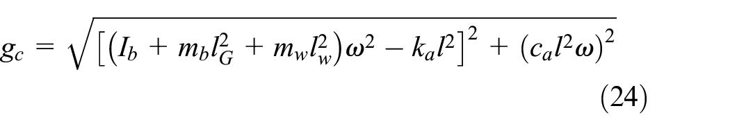
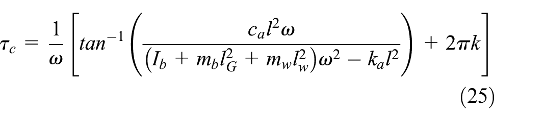
Stability is achieved in the combined system solely when each root of the characteristic equation, referred to as an eigenvalue, possesses a negative real part. When one eigenvalue possesses a positive real part, the system’s vibrations will diverge, ultimately leading to its collapse. Under the essential condition for the occurrence of Hopf bifurcation, the real part of the eigenvalues is set to zero. Consequently, in order to derive the values of the control parameters for the critical condition, it is supposed that the eigenvalues have the form

and

where
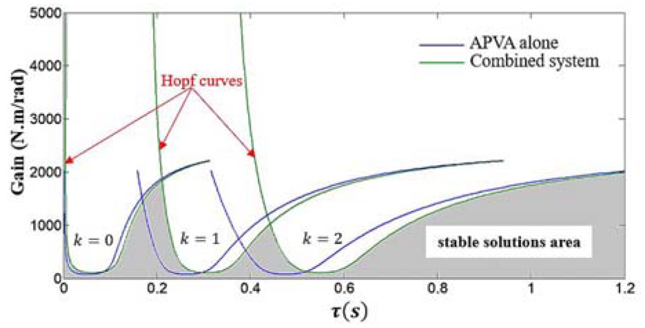
Stability charts for APVA alone and for combined system.
Multi-frequency excitation analysis
Method of precise time integration for dynamic structural equations
The formulation of the multi-frequency base excitation is given as following

where
When the system in Figure 1 is exposed to multi-frequency excitation, the system’s response can be determined using the precise integration method. 31 By considering the time-delay term and the external excitation as nonhomogeneous terms in equation (10), one can express the solution of the equation as

The time step for the numerically discretized equation (30) is

After that, the equation’s solution can be discretized into the stepwise integral formula that follows

Solving the equation yields the system vibration response at each time


Objective function
Assuming that the objective function,


where

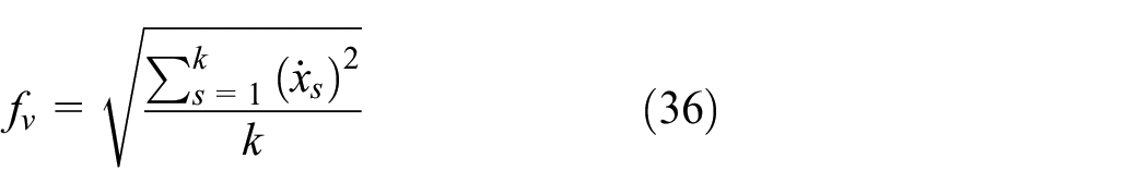

where
Optimization of time-delay control parameters using the particle swarm method
The Particle Swarm Optimization (PSO) approach was initially proposed by Eberhart and Kennedy. 32 It is a stochastic optimization algorithm that operates based on a population of particles. The PSO algorithm finds inspiration in the collective behavior exhibited by fish and birds, and it finds extensive applicability in the field of engineering. A stochastic collection of particles is employed to locate the critical point of the objective function. They proceed by following the nearest particles and utilizing the reproduced velocities to determine the optimal value of the target until the final criterion is met. This research examines the use of constant inertia weight for velocity updating. The execution of PSO involves the following steps.
Step 1 (swarm initialization). In the initial calculation iteration, n pairs of time-delay control parameters (


The numerical solution of the system dynamics equation can be calculated using the time integral method for each pair of time-delay control parameters (
Step 2 (assessment of the objective function). By utilizing the objective function (34), we can compute the value of the objective function f and subsequently store it in an array.

Step 3 (initialization of
Step 4 (update the time-delay control parameters). Once the partial optimal time-delay control parameters for the first group have been obtained, the time-delay control parameters are updated using the subsequent function:

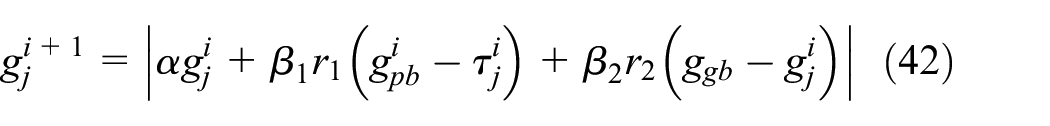
where
The time-delay control parameters of the


Following that, we can obtain the

Step 5 (update the swarm). In the
Step 6 (Ending Criteria). When the specified conditions are fulfilled, the iterations end. If the condition is not met, revert to step 3.
Building physical model using Simscape
The proposed APVA dynamic model in this work is built with Simscape Multibody in MATLAB, which provides a multi-body simulation environment for mechanical systems as well as developing control systems and testing system-level performance without the need for any additional software.
Figure 3 illustrates the blocks used and the connections between different bodies in a multibody model generated with Simscape Multibody. The ground block is utilized to establish the fixed reference world frame, while the machine environment block is responsible for defining gravity. Definitions of inertial properties are necessary for the body block. At various positions, including its center of gravity, it is connected to the ground or other bodies at definitions relative to other points on the body. Assigning degrees of freedom between the bodies is accomplished via a joint block that connects them. The spring damper block represents the spring and damper. In order to apply input force to bodies via the actuator block, three force components must be defined and transmitted into the actuator via the mux block. By means of the body sensor block, the body’s position, velocity, and angular position are detected.
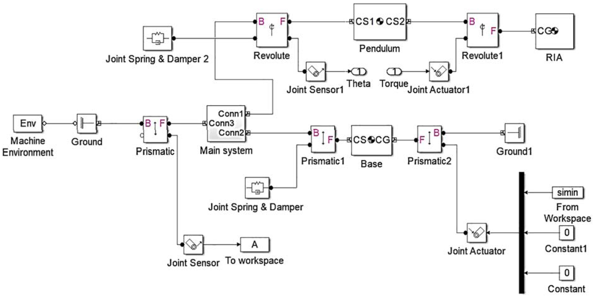
The structure diagram of the Simscape model of the proposed APVA.
Figure 4 illustrates the block diagram of the time-delayed feedback control for the active pendulum vibration absorber system, while Figure 5 presents the PD control block diagram for the same system. Additionally, Figure 6 shows the virtual prototype of the APVA developed using Simscape.

Time-delayed feedback control block diagram of APVA.

PD control block diagram of APVA.

Virtual prototype of the APVA model created by Simscape multi-body.
Dynamic simulations and result
Simulation analysis under harmonic excitation
Consider the external excitation to be

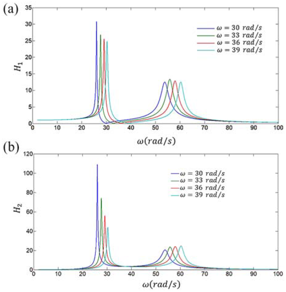
(a) Frequency response function curve of the primary system; (b) Frequency response function curve of the pendulum, with fixed gain and time delay values.
Figure 7 reveals that the frequency domain vibration response of the primary system tends toward zero at


Figure 8 depicts the system frequency response function curve as a result of the action of these four groups of control parameters.
(a) Frequency response function curve of the primary system; (b) Frequency response function curve of the pendulum, with varying gain and time delay parameters.
As illustrated in Figure 8, the time-delay control parameters, derived from equations (24) and (25), can effectively attenuate the vibration of the primary system across a range of external excitation frequencies. The pendulum’s vibration amplitude is large as it enters a resonant state. This highlights the practical capability of tuning the proposed APVA by adjusting the values of
To investigate the effects of time delay on the dynamic response of the primary system, we will adjust the time delay while fixing the control gain

Results of
The advantage of tuning the APVA this way is that it helps reduce energy consumption during control. However, as shown in the figure, an increase in time delay also leads to an increase in vibration amplitude at the anti-resonance point. Therefore, when adjusting the time delay, the level of vibration reduction must be considered. Typically, a vibration reduction of about 80% is used as a standard setting.
Figure 10 illustrates that the displacement magnitude of the primary mass increased as the

Simulation results when

Simulation results for a step-down change in
Based on the information provided in Figures 9–11, with the established actuator gain fixed, increasing or decreasing the time delay
Figure 12 illustrates the dynamic response of the primary system over time under different conditions: with a TPVA, a time-delay vibration absorber, a vibration absorber with PD control, and without an absorber, when excited at its natural frequency. In the case without an absorber, the vertical displacement of the primary system fluctuates between −0.06 and 0.06 m. With a TPVA, the fluctuation range is reduced to −0.048 to 0.048 m. For the vibration absorber with PD control, the vertical displacement is further minimized to −0.00061 to 0.00061 m. However, the time-delay control method used in this research demonstrates that once the vertical displacement stabilizes, the vibration of the primary system is entirely eliminated.
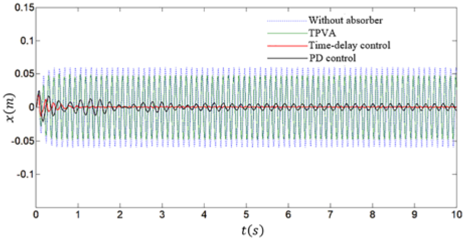
Primary system dynamic displacement.
Simulation analysis under multi-frequency harmonic excitation
In this section, a multi-frequency base excitation in (38) is used to verify the performance of the proposed APVA:

The gain

Displacement response of the primary system.

Velocity response of the primary system.

Acceleration response of the primary system.
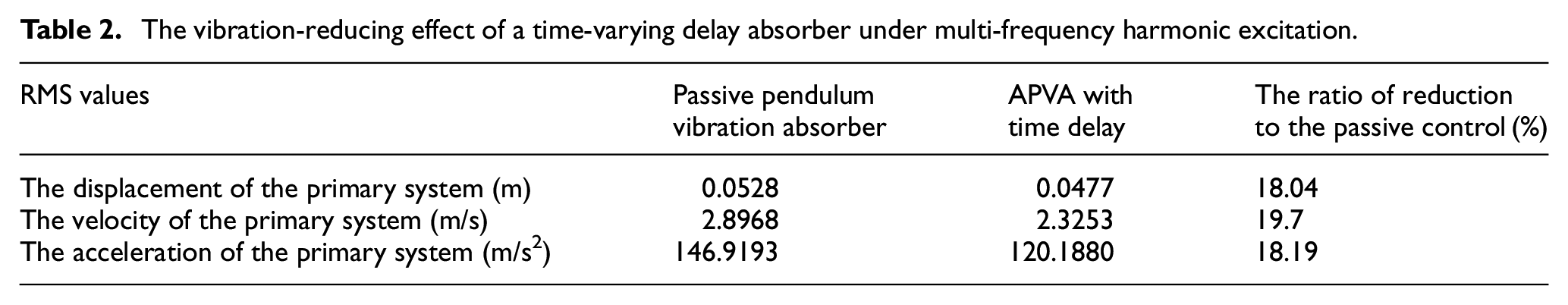
The vibration-reducing effect of a time-varying delay absorber under multi-frequency harmonic excitation.
Conclusions
The design of a novel APVA is presented in this paper. The analysis takes into account time delays in the pendulum’s angular position feedback. This system has a significant advantage over prior active vibration absorbers, particularly in avoiding stroke saturation, which is a common issue in proof mass actuators. The APVA, utilizing a rotating inertia actuator (RIA), mitigates this issue by not relying on end-stop limitations, thus enabling continuous motion without saturation, enhancing system stability and performance under high excitation forces. The mechanism of the proposed device is described by deriving the governing differential equations of motion for the system. To evaluate the performance of the APVA, the proposed device is used to mitigate unwanted structural vibrations caused by harmonic base excitation and multi-frequency base excitation. Numerical simulations were used to estimate the APVA’s efficiency. The simulations were carried out using MATLAB Simscape. The main conclusions of this study are summarized as follows.
(1) Wider Effective Frequency Range: By adjusting the control parameters, particularly the gain and time delay, the effective frequency band for vibration suppression can be broadened. This makes the APVA a more versatile solution, capable of adapting to various operating environments with different excitation frequencies.
(2) Performance Comparison: The APVA outperforms passive vibration absorbers by achieving approximately 18% more vibration reduction in the primary system when subjected to multi-frequency excitations. This highlights the efficacy of active control using the RIA in both reducing vibration amplitude and maintaining system stability.
The results indicate that the proposed APVA is a robust solution for active vibration control, offering superior performance compared to traditional methods, particularly in scenarios where stroke saturation would limit the effectiveness of proof mass-based actuators.
Footnotes
Handling Editor: Carmen Bujoreanu
Declaration of conflicting interests
The author declared no potential conflicts of interest with respect to the research, authorship, and/or publication of this article.
Funding
The author received no financial support for the research, authorship, and/or publication of this article.