
Abstract
The centering mechanism of the nose landing gear is crucial for aircraft operational safety, particularly during the takeoff and landing processes. To address the failure of the return function observed in a certain aircraft, this paper establishes a dynamic model that can effectively characterize the return motion characteristics of the landing gear, considering the synergistic effect of the landing gear buffer device, the shimmy damper, and the centering mechanism comprehensively. On this basis, the four key parameters are studied in depth, including the initial filling pressure of the buffer device, the friction moment of the shimmy damper, the damping coefficient of the shimmy damper, and the contact friction coefficient of the centering mechanism. The results reveal that the return driving moment acting on the piston rod of the nose landing gear increases slowly with the increase in steering angle. At the 90° steering angle, the peak value of the return driving moment is 43.97 Nm. Among the parameters studied, compared with the initial filling pressure and the friction moment of the shimmy damper, the contact friction coefficient of the cam has the most significant effect on the return function.
Introduction
The aircraft landing gear is an important load-bearing component of the aircraft.1,2 It bears static and dynamic loads when the aircraft is in contact with the ground and has an extremely important mission in ensuring the safety of the aircraft.3,4 The centering mechanism applied to the nose landing gear is the key component to ensure the safe take-off and landing process. It is responsible for driving the wheel from any turning position to a neutral position before the aircraft takes off or lands. 5 The centering mechanism is designed inside the landing gear buffer strut. Through a pair of cam devices (an upper cam fixed on the piston rod, and a lower cam fixed on the outer cylinder of the landing gear), the wheel is automatically guided back to the neutral position, and the return driving moment is provided by the compressed gas inside the buffer. 6
During ground taxiing, the buffer device slightly compresses, causing the upper and lower cams to separate, allowing the nose wheel to deflect left or right as needed.7,8 However, the stuck problem of the centering mechanism may lead to serious security risks. Once stuck, it may lead to structural damage or attitude imbalance in the aircraft, thus affecting the landing safety.
Through research, Peng et al. 9 found that friction and wear are the main reasons for the increase in the required minimum pressure angle for the centering mechanism, which affects the return ability of the nose landing gear. By appropriately increasing the pressure angle of the cam, the cam can still maintain its return function after cam wear, thereby improving the safety of the aircraft. Miao et al. 10 conducted a comprehensive analysis of the fault location and underlying mechanisms associated with the slow return issue at small angles in the return process of a tail landing gear. They identified the critical factors that influence the return performance and verified the effectiveness of the proposed solutions through rigorous durability return testing. The research of Tao et al. 11 focused on the friction stuck problem of the external centering mechanism of the helicopter landing gear. They developed a mathematical model for analyzing the friction stuck and solved the critical friction coefficient of the friction stuck. Their research demonstrated that friction stuck will not happen in the centering mechanism with adequate coaxiality. They reduced the risk of friction stuck by optimizing the structure size that affects the critical friction coefficient, which provides a new idea for improving the reliability of the centering mechanism. To return the nose wheel to the centered position after takeoff, Chen 12 proposed a new type of centering mechanism through the analysis and transformation of design requirements and carried out the return performance analysis and experimental verification of the mechanism. In the previous studies, the kinematic model was usually established to discuss the fault causes of the landing gear centering mechanism, but the detailed analysis was not carried out from the perspective of dynamics motion. In addition, there is a lack of quantitative evaluation of the impact of various parameters.
The primary contributions of this study can be summarized as follows:
A novel dynamic response model was developed, specifically characterizing the centering process of the nose landing gear. Unlike existing models that focus solely on kinematics, this model incorporates the interaction of multiple components, including the buffer device, shimmy damper, and centering mechanism, to analyze the full dynamic behavior during the centering motion. This comprehensive approach provides a more detailed representation of the system’s response under various conditions.
A quantitative analysis of key design parameters was performed, focusing on the effects of the initial filling pressure of the buffer, the friction moment and damping coefficient of the shimmy damper, and the contact friction coefficient of the centering mechanism on centering failure. The boundary conditions for parameter combinations leading to centering failure were defined, addressing a gap in previous studies, which lacked detailed parameter analysis.
The remainder of the paper is structured as follows: Section “Return dynamic response model of nose landing gear” first establishes a dynamic simulation analysis model, focusing on the returning dynamics of nose landing gear. Then, Section “Influence of shimmy damper on return function of nose landing gear” investigates the influence of the shimmy damper on the return function. In Section “Analysis of influencing parameters on return dynamic characteristics,” the quantitative impact of four parameters on the return function are analyzed. Finally, conclusions are given in Section “Discussion.”
Return dynamic response model of nose landing gear
The nose landing gear of the studied aircraft and its centering mechanism is depicted in Figure 1. The primary components of the nose landing gear include the outer cylinder, piston rod, torque link, wheel, shimmy damper, and centering mechanism. Notably, the lower cam is affixed to the outer cylinder, while the upper cam is attached to the piston rod. A sealing ring is installed on the outer side of the upper cam to prevent oil leakage during the buffer compression process. 13 The right side of Figure 1 shows the situation of the centering mechanism in its initial state and the −30° steering angle of the nose landing gear.

Schematic diagram of nose landing gear and centering mechanism.
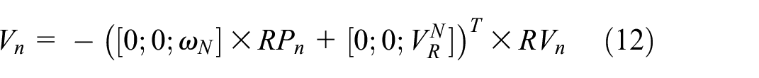
When the aircraft takes off, the motion of the nose landing gear piston rod is mainly affected by the buffer load, the contact load from the centering mechanism, and the anti-swing moment of the shimmy damper. 14 The translational and rotational dynamic equations of the landing gear piston rod can be described by the following equations:

where
Dynamic model of buffer device
The buffer device of landing gear primarily consists of key components such as the buffer cylinder, piston rod, orifice, and sealing rings. Its operation is based on a combination of hydraulic and pneumatic forces: when the aircraft lands, the piston rod enters the buffer cylinder, compressing the gas inside and pushing the hydraulic oil through the orifice. The flow of hydraulic oil generates damping force, thereby absorbing and mitigating the impact energy. The compressed gas provides the elastic restoring force, pushing the piston rod back to its initial position. In the centering process of the nose landing gear, the buffer device provides the returning driving moment through gas pressure, driving the landing gear from the deflected angle back to the neutral position. Additionally, the damping effect of the hydraulic oil helps smooth the centering process, preventing excessive shocks and vibrations.
The axial resultant force

The internal gas of the buffer will be compressed when there is a relative displacement between the piston rod and the outer cylinder. Assuming that the internal gas is in an adiabatic environment and the volume of the buffer gas chamber is constant, the gas spring force can be expressed as:

where
The oil damping force of the buffer is calculated as follows 17 :

where
There is a significant difference in the oil hole area when the movement direction of the buffer piston rod is different. The total area of the oil hole can be calculated using the following equation:

where
The outer cylinder of the buffer and the piston rod will produce axial friction when there is relative motion. After the nose landing gear is off the ground, the friction of the buffer piston rod is mainly generated by the sealing ring. The empirical expression is as follows:

where
Dynamic model of shimmy damper
The shimmy damper provides damping moment and friction moment during the return process of the piston rod. The calculation equation is as follows 18 :

where
Dynamic model of centering mechanism
The actual contact between the upper and lower cams in the centering mechanism is surface-surface contact. 19 Given the complex nature of constructing a mathematical model for surface contact, which hinders further research on the coupling influence of multiple parameters, this section employs the point-line contact method to determine the contact load between the upper and lower cams of the centering mechanism. The corresponding diagram, shown in Figure 2, illustrates that the cam edge is expanded into a straight line.

Equivalent modeling diagram of contact force.
The specific modeling process is as follows:
As the lower cam is fixed to the outer cylinder of the landing gear, when the global coordinate system
The local coordinate system
Considering the unreasonable phenomenon of the contact force model established by the linear spring-damping system, this paper introduces the Gonthier contact force model to calculate the contact force between each contact reference point and the lower cam one by one. 20 The equation is:

where
Considering the accuracy and consuming time of contact load calculation, this paper compares and analyzes the number of reference points. Finally, the number of contact reference points is determined to be 30, and 15 reference points are arranged on the left and right sides of the upper cam. The contact load analysis process of each reference point is basically the same, so this paper only selects one of the reference points to carry out the detailed derivation of the force analysis process, and the reference point is recorded as point
Firstly, the position of point
where
The representation function of the vertical coordinate

where the definition of

Definition of lower cam edge height.
Subsequently, as the upper cam moves with the piston rod, the embedding depth

in which,
By substituting the compression distance and compression velocity of the reference point

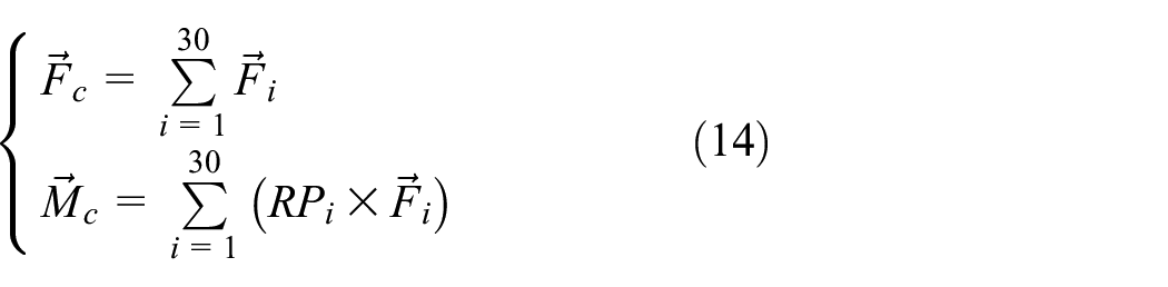
Then, considering the comprehensive influence of each contact point, the force vector
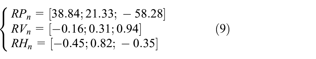
Since only the component of the contact load in the axial direction of the buffer and the moment generated around the axial direction of the buffer are considered when establishing the dynamic model of the centering mechanism, the relevant state can be expressed as follows:

Influence of shimmy damper on return function of nose landing gear
This section will first analyze the effective return driving moment generated by the centering mechanism under different steering angles of the piston rod and then discuss the concrete influences of the shimmy damper on the landing gear return dynamics. The key parameters of the nose landing gear required for subsequent simulation are shown in Table 1.
Key parameters required for return simulation of nose landing gear.

Return driving moment at different steering angles
Based on the above dynamic response model, the return driving moment of the centering mechanism under different steering angles is calculated. The simulation results are shown in Table 2. It can be seen that when the steering angle increases from 0° to 1°, the driving moment generated by the centering mechanism increases rapidly to 37.59 Nm. Since then, the return moment has increased slowly with the increase in the steering angle. When the steering angle increases to 90°, the return driving moment generated by the centering mechanism is 43.97 Nm. According to the mechanism of the return moment, the current moment change is mainly due to the change of the buffer compression distance, which changes the gas spring force. Therefore, when the steering angle is larger, the gas spring force is greater, which increases the contact force between the upper and lower cams.
Return driving moment under different piston rod steering angles.

To ensure the validity of the model, a simple experiment was conducted to measure the return driving moment at various steering angles of the nose landing gear. As shown in Figure 4, the pentagram represents the obtained data. It can be found that the maximum relative difference of the return driving moment between simulation and test data is 4.8%. Therefore, the simulation results have a certain degree of matching with the test results obtained from the test of nose landing gear return function. The dynamic model of the return function can be utilized for the later research.
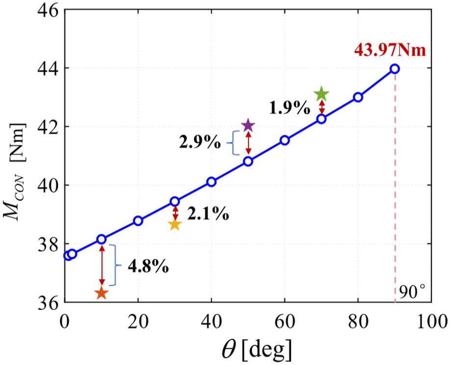
The relative difference of the return driving moment between simulation and test results.
Influence of shimmy damper on return motion of nose landing gear
Figure 5 shows the motion state curves of the piston rod under three different initial steering angles of −30°, −60°, and −90°. The centering mechanism is fixed to the initial steering angle at 0–1 s in the simulation process and begins to move under the action of the return driving moment and the resisting moment generated by shimmy damper after the fixed constraint is removed. Comparing Figure 5(a) with Figure 5(c), it can be found that the return rate of the piston rod decreases greatly under the action of the shimmy damper. When the piston rod is not affected by the shimmy damper, the three types of working conditions only need 1–2 s to complete the return process. At the same time, after the intervention of the shimmy damper, the piston rod cannot be restored to the median state, and finally it is stationary at the position of −3.26° steering angle.

Influence of the shimmy damper on nose landing gear return process: (a) change of steering angle without shimmy damper, (b) change of steering angular velocity without shimmy damper, (c) change of steering angle with shimmy damper, and (d) change of steering angular velocity with shimmy damper.
It can be seen from Figure 5(c) and (d) that, taking the −30° steering angle condition as an example, the peak steering angular velocity of the piston rod without the influence of the shimmy damper is 127.89°/s, which is much larger than the steering angular velocity of 2.69°/s after the shimmy damper is installed. The main reason for this difference is that the shimmy damper provides a large damping moment during the piston rod steering process. 21
Figure 6 shows the return driving moment and hindering moment of the piston rod during the movement under the condition of −90° steering angle. It can be seen that the piston rod is subjected to the effective moment that drives its own steering only during the period from 1 to 1.2 s, causing the steering angular velocity to rise rapidly. Subsequently, the resultant moment is negative, which is unfavorable for its own steering, causing the steering angular velocity to gradually decrease until it approaches 0.
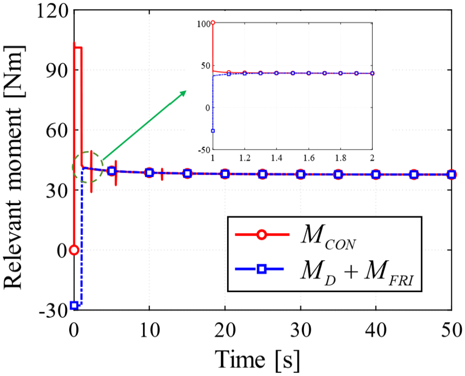
Driving moment and hindering moment of nose landing gear piston rod in return process.
Analysis of influencing parameters on return dynamic characteristics
This section focuses on four parameters: the friction moment of the shimmy damper, the damping coefficient of the shimmy damper, the contact friction coefficient of the cam, and the initial filling pressure of the buffer device. It analyzes the influence of these parameters on the return dynamic characteristics of the landing gear. The fourth condition of each parameter represents the actual value for the current landing gear. The research conditions are set at 70%, 80%, 90%, 100%, and 110% of the actual values, respectively. By conducting numerical simulation studies under various conditions, the specific influence degree of different parameters can be explored, so as to provide guidance for the future comprehensive optimization of landing gear parameters. The research conditions are as shown in Table 3.
Parameters which affect nose landing gear return characteristics.

Influence of friction moment of shimmy damper
Figure 7 illustrates the return motion characteristics of the landing gear under the influence of different friction moments of the shimmy damper. It can be observed from Figure 7(a) that the friction moment of the shimmy damper has a significant impact on the return process of the studied landing gear. For the first three conditions, the nose landing gear is capable of returning the piston rod to the center position, with the required times being 3.59, 4.84, and 8.71 s, respectively. When the friction moment increases to 30.47 Nm, the piston rod will move from steering −60° to −45.21° and stop at the current position. It can be found from Figure 7(b) that when the friction moment of the shimmy damper is only 19.39 Nm, the steering angular velocity of the piston rod increases rapidly to 29.19°/s, which makes the landing gear return in a very short time. Subsequently, a collision occurs between the upper and lower cams at the end of the motion, causing the steering angular velocity to quickly decrease.

The influence of the friction moment of the shimmy damper on the return dynamic characteristics of the nose landing gear: (a) the trend of changes in the piston rod steering angle and (b) the trend of changes in the piston rod steering angular velocity.
Therefore, the numerical selection of the friction moment value for the shimmy damper should take into account two factors: it should ensure the realization of the landing gear’s return function, and it should not be set too low, which could lead to frequent collisions between the upper and lower cams, resulting in wear.
Influence of damping coefficient of shimmy damper
Figure 8 illustrates the return motion characteristics of the nose landing gear under the influence of different damping coefficients of the shimmy damper. For the landing gear studied, the change of damping coefficient has little effect on the movement of piston rod, and there is no difference in the time tending to be stationary and static angle of piston rod. For the damping coefficients of 7 and 11 Nm/(rad/s), the maximum peak values of the steering angle velocity are 7.03 and 6.09°/s, respectively.

The influence of the damping coefficient of the shimmy damper on the return dynamic characteristics of the nose landing gear: (a) the trend of changes in the piston rod steering angle and (b) the trend of changes in the piston rod steering angular velocity.
Influence of contact friction coefficient of cam
Figure 9 demonstrates the variation of the landing gear’s return motion characteristics with different contact friction coefficients of the upper and lower cams in the centering mechanism.

The influence of the contact friction coefficient of the cam on the return dynamic characteristics of the nose landing gear: (a) the trend of changes in the piston rod steering angle and (b) the trend of changes in the piston rod steering angular velocity.
The contact friction coefficient significantly influences the return process of the studied landing gear. For the first three conditions, the nose landing gear is able to achieve the whole return process of the piston rod, with the required times being 2.49, 3.32, and 5.71 s, respectively. When the friction coefficient of the contact surface increases to 0.22, the piston rod will move from a steering of −60° to −56.64° and then stop at the current position. Changes in the cam contact friction coefficient will lead to a decrease in the return driving moment of the piston rod generated after the upper and lower cams come into contact, which results in it being insufficient to overcome the friction resistance moment produced by the landing gear buffer and the shimmy damper.
Influence of initial filling pressure of buffer device
Figure 10 illustrates the landing gear’s return motion characteristics under different initial filling pressures of the buffer device.

The influence of the initial filling pressure of the buffer device on the return dynamic characteristics of the nose landing gear: (a) the trend of changes in the piston rod steering angle and (b) the trend of changes in the piston rod steering angular velocity.
From the figure, it can be observed that when the initial filling pressure of the buffer device is only 70%, 80%, and 90% of the actual value, the driving moment produced by the centering mechanism is not sufficient to drive the nose landing gear to perform the return motion. When the filling pressure of the buffer device is increased to 110% of the actual value, the landing gear piston rod can be restored to its initial position at 6.43 s.
Quantitative evaluation of parameter influence degree
The core of the landing gear centering mechanism relies on the return driving moment acting on the piston rod being greater than the combined resistance moment it encounters during its motion. According to the data results in Table 2, it is evident that the return driving moment generated by the mechanism gradually decreases as the steering angle reduces. Therefore, this paper quantitatively evaluates the influence degree of three parameters on the return motion characteristics of the studied landing gear through the moment difference in the state of −1°, containing shimmy damper friction moment
When the moment difference under the −1° state is larger, the reliability of the return function is higher. The equation is expressed as follows:

Figure 11 illustrates the influence patterns of the shimmy damper friction moment

The coupling influence law of two parameters on the landing gear return process.
At the same time, combined with the simulation results, the failure boundary of the nose landing gear return function has been drawn in Figure 11. Maintaining the initial filling pressure of the buffer unchanged, it should be ensured that the parameter combination of
Figure 12 demonstrates the coupled influence of three parameters on the return performance. The five surfaces from bottom to top correspond to the buffer device’s initial filling pressures of 0.90, 1.20, 1.5, 1.80, and 2.10 MPa, respectively. It can be observed from the figure that the initial filling pressure of the buffer device

The coupling influence law of three parameters on the landing gear return process.
Based on the simulation analysis results, it is clear that the contact friction coefficient between the upper and lower cams plays a crucial role in the performance of the centering mechanism, and thus should be closely monitored during use and maintenance.
Actual inspections of the studied nose landing gear have indicated that the primary cause of the failure of return function, is due to wear on the contact surfaces of the upper and lower cams, which leads to an increase in the friction coefficient compared to the initial design value.
Discussion
This section discusses the trends and key findings from the return dynamics analysis of the nose landing gear, focusing on the influence of critical parameters, as depicted in Figures 4 to 12.
As shown in Figure 4, the return driving moment increases nonlinearly as the steering angle increases from 0° to 90°, reaching a peak value of 43.97 Nm. This trend can be attributed to the increased compression of the buffer, which generates greater spring force from the compressed gas. The simulation results closely match the experimental data, with a maximum relative error of only 4.8%, confirming the validity of the model in predicting the return motion.
Figure 5 explored the effect of the shimmy damper on the return motion of the nose landing gear. The inclusion of the shimmy damper significantly reduced the return speed, causing the system to stop at a steering angle of −3.26° across three different conditions. In contrast, without the damper, the nose landing gear returned to the neutral position within 1–2 s. This behavior highlights the critical role of the shimmy damper in dissipating kinetic energy, effectively slowing the return motion.
As illustrated in Figure 7, the results show that an increased friction moment significantly delays the return motion. For instance, with a friction moment of 30.47 Nm, the piston rod stopped at a steering angle of −45.21°. In contrast, with a smaller friction moment of 19.39 Nm, the return was completed more rapidly, and the maximum angular velocity reached 29.19°/s. These results underline the critical role that the friction moment of the shimmy damper plays in the return process, suggesting that controlling the friction moment is essential for optimizing the performance of the centering mechanism. In Section “Influence of damping coefficient of shimmy damper,” Figure 8 shows that variations in the damping coefficient of the shimmy damper have minimal impact on the return motion of the nose landing gear. Both the return time and final stopping angle showed little change across different damping coefficients, suggesting that the damping coefficient plays a limited role. The impact of the contact friction coefficient between the upper and lower cams was examined, with results shown in Figure 9. As the friction coefficient increased to 0.22, the piston rod failed to return completely, stopping at a steering angle of −56.64°. This happens because the increased friction torque surpasses the return driving moment, thus preventing full return motion. This result confirms that the friction coefficient is a critical factor in the design of the centering mechanism, as excessive friction can lead to incomplete return motion. The findings agree with existing studies, which also highlight the detrimental effects of high friction on mechanical systems. 9
At last, a quantitative evaluation of the influence of key parameters was conducted. Figure 11 shows that the contact friction coefficient of the cam had the most significant impact on the return function, while the friction moment of the shimmy damper had a lesser effect. When the contact friction coefficient was reduced, the return driving moment increased substantially. This observation underscores the importance of controlling the friction coefficient in both design and maintenance to ensure optimal performance and prevent failure due to wear.
Conclusions
This paper conducts a detailed analysis of the return function of a certain nose landing gear, establishing a dynamic simulation model that effectively characterizes the return process. The study evaluates the influence of various parameters on the return dynamics through multi-condition simulations, leading to the following key conclusions:
Considering the impact of the landing gear buffer and the shimmy damper, a mathematical model for the return motion of the piston rod is developed based on a simplified contact force model, and the return driving moment produced by the upper-lower cam mechanism at different steering angles is derived. The simulation results show a reasonable match with the data collected during the return driving moment test of the nose landing gear, confirming the validity of model for investigating the causes of return function failures;
The presence of the shimmy damper plays a critical role in the effectiveness of the return function. For the studied nose landing gear, without the shimmy damper, it can quickly return to the center within 2 s. However, the intervention of the shimmy damper will cause it to stop at a steering angle of −3.26°;
An influence study is conducted on three parameters: the friction moment of the shimmy damper
Footnotes
Handling Editor: Aarthy Esakkiappan
Author contributions
Conceptualization, Y.Z.; methodology, S.Z.; formal analysis, S.Z.; writing-original draft preparation, S.Z.; writing-review and editing, S.Z.; visualization, Y.Z.; supervision, Y.Z.; project administration, Y.Z. All authors have read and agreed to the published version of the manuscript.
Declaration of conflicting interests
The author(s) declared no potential conflicts of interest with respect to the research, authorship, and/or publication of this article.
Funding
The author(s) received no financial support for the research, authorship, and/or publication of this article.
Data availability
Data are contained within the article.