
Abstract
As a typical precision machine, the machine tool has complex structure and changeable working conditions, which leads to huge calculation data and low analysis efficiency when using traditional finite element method to obtain stiffness information. General test methods often have discrete values and cannot obtain stiffness information comprehensively and systematically. In this paper, a method for characterizing the stiffness of machine tool processing space based on multi-body system topology is proposed. Based on the matrix condensation theory, a method for constructing the equivalent condensation model of the stiffness of machine tool components is proposed. The stiffness characterization model of the components is established by using the stiffness equivalent condensation method. Based on the multi-body system theory, the stiffness distribution model of machine tool machining space is established, which can quickly and intuitively characterize the machining stiffness information of machine tool. Finally, based on the stiffness distribution model of the machining space of the machine tool, the machining accuracy of the S-shaped test specimen is predicted. Combined with the experimental analysis, the measurement results are consistent with the prediction results. The accuracy, feasibility, and effectiveness of the stiffness distribution model of machine tool machining space are verified.
Keywords
Introduction
Machine tool stiffness is an important factor affecting the machining accuracy of a machine tool. Machine tool stiffness is affected by its topological layout, structural configuration, and other internal design factors, which are costly to adjust in the design and manufacturing process of machine tools and difficult to fully characterize.1,2 In recent years, domestic and foreign experts and scholars on the stiffness information acquisition methods and stiffness characterization methods can be divided into stiffness numerical analysis methods and stiffness test methods.3–5 The stiffness numerical analysis method uses the finite element to establish the digital model of the research object, and obtains the stiffness information through the numerical simulation and analysis of the model. The scholar Ying Jun et al. used the motorized spindle bearing of the CNC machine tool as the research object. Aiming at the problem that it is difficult to express the dynamic load of the motorized spindle, the bearing deformation and the bearing performance, and the bearing life, the nonlinear dynamic model of the motorized spindle bearing is established. Considering the influence of bearing defect shape, bearing deformation, and other factors on the performance degradation of the motorized spindle bearing, the stiffness deformation, performance degradation state, and theoretical life of the motorized spindle bearing are predicted under variable load conditions.6–8 In order to effectively identify the weak parts of the cantilever structure in the tail frame and bed of the machine tool, Guo et al. used the finite element method to numerically simulate the cantilever structure of the machine tool, and established the stiffness reduction model of the cantilever structure. At the same time, the sensor was used to collect the stiffness deformation data of the cantilever structure of the machine tool. The results show that the finite element simulation results are in good agreement with the experimental structure, and the weak areas of the cantilever structure in the tail frame and bed are obtained.9,10 The above stiffness numerical analysis method can not adapt to the complex and changeable working conditions in practical engineering, and the application range is greatly limited. The test and experimental methods of stiffness characterization are mainly to obtain stiffness information by direct measurement of the research object. Many scholars have designed many measurement methods to obtain stiffness information of different measurement objects. For different measurement objects, many scholars have designed many measurement methods11–16; some scholars have introduced the shrinkage theory to simplify the stiffness information, and established a normalized stiffness characterization model for machine tool components,17,18 which effectively reduces the amount of calculation. At the same time, the machine tool as a typical multi-body system, when the constituent parts of the machine tool is loaded, the deformation generated by itself and the external load will be transmitted along the tandem kinematic chain of the machine tool, and ultimately superimposed on the end of the machine tool actuator.19,20 In terms of machine tool machining accuracy inspection and prediction, related scholars21,22 designed relevant experiments to collect data such as contour error and surface quality of machine tool machining, so as to evaluate the advantages and disadvantages of machine tool machining accuracy.
In order to study the influence of the structural design of the machine tool on the accuracy of the machine tool, Cheng et al. 23 used the multi-axis machine tool as the research object, and used the multi-body system theory to establish the volume error model of the machine tool. Based on this model, combined with the random process theory, the equivalent error of the machine tool processing space and the fluctuation of the processing accuracy were predicted. Scholars Okafor and Ertekin 24 used the vertical machining center as the research object, used the rigid body kinematics theory to perform homogeneous coordinate transformation, and modeled the attitude error of the machining center. The model can predict the linear positioning accuracy of the machining center under multiple attitudes including roll and pitch.
In order to study the influence of cutting load on the accuracy of the machine tool during the machining process, Fan et al. 25 proposed a mathematical model. The model can calculate the reaction force transmitted to the guide rail-slider of the machine tool according to the cutting load. According to the static equilibrium equation of the slip body deformation-free body, the contact deformation caused by the wear of the guide rail and the geometric error of the slider are solved, and then the position error of the machine tool after long-term operation can be predicted. Archenti and Nicolescu 21 established the reaction-deformation deviation calculation model of each joint in the machine tool space by arranging sensors to measure the load at the tool holder and workbench during the milling process. Through this model, the machining error caused by the joint stiffness and joint deformation of the machine tool can be solved during the whole machining process.
In order to study the influence of process parameters on the accuracy of machine tools during machining, scholars Chiu and Lee 22 used CNC machine tools as the research object. Firstly, relevant experiments were designed to collect data such as contour error and surface quality of machine tools. Based on fuzzy rules, a prediction model for these two indicators was established. Through this model, the contour and surface quality of machining can be predicted based on CNC machining parameters, so as to evaluate the machining accuracy of machine tools. Scholars Xie et al.26,27 focused on the influence of feed speed on the position accuracy of machine tools, established a position accuracy prediction model through a large number of previous experimental data, and proposed a position accuracy control method combining real-time dynamic feedforward and feed speed adjustment. According to the position accuracy results obtained from real-time prediction, the adjustment of feed speed can be dynamically controlled, thereby limiting the machining error caused by the input signal.
Based on the above research status of machine tool machining accuracy analysis methods, it can be found that the machining accuracy of machine tools is affected by multiple factors such as its own structural design, cutting load, and processing parameters. At this stage, the prediction method of machine tool machining accuracy often only considers one of the factors, which is not consistent with the actual working conditions. Therefore, this paper proposes a universal method that can accurately predict the machining accuracy error of the machine tool based on the internal cause of the spatial stiffness of the machine tool and the external cause of the process system.
Based on the current research status of spatial stiffness characterization of machine tools, there are still problems such as incomplete characterization of machine tool stiffness, inability to normalize characterization, and difficulty in predicting machining accuracy. In this paper, a method for characterizing the stiffness of machine tool processing space based on multi-body system topology is proposed. Based on the matrix condensation theory, it is deduced that the stiffness characteristics of the component system can be characterized by the key geometric feature set that only bears the external load when the stiffness is equivalently condensed. The stiffness characterization model of machine tool components such as multi-constraint components and multi-position components is established by using the stiffness equivalent condensation method. Based on the multi-body system theory, the machine tool system is described as two series motion chains and the deformation transfer relationship is analyzed. The stiffness distribution model of the machine tool machining space is established, which can quickly and intuitively characterize the machining stiffness information of the machine tool. Finally, based on the stiffness distribution model of the machining space of the machine tool, the machining accuracy of the S-shaped test specimen is predicted. Combined with the experimental analysis, the measurement results are consistent with the prediction results. The accuracy, feasibility, and effectiveness of the stiffness distribution model of machine tool machining space are verified.
The spatial stiffness distribution of machine tools based on the theory of multibody systems
Topology configuration of machine tool multibody systems
A certain model of high-precision CNC (CNC machining center) machining center in the working state, can be abstractly viewed as a multi-body system consisting of five components: bed, column, table, spindle box, slide saddle.
In the multibody system of the machine tool, the inertial reference frame R is selected and labeled as D0, the bed structure is labeled as D1, and then the other constituent structures are numbered based on the direction away from the bed. Subsequently, the low-order body array method is applied to describe the topological structure of the machine tool multibody system, as shown in Figure 1:

Structure and topology of machine tool multibody system.
The elements that constitute the topological structure of multi-body systems are called typical bodies of multi-body systems. In Figure 1, 1 is the bed, 2 is the column, 3 is the sliding saddle, 4 is the main axle box, 5 is the workbench, and 6 is the workpiece to be processed. Any component of the machine tool is a typical body in the multi-body system topology of the machine tool, and the order number definition of the nth-order low-order body DS of the typical body DK can be expressed using the following formula:

In the formula: D– The low-order body operator in the topological structure of machine tool multi-body system; K, S– The code of the typical body in the multi-body system topology of the machine tool, where S is the n-order low-order body of K, and K is the n-order high-order body of S.
In the multi-body system topology of machine tools, two adjacent typical bodies should meet the following conditions:

The relationship between the pose change of the key geometric features of each component in the multi-body system of the machine tool in its own local coordinate system and the spatial deformation error in the inertial coordinate system can be expressed as follows:
In the formula:
Deformation transfer relationship of machine tool multi-body system
By analyzing the topological structure of the multi-body system of the machine tool, the motion form of the machine tool can be decomposed into two series motion chains shown in Figure 2. One is the tool chain i chain composed of “bed → column → saddle → spindle box → tool.” The other is the workpiece chain j chain composed of “bed → workbench → workpiece.” Therefore, the deformation error of the machining space at the end of the machine tool is mainly affected by the two motion chains of the tool chain and the workpiece chain.

Kinematic chain model of machine tool.
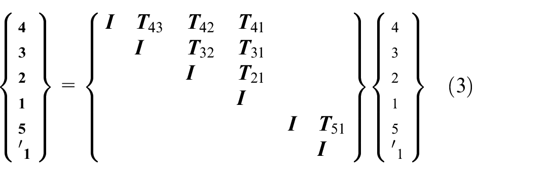
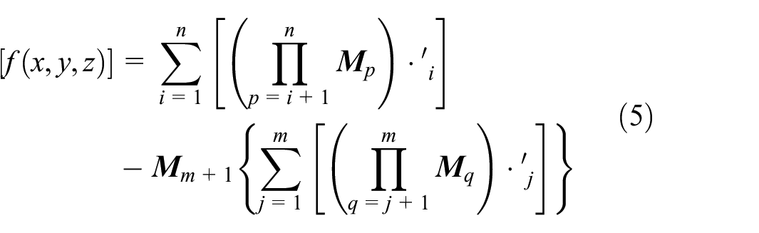
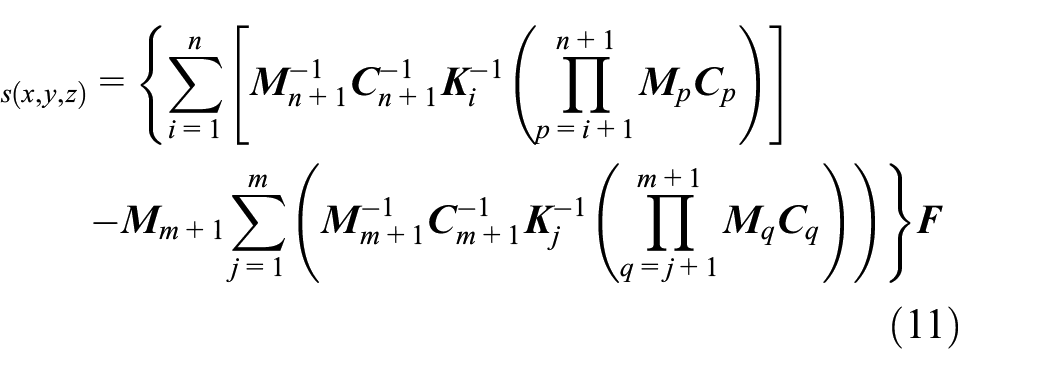
Assuming that there are n components on the tool chain and m components on the workpiece chain, the deformation error of the final machining space at the end of the machine tool can be superimposed and expressed as the error subtraction of the two kinematic chains:

In the formula:
For any component K in a kinematic chain of a machine tool multi-body system, the factors affecting its error
In the formula:
Construction of the machine tool processing space stiffness distribution model
Based on the multi-body system theory, the analysis of the deformation transfer relationship of the machine tool components is completed, and the spatial stiffness of the machine tool is further characterized, and the spatial stiffness distribution model of the machine tool end processing is established.
It is assumed that there is an input equivalent combined load


In the formula:
Solving characterization of spatial stiffness distribution model of machine tool machining
Machine tool component stiffness aggregation representation method
Taking the workbench components of a high-precision Computerized Numerical Control machining center shown in Figure 3 as an example, the EFGH surface is the mounting surface of the workpiece and its supporting fixture in contact with the workbench, which belongs to the bearing end of the workbench components. The load generated by cutting the workpiece will be transmitted through this way and input to the workbench components. The ABCD surface is the installation surface where the slider is in contact with the workbench. The workbench is installed on the bed part through this surface, which belongs to the constraint end of the workbench part. The load is transmitted and output to the bed part through this way. Therefore, A–H is the key geometric feature set that needs to be considered in the workbench components.

Schematic diagram of equivalent aggregation principle for machine tool components.
For any multi-constrained component i with fixed position in the stiffness system of the machine tool, there are n key geometric features ABCDEFGH subjected to external loads, so the stiffness model of the component i can be represented by the stiffness matrix of A–H:

At this time, the size of the stiffness matrix of component i is 6n × 6n.In order to realize the synthesis operation of the spatial stiffness of the whole machine in the later stage, it is necessary to carry out equivalent condensation, and the stiffness characteristics are reflected by the normalized stiffness matrix of 6 × 6. It is assumed that there is an input equivalent resultant force F i in on the loading surface EFGH, and there is an output equivalent resultant force F i out on the constraint surface ABCD. The deformation effect of the input equivalent resultant force F i in and the output equivalent resultant force F i out on component i is exactly the same as that of A–H multi-point loading. Then there is:

In the formula:
Stiffness data acquisition of machine tool parts
Based on the characteristics of the spatial structure of the machine tool and the need for stiffness characterization, a unified machine tool coordinate system should be established first. As shown in Figure 4, it is specified that the x direction of the machine tool coordinate system is along the column stroke direction, the y direction of the machine tool system is along the sliding saddle stroke direction, and the z direction of the machine tool system is along the bed stroke direction. The rotation directions around the x axis, the y axis, and the z axis are a, b, and c, respectively, and the machine tool coordinate system satisfies the right-handed spiral rule.

Schematic diagram of coordinate system for machine tool machining space.
A certain model of high-precision CNC (CNC machining center) machining center in the working state, can be abstractly viewed as a multi-body system consisting of five components: bed, column, table, spindle box, slide saddle. For each component, it can be divided into two categories according to its travel characteristics and constraint conditions. The stiffness modeling methods of the two types of components are generally the same, but the details are slightly different. One kind of multi-constraint parts, headstock, worktable, etc., its main feature is that the load and constraint conditions are complex, but the position of the parts and the load surface are fixed; The other type of multi-position parts, columns, sliding saddles, etc., whose main feature is that the parts contain a structure with variable stroke position, and the external load position of the parts will also move instantaneously along the stroke direction. Compared with the multi-constraint parts, this type of parts also need to discretization continuous stroke when establishing the stiffness model. It should be noted that the bed is connected with the column and the table at the same time, and the column is installed on the bed and fixed. Therefore, the part connected by the bed and the column should be analyzed according to the stiffness characterization method of the multi-constrained parts. The table has a stroke movement on the slide rail of the bed, so the part of the bed and the table should be analyzed according to the stiffness characterization method of the multi-position parts.
Combined with the finite element calculation, the deformation simulation data of the key geometric features of the machine tool components after loading are obtained, and the data are processed and calculated. Finally, the stiffness characterization model of the multi-constrained components is established in the form of matrix.
Taking the machine tool table component as an example, the stiffness characterization model of the multi-constraint component was established. The key geometric features of the workbench components are identified according to the method of stiffness equivalent condensation. Through analysis, it can be seen that in the workbench components, the mounting contact surface of the workpiece and its supporting fixture on the workbench is the bearing end of the component, and the mounting contact surface of the slider on the workbench is the constraint end of the component. Therefore, these two planes are the key geometric features of the table components. After establishing the finite element model of the workbench components, fixed constraints should be applied to the installation surface of the slider at the constraint end of the components, and the unit force (F x , F y , F z ) in the three directions of X, Y, and Z and the unit torque (M a , M b , M c ) in the three directions of A, B, and C should be applied to the working table at the bearing end in turn. Among them, F x , F y , F z are 10,000 N, M a , M b , M c are 10,000 N mm (Figure 5).

Selection of key feature set for workbench.
According to the finite element simulation results shown in Figure 6, the deformation data of the feature points after the workbench is loaded can be obtained, and the workbench flexibility matrix shown in Formula (9) can be obtained. Similarly, the flexibility matrix of other parts of the machine tool can also be obtained by using the same method.

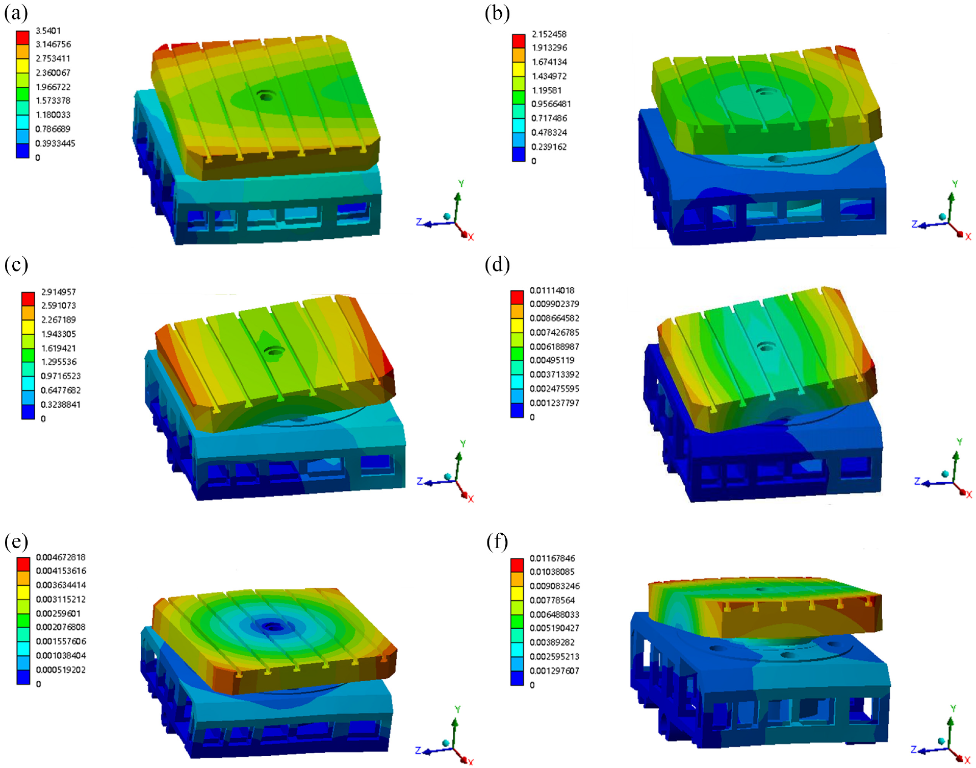
Finite element simulation deformation results of the workbench: (a) deformation in X direction, (b) deformation in Y direction, (c) deformation in Z direction, (d) deformation in A direction, (e) deformation in B direction, and (f) deformation in C direction.
Similarly, stiffness characterization models of headstock, bed (connected to the column) and bed (connected to the table) can also be established in accordance with the methods described in the establishment of workbench stiffness characterization models, as shown in Figure 7.
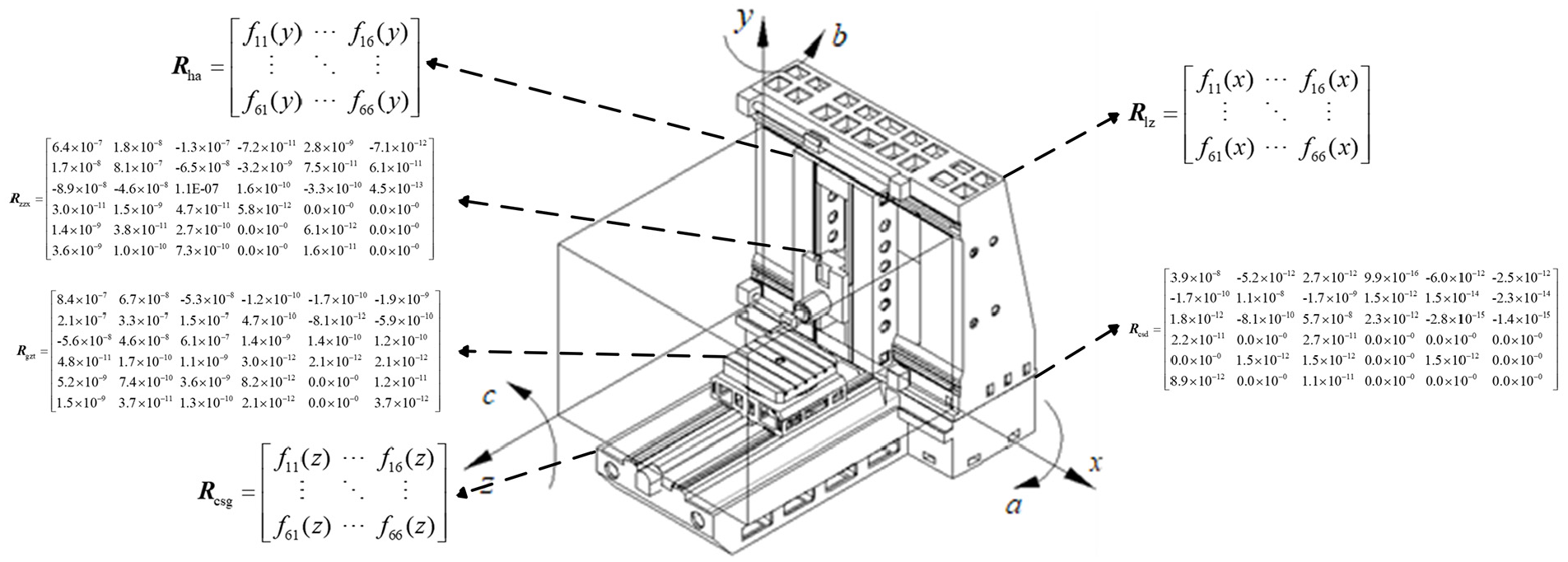
Flexibility matrix diagram.
Analysis of stiffness characteristics of machine tool processing space
The component stiffness matrix and the deformation transfer matrix association, can be obtained by the end of the machine tool machining space stiffness distribution model K, in order to more intuitively reflect the machine tool machining space stiffness of the specific distribution, can be established by the machining space coordinate system, will be obtained from the spatial stiffness distribution model results in the system in the form of the stiffness distribution of the form of the image to be expressed.
It is known that the machining space of the machine tool is a 2000 × 1850 × 2150 mm rectangular body, for the establishment of the machine tool machining space coordinate system for this range: define the slide saddle in the x travel range of the leftmost, the location of the tip of the tool point for the machine tool machining space coordinate system of the X-axis of the zero point; definition of the main spindle box in the y travel range of the lowest, the tip of the tool point of the location of the Y-axis of the zero point; define the worktable in the z travel range, the location of the tool tip of the zero point. When the table is closest to the end of the column in the z travel range, the position of the tool tip is the zero point of the Z-axis.
As shown in Figure 8, the ability of the machine tool to resist x-direction displacement deformation under the action of F x is more sensitive in the direction of z-direction travel, while the change in x- and y-direction travel is not obvious. That is, under the action of F x , if the workpiece clamped to the table moves back and forth on the z-travel of the bed, when the workpiece moves with the table to the zero point of the Z-axis of the machining space coordinate system, the displacement deformation of the machine tool is the largest compared to other positions, when the workpiece moves with the table to the furthest away from the end of the column, the displacement deformation of the machine tool is the smallest compared to other positions.

Sliced diagram of stiffness distribution in machine tool machining space under external loads: (a) x-direction, (b) y-direction, and (c) z-direction.
Similarly, the same method can be used to analyze the stiffness characteristics of the machine tool by plotting slices of the stiffness distribution under other loads.
Machine tool machining accuracy prediction
Machine tool machining accuracy prediction model
In this paper, the milling process of the S-shaped test specimen shown in Figure 9 is selected as the application object. Using the spatial stiffness distribution model of the machine tool established above, the machining accuracy of the component surface of the S-shaped test specimen is predicted by considering the spatial stiffness of the machine tool and the influencing factors of the process system.

The three-dimensional model of the S-shaped test piece.
If the mathematical characterization model of the geometric characteristics of the surface to be processed of the S-shaped test specimen is assumed to be
In the formula:
Equivalent cutting load analysis
Can be based on the “Cutting Dosage Concise Manual” 28 test specimen milling process parameters, combined with the milling process cutting load equivalent conversion of the relevant theoretical formulas, can be solved to calculate the equivalent load.
When the milling process type and process parameters are determined, because the action point of the cutting load is at the tangent point of the tool circumference and the machined surface, this will cause the size and direction of the cutting load to change with the dynamic change of the tool path. On the other hand, due to the unique spatial geometric characteristics of the ruled surface of the S-shaped test specimen, the opening and closing angle between the ruled surface and the bottom surface of the test specimen is not a constant right angle, and the value of the opening and closing angle will change in real time along the direction of the guide line. During the cutting process, the tool circumference is always tangent to the machined surface, and the change of the opening and closing angle will lead to the change of the spatial angle between the tool coordinate system x′oy′ and the machine coordinate system xoy. Therefore, these two factors should be considered comprehensively, and the cutting load should be converted into the equivalent force (F x , F y , F z ) in the three directions of X, Y, and Z and the equivalent torque (M a , M b , M c ) in the three directions of A, B, and C in the machine tool system.
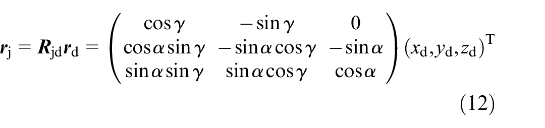
As shown in Figure 10, according to the characteristics of cutting load, the load action point can be selected as the coordinate origin of the tool coordinate system. The direction from the action point to the tool axis is taken as the x′-axis positive direction of the tool coordinate system. The reverse direction of the tool feed direction is taken as the y′-axis positive direction of the tool coordinate system. The direction parallel to the tool axis and deviating from the spindle is the z′-axis positive direction, and the tool coordinate system is established. At this time, there are spatial angles α and γ between the tool coordinate system and the machine tool coordinate system, and the coordinate

Diagrammatic sketch of flank milling of the S-shaped test piece.
In the formula:
The equivalent conversion theoretical formula of cutting load in side milling process in machine system is as follows:
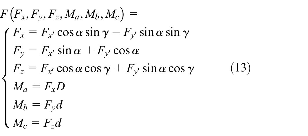
In the formula: D– The distance between the top surface of the S-shaped test piece and the end face of the spindle box is (mm). d– Milling cutter radius (mm).
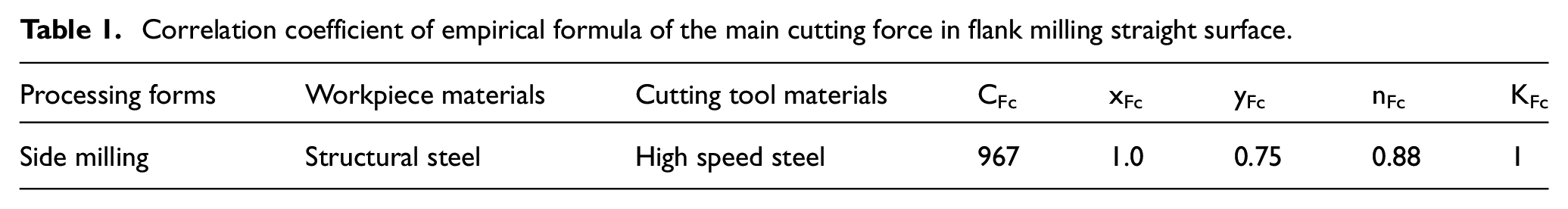
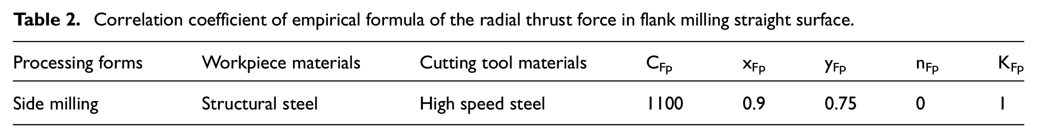
In the side milling of straight grain surface, a cylindrical milling cutter should be selected as the processing tool, tool material selection of high-speed steel, tool diameter selection of d = 40 mm, the number of tool teeth selection of z = 6. At this time, if the cutting speed of v = 20 m/min, the feed is used f = 0.06 mm/r, the depth of cut is used ap = 2 mm, then according to the “Cutting Dosage Concise Handbook,” under the parameters of this process. The selection of correlation coefficients in the cutting load exponential type empirical formulas are listed in Tables 1 to 3:
Correlation coefficient of empirical formula of the main cutting force in flank milling straight surface.
Correlation coefficient of empirical formula of the radial thrust force in flank milling straight surface.
Correlation coefficient of empirical formula of the axial thrust force in flank milling straight surface.

By substituting the coefficient values listed in Tables 1 to 3 into the formula (13), the equivalent load formula (14) of the ruled surface process of the side milling S-shaped test specimen in the machine tool system can be obtained by calculation.

Figure 11 shows the process of determining the size error of the workpiece by using the empirical formula and the stiffness model.

Flow chart.
Machining error prediction and evaluation analysis
According to the clamping position of the S-shaped test specimen in the machine tool coordinate system, the process characteristics of the ruled surface side milling process, and the structural characteristics of the processing equipment, it can be seen that the deformation of the machine tool in the x and y directions has a great influence on the machining accuracy of the ruled surface, and the influence in the z direction is much smaller than that in the x and y directions, which can be ignored.
Therefore, taking the side milling process of the straight-grained face A of the S-shaped test specimen as an example, and taking the clamping angle α = 0° around the X-axis, the machining error of this face is solved, and the specific distribution obtained from the prediction can be shown in Figure 12:

Distribution of prediction errors for the straight-lined surface in side milling process: (a) x-direction and (b) y-direction.
From the above results, it can be concluded that the maximum machining error in the x-direction under this machining process is −204.97 μm, and the maximum machining error in the y-direction is 332.02 μm, and the advantages and disadvantages of the machining accuracy of the machine tool are further evaluated based on the face contour error. As shown in Figure 13, where the color in the figure represents the coordinates of the straight-grained surface A in the z-direction. Along the height direction of the straight surface of the S-shaped test specimen, three inspection intercepts are selected at equal spacing, the intercepts are numbered 1#, 2#, 3# from top to bottom, the spacing of the intercepts is 15 mm, and the distance to the bottom surface of the bottom 3# intercepts is 5 mm. Twenty-five measurement points are selected at equal spacing on each of the intercepts, and the points are numbered 1, 2, … , 24, 25, along the positive direction of the Y-axis, respectively, so that the 75 points selected for the inspection are selected at equal distances. The contouring errors of the 75 selected measurement points are then detected and evaluated.

Selection of measuring points for contour error evaluation of straight surface.
Extract the actual contour coordinates of each measurement point, as well as the machining error of each measurement point in the x and y directions, respectively, as shown in Figure 14:

Comparative analysis of machining error of measuring point of straight surface A: (a) x-direction and (b) y-direction.
The above results are analyzed. In the process of side milling ruled surface A of machine tool, the maximum machining errors in x and y directions will occur near the No.25 measuring point of each section, that is, they all occur at the end of the specimen away from the workbench in the length direction.
The farther away from the worktable clamping position on the ruled surface (near the No.25 measuring point), the greater the contour error is, and the closer to the worktable area (near the No.1 ~5 measuring point), the smaller the error is. However, the error of the part with large curvature of the ruled surface will also increase (near the No.8–11 and No.18–21 measuring points).
There are two reasons for this error distribution: on the one hand, the area near the 8–11 and 18–21 measuring points is the area with the largest curvature of the ruled surface, and the processing difficulty is high; on the other hand, due to the uneven distribution of the spatial stiffness field of the machine tool for side milling, the support stability of the area near the No.25 measuring point far from the clamping position of the worktable is poor.
Experiment
In order to verify the accuracy, feasibility, and validity of the proposed spatial stiffness distribution model of the machine tool, a high-precision machine tool is used as the research object, and the side milling process of the straight grain surface A of the S-shaped test specimen is taken as an example to detect the machining error of the S-shaped specimen by utilizing the coordinate measuring machine.
The material type of the S-shaped test piece is structural steel, and the dimensional parameters are shown in Table 4. In the side milling process of straight grain surface, the cylindrical milling cutter is selected as the processing tool, the tool material is selected high-speed steel, the tool diameter is selected as d = 40 mm, and the number of teeth of the tool is selected as z = 6. At this time, if the cutting speed is adopted as v = 20 m/min, the feed is adopted as f = 0.06 mm/r, and the depth of cut is adopted as ap = 2 mm.
Size parameters of S-shaped specimen.

After calibrating the plane and zero reference of the specimen, according to the pre-written measurement program, the measuring machine automatically completes the measurement of the specimen’s straight surface error, measuring 75 test points. The process of measuring the test piece is shown in Figure 15.

Three coordinate measuring machine measuring specimen process.
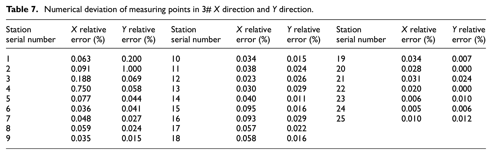
The X and Y direction deformation errors of the S-shaped specimen measured by the three-coordinate measuring instrument are compared with the predicted X and Y direction deformation errors. As shown in Figure 16 and Tables 5 to 7, it can be seen that the deformation error measured by the three coordinate measuring instrument at 75 test points has the same trend as the deformation error predicted by the machining accuracy, and the larger deformation error is the two-segment curve part of the S-shaped specimen. The reason is that the bending radian of the ruled surface in these two regions is larger.

Comparison of deformation error between prediction and test.
Numerical deviation of measuring points in 1# X direction and Y direction.

Numerical deviation of measuring points in 2# X direction and Y direction.

Numerical deviation of measuring points in 3# X direction and Y direction.
Conclusion
In this paper, based on the deformation transfer relationship of multi-body system, a spatial stiffness distribution model of machine tool end machining is established. The stiffness condensation theory and finite element method are used to solve the stiffness distribution information of machine tool efficiently. The established spatial stiffness distribution model of machine tool is used to predict the machining accuracy of the component surface of the S-shaped test specimen of machine tool milling. The following conclusions are drawn:
Based on the theory of multi-body system, taking a high-precision CNC machine tool as an example, according to the spatial assembly relationship of the machine tool, the topological structure of the multi-body system of the machine tool is described by the low-order body array method. The spatial stiffness of the machine tool is further characterized, and the spatial stiffness distribution model of the end processing of the machine tool is established;
The stiffness polycondensation theory and finite element analysis method are used to obtain the equivalent stiffness matrix of the components of the machine tool to characterize its stiffness characteristics, so as to efficiently solve the stiffness distribution characteristics of the machine tool processing space, and intuitively show the stiffness distribution characteristics of the machine tool processing space;
Based on the characterization model of the spatial stiffness distribution of the machine tool and the mathematical characterization model of the geometric characteristics of the S-shaped specimen surface, combined with the equivalent conversion theoretical formula of the cutting load under the machining trajectory of the machine tool, the prediction model of the machining accuracy of the machine tool is established, and the profile error of the side milling ruled surface of the specimen is predicted;
Taking a high-precision machine tool as the research object, the contour error detection test of S-shaped specimen is carried out. The measurement results are consistent with the prediction results of machining accuracy in Chapter 4. The accuracy, feasibility, and effectiveness of the spatial stiffness distribution model of the machine tool are verified by experiments.
Footnotes
Handling Editor: Divyam Semwal
Declaration of conflicting interests
The author(s) declared no potential conflicts of interest with respect to the research, authorship, and/or publication of this article.
Funding
The author(s) disclosed receipt of the following financial support for the research, authorship, and/or publication of this article: National Natural Science Foundation of China Youth Science Foundation Project (51905328).