
Abstract
Saw-tooth chip generated from hard turning is one of the most distinguishing features with conventional turning process. The presented work aims to contribute an extensive understanding the formation mechanism and main parameters of saw-tooth chips in oblique hard turning of 90CrSi hardened tool steel (60–62 HRC). The effects of dry, Al2O3 nanofluid MQL, Al2O3/MoS2 hybrid nanofluid MQL conditions on the serrated chip formation were experimentally investigated in terms of chip morphology, chip color, segment spacing, serrated segmentation frequency, and shear angle. The obtained experimental results indicated that, due to the better cooling and lubricating performance of nanofluid and hybrid nanofluid, the shear angles ϕ increase about 91.73% and 94.88% respectively when compared to dry cutting, which makes the formation of saw-tooth chip more favorable. Moreover, the analysis of microstructure image of the back side of chip proves the better lubrication from ball roller and tribo-film formation of Al2O3 and MoS2 nanoparticles. Based on the chip morphology analysis, the shear angle ϕ, the degree of chip segmentation on the top side in the chip’s transverse section K2, and the chip deformation coefficient in the transverse section K3 should be used as the additional criterions to evaluate the frictional improvement in cutting zone.
Keywords
Introduction
In modern production nowadays, machining processes are not only required to reach high accuracy, surface quality, and productivity, but also must ensure the environmental friendliness. 1 Among them, hard machining technology has attracted much attention and has been studied by scientists and manufacturers, especially in the field of molds, automotive industry, and so on. 2 Direct cutting of high hardness materials (≥45 HRC) has opened up new technological solutions, which contribute to support/replace the grinding process. 3 Besides, dry hard machining has completely eliminated the problem of environmental pollution from using cutting oils, which is also one of the main disadvantages of the grinding process. In hard machining technology, hard turning was first applied in the automotive industry. However, this technology has not been so far widely used in the production practice due to high cutting forces and cutting temperatures, leading to low tool life and deterioration of machined surface quality. In addition, the formation of serrated chips is closely related to cutting force, cutting temperature, and machined surface quality. 4 One of the earliest studies on the saw-tooth chip formation originated from the work of Kazuo Nakayama, 5 who coined “saw-tooth chip” for the name of chip generated from hard cutting process due to the shape of its cross section. Based on this study, the chip formation mechanism in hard machining was investigated and developed.6,7 The first simple model of cyclic cracking initiation during serrated chip formation in hard turning was proposed by Shaw and Vyas, 8 which is a contribution to the understanding of the mechanism of saw-tooth chip generation. Elbestawi et al. 9 proposed the theory of fracture mechanics built to study the saw-tooth chip in cutting of hardened materials. Joshi et al. 10 found that the formation of crack on the free face of the chip has developed toward the cutting tool nose, which has a negative effect on the tool life. Fracture propagation suffers by the greatest impact from the cutting speed. Dolinšek et al. 11 made an experimental study on the serrated chip formation, chip morphology, and tooth spacing in hard cutting of the hardened steel X63CrMoV51. The author pointed out that there was a tight relationship among serrated chip parameters with cutting speed ranges, especially in high cutting speed region. An extensive study on the saw-tooth chip formation mechanism in high-speed milling of SKD11 and S136 hardened steel (51, 62 HRC) indicated that cutting speed had strong influences on the work material hardness and local cutting temperature of the shear band. 12 The shear strain and strain rate during saw-tooth chip formation could be predicted by establishing the geometric model. The strain rate hardening also plays a main role and is strongly influenced by the high cutting speed. 13 Also, the enormous heat from hard cutting zone will cause the phase transform and white layer formation on the serrated chips in finish hard milling of AISI H13 tool steel (50 HRC). 14 The adiabatic shear is the distinguishing feature to form the distinctive white layer in hardened material cutting. 15
In addition, the cutting temperature can be estimated by the proposed analytical method, and the chip color can be predicted by the analysis of the oxidation layer on the chips generated. Tang et al. 16 carried out the orthogonal dry hard turning of AISI D2 tool steel in different cutting speeds and hardness (40, 45, 50, 55, and 60 HRC) to investigate the formation process of serrated chips. The authors stated that the degree of segmentation, tooth spacing, and shear angle were strongly affected by the work material hardness. The higher values of cutting speeds and material harness will cause the cutting temperature to become higher. The simulation model was built and chip parameters were investigated to study the serrated chip formation in micro cutting of Ti6Al4V. 17 Nevertheless, the very high cutting heat and limitation in increasing cutting speed values adversely influence the engineering economic effectiveness of hard machining processes in practice. The solutions for these problems are to lubricate and cool the work/tool interface. The application of novel cooling lubrication techniques like Minimum Quantity Lubrication (MQL), cryogenic cooling, and MQL using nano cutting oils has contributed to improve the hard cutting performance. Uysal and Jawahir 18 experimentally studied the serrated chip formed in orthogonal turning of AISI 304 stainless steel, a difficult-to-cut material, under dry, flood, MQL, and cryogenic cooling conditions. The findings indicated that the frictional shear stress in contact zone was lowest under MQL environment, but the highest was in dry cutting. In addition to that, the tool-chip contact length reduced slightly and more favorable chip shape forms with the application of coolant or lubricant, which helps to increase cutting speed. Also, the most outstanding contribution of this work is a novel slip-line model for serrated chip formation in orthogonal hard turning. Zhao et al. 19 made an experimental study on serrated chip formation of Ti-6Al-4V titanium alloy under dry and cryogenic turning. The authors concluded that the cryogenic condition contributes to the ease to form the adiabatic shear band by the shear slip of the material in the main deformation zone, which is beneficial to the chip breaking. The superior cooling effectiveness of cryogenic cutting resulted in the increase of height ratio and serrated pitch compared to dry condition. Duman et al. 20 studied ultrasonic vibration assisted orthogonal turning process under MQL condition and claimed that MQL ultrasonic-assisted cutting brought out the improvement in chip breakability and more favorable chip shapes compared to dry condition. Besides, compared to dry and ultrasonic-assisted machining conditions, the significant reduction of cutting forces and cutting temperature as well as the improved surface quality were achieved by using MQL ultrasonic-assisted machining.
Vegetable oils were proven to be an alternate, biodegradable and feasible solution for cutting fluids for clean manufacturing activities. They are mainly composed of fatty acid and triglyceride -COOH in the fatty acid molecules and -COOR in triglyceride both belong to polar groups, which gives them excellent lubrication property. 21 On the other hand, due to their higher viscosity, vegetable oils are the suitable candidate for the base oil when nanoparticles are suspended. The applications of nanoparticles enriched in vegetable oils were reported in many studies and the findings all agreed with the improvement in machining efficiency and meet the environmental friendly requirements. The additives of graphene nanoparticles in vegetable oil for MQL ultrasonic-assisted turning of Ti-6Al-7Nb biomedical titanium alloy was proven to enhance the machining efficiency in terms of cutting force, cutting temperature, material removal rate, and surface roughness. 22 Sharma et al. 23 made a critical review on the applications of nanofluid in machining and concluded that the nano cutting oil shows better tribological properties compared to its base oil. The positive machining performance was achieved by the growing nanoparticle concentration, but more attention should be made on the nanoparticle types, size, and shape. Each type of nanoparticles has their own morphology and property, so it determines what cooling and lubricating mechanism would create in the cutting zone. Sharma et al. 24 explored the novel application of Al2O3/MoS2 hybrid nanoparticle enriched cutting fluid in MQL hard turning of AISI 304 steel. A fixed volumetric proportion of 90:10 was used for Al2O3/MoS2 hybrid nano cutting oil, and the different nanoparticle concentrations (0.25, 0.75, and 1.25 vol.%) were studied for Al2O3 nanofluid and Al2O3/MoS2 hybrid nanofluid. The obtained findings indicated that Al2O3/MoS2 hybrid nanofluid brought out the better results in terms of cutting forces and surface roughness than Al2O3 mono nanofluid. Yıldırım et al. 25 made a comparison on the tribological characteristics of MWCNT/Al2O3, Al2O3/MoS2, and MWCNT/MoS2 biodegradable-based hybrid nanofluids in MQL turning of hardened AISI 420 (55.5 HRC). The authors also claimed that the hybrid cutting oils show the better machined surface quality than mono nano cutting oil, pure oil, and dry cutting environments. In the surveyed conditions, the best surface topography was reported in case of MQL hard turning using Al2O3/MoS2 hybrid nanofluid. He et al. 26 investigated the lubrication performance of Al2O3/MoS2 hybrid nanofluid and pointed out the significant decrease in friction force and wear rate. Şirin and Kıvak 27 demonstrated the impact of the hybrid nanofluid MQL method on the surface quality improvement and the reduction of cutting forces, cutting heat, and tool wear in milling of Inconel X-750 superalloy. Hexagonal boron nitride (hBN)/graphene hybrid nanofluid (0.1% hBN + 0.1% graphene) employed in MQL method improved the cooling lubrication due to the formation of a protective tribofilm and the increase in lubricant viscosity when machining Ti6Al4V alloy. 28 From there, it can be clearly observed that the trend of combining a type of nanoparticles with high hardness and good thermal conductivity to create the rolling mechanism with a type of nanoparticles with a layered structure playing a role in the tribo-film formation 29 to develop hybrid nano cutting oils. Hence, Al2O3/MoS2 hybrid nanofluid was developed and applied in this work. In addition, from above literature review, the deep study for understanding the mechanism of saw-tooth chip formation in oblique hard turning under hybrid nanofluid and nanofluid MQL is limited. Accordingly, the main aim of this study is to investigate the effects of dry cutting and MQL using Al2O3/MoS2 hybrid nanofluid and Al2O3 nanofluid on the saw-tooth chip formation in hard turning of 90CrSi (60–62 HRC). The paper content was structured by the following sections. Section “Introduction” is introduction, which provides a comprehensive background on the existing research related to saw-tooth chip formation, specifically under nanofluid and hybrid nanofluid MQL conditions. Section “Experimental procedures” is the Experimental procedures to present how the experiment was set up and carried out. Section “Results and discussion” is results and discussion to provide the measured data and analysis of saw-tooth chip parameters (chip morphology, chip color, tooth spacing, serrated segmentation frequency, and shear angle). Finally, Section “Conclusion” is conclusion of the study, which summarizes the significant findings, limitations, and future works.
Experimental procedures
Workpiece sample
The 90CrSi steel is low alloy tool steel and has been commonly used in the metal cutting field due to high strength and hardness, good oxidation resistance, and wear resistance. Its applications include machine parts, bolts, screws, shafts, gears, piston shafts, and so on. Hence, in this work, the 90CrSi tool steel samples with the hardness values of 60–62 HRC were used with the diameter of 40 mm. The chemical composition and mechanical properties of 90CrSi tool steel are shown in Tables 1 and 2.
Chemical composition of 90CrSi steel (wt%) according to DIN standard.

Mechanical properties of 90CrSi steel according to DIN standard.

Experimental set up
The diagram shown in Figure 1 presents the experiment set up and the measurement process. Hard turning experiments were conducted on the CS-460x1000 Chu Shing lathe (Pin Shin Machinery Co., LTD, Taichung city, Taiwan). The MQL nozzle with the designation of NOGA MiniCool MC1700 was set up to directly spray the flank face of CBN cutting tool. The pressure regulator MAR401 series and flow control valve MSC200-8A were used to adjust the air pressure and air flow rate for MQL system. The main objective of this work is to study the mechanism of serrated chip formation in hard turning with different cooling lubrication environments, so the cutting conditions were fixed at cutting speed of 160 m/min, feed of 0.12 mm/rev, and cutting depth of 0.12 mm based on the previous work.30,31 The hard turning trials were conducted under dry, Al2O3 nanofluid MQL, and Al2O3/MoS2 hybrid nanofluid MQL. The grain sizes of Al2O3 and MoS2 nanoparticles are 30 nm, and they were suspended in the soybean oil to prepare the Al2O3/MoS2 hybrid nano cutting oil and Al2O3 nano cutting oil in 1 h using the Ultrasons-HD ultrasonic homogenizer (JP Selecta, Abrera (Barcelona), Spain) at 40 kHz frequency and 600 W maximum power to obtain a homogeneous mixture. 32 The obtained Al2O3/MoS2 hybrid nano cutting oil (mixing ratio of 8:2) and Al2O3 nano cutting oil had the nanoparticle concentrations of 1.0% and 0.7%, respectively.30,32,33 To avoid possible agglomeration of nanoparticles, the fresh samples of nanofluid and hybrid nanofluid were prepared for each test and used immediately.
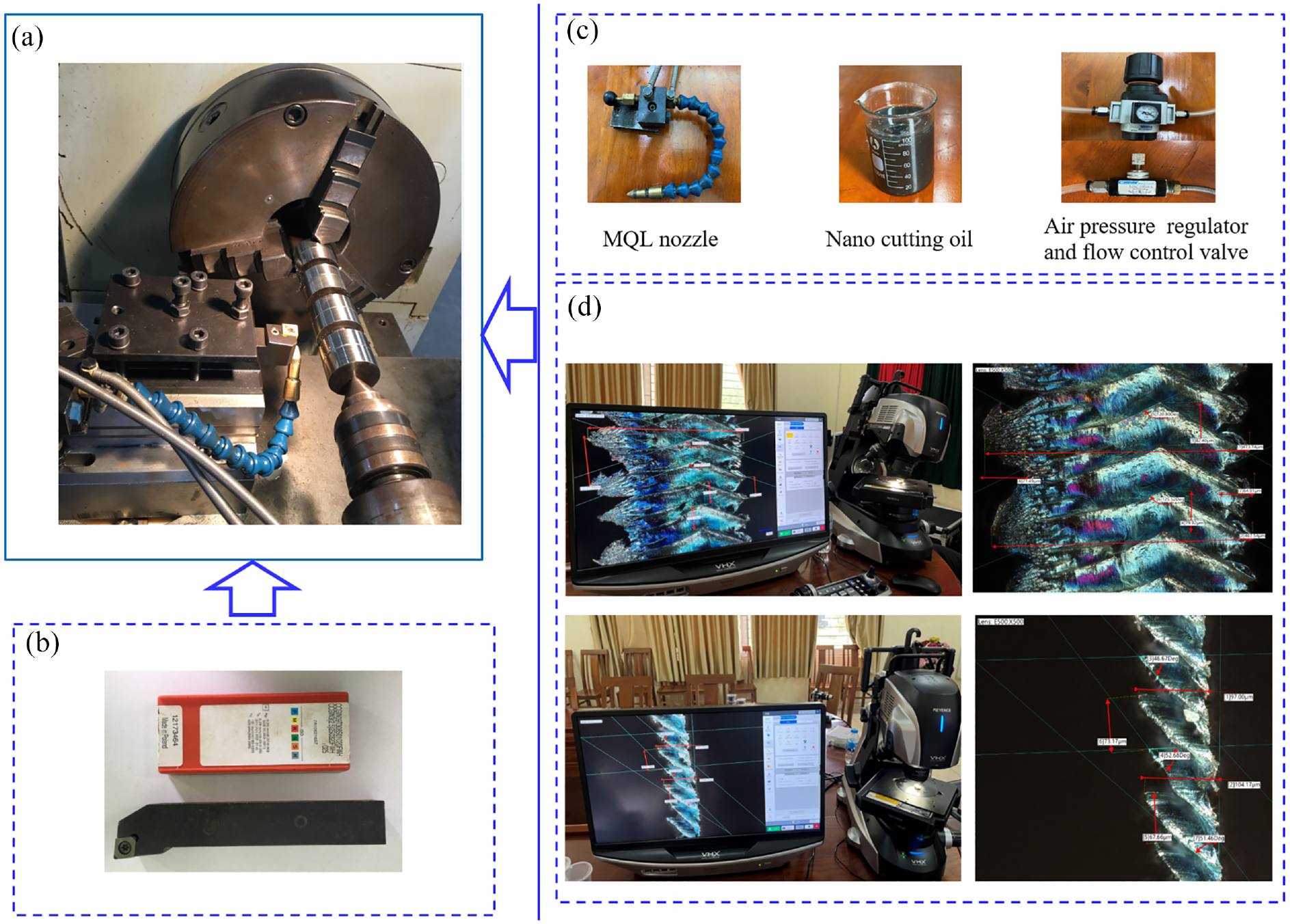
The diagram of experimental set-up and measurements: (a) experimental set up, (b) CBN cutting insert, (c) MQL system, and (d) Keyence digital microscope VHX-7000 series used for the study of saw-tooth chip parameters.
CBN cutting tool
In this paper, CBN inserts with the designation of CCGW 09T308S 01020 FWH (type: 80° positive rhombic inserts with 2 CBN tips) containing 60% CBN composition in volume with 1–3 μm grain size were chosen according to the literature 16 and shown in Figure 2. They can provide shock resistance and very high wear resistance and are widely applied for machining hardened steel, sintered metals and high temperature alloys. 30 The tool nose is 0.8 mm with 2.2 mm cutting edge length, the rake angle is −20°, and the clearance angle is 7°. The CBN inserts were made by Sandvik Coromant, Sweden and mounted on the tool holder type with the designation SCLCR 2020 K-09 (Seco Tools Vietnam, DC Tower, 111D, Ly Chinh Thang Street, Ward 7, District 3, HCM City, Vietnam).

CBN cutting inserts.
Results and discussion
The cutting diagram and chip formation process of oblique hard turning model under hybrid nanofluid MQL are shown in Figure 3.

The cutting diagram of hard turning hard under Al2O3/MoS2 HF MQL condition: (a) chip formation process when observed on the top side of the chip’s transverse section, (b) chip formation process when observed in the chip’s longitudinal section, and (c) description of Al2O3/MoS2 hybrid nano cutting oil components in cutting zone.
In this case, the nose radius r is 0.8 mm, cuts with feed rate f = 0.12 mm/rev and depth of cut a p = 0.12 mm, which means that the values of feed rate and the depth of cut are small, so the tool cuts directly in the AOE arc, the point O can be considered the center of the cutting edge (Figure 3(a)). Hence, the point O is considered to be the set point of the total cutting force F and is the center of the flank wear (this content will be clarified in the survey on cutting force and tool wear).
Figure 3(b) interprets the penetration model of hybrid nano cutting oil into the cutting zone, the saw-toothed chip formation model during hard turning in general and the general shape of the serrated chip. The hybrid nano cutting oil is sprayed directly onto the tool flank face. When penetrating in the cutting zone, a part of the cutting oil goes onto the rake face to reduce the friction between the rake face and the generated chip.
Figure 3(c) illustrates the Al2O3/MoS2 hybrid oil film in the cutting zone consisting of (1) base oil particles (soybean oil) forming a hydrodynamic lubricating oil mist; (2) near-spherical shaped Al2O3 nanoparticles act as rollers; (3) MoS2 nanosheets with good lubricating properties to create thin lubricating films on the tool surface and machined workpiece.
The main lubrication mechanism here is a combination of the based oil film, the roller mechanism of Al2O3 nanoparticles, 32 and the film formation from MoS2 nanoparticles.33,34 In addition, because Al2O3 and MoS2 nanoparticles both have good thermal conductivity, they contribute significantly to reduce cutting heat. 23 The effect of hybrid oil film is to improve friction conditions and cutting performance (chip formation, cutting force, tool wear, machined surface quality, etc.). To clarify the effectiveness of hybrid oil film, the content of this section is only evaluated through the chip formation process and there is a comparison between using Al2O3/MoS2 HF MQL compared to dry and Al2O3 NF MQL conditions.
The machining diagram here is an oblique turning, so in addition to analyzing the chip formation model and chip structure along the longitudinal section as in the orthogonal turning diagram.
18
The coefficient K1 is affected by material cracks during chip formation along the chip’s longitudinal section, reflecting the shear angle ϕ. Because the shear angle
The saw-tooth chip formation mechanism
The model of serrated chip formation along the side of the chip in hard turning is presented in Figure 3(b). At the point C, the material at the free surface begins to be pushed up and assumed in the CD direction parallel to the resultant cutting force F. The shear crack starts from point D and grows down along the sliding plane DO to the rake face of the tool. When the tool moves, the chip slides along the crack surface until a new crack forms at point D′. In machining hard materials, the so called “saw-tooth” chips are formed due to the fracture of the work material.
Crack initiation appears on the work surface when the work material reaches the limit shear strain, so the fracture phenomenon dominates the chip formation process. During the formation of saw-tooth chips, three phenomena appear: (1) hardening due to the chip being subjected to large plastic deformation, (2) softening due to high cutting heat, and (3) chip hardening due to high cutting heat combined with discontinuous cutting. 2
KEYENCE Digital Microscope VHX-7000 series provides the 4K high accuracy and is capable of capturing high resolution images and measurement data for inspection and failure analysis. In each investigated cooling lubrication condition, generated chips were collected and measured directly on KEYENCE Digital Microscope VHX-7000 series. The high resolution image of chip morphology along the edge side and some basic parameters are shown in Figure 4. The fractures are clearly seen on the work material, which is a distinguishing characteristic of saw-tooth chips. Some characteristic parameters of chips include4,12:
(1) The shear angle ϕ, is formed by the sliding direction OD′ (Figure 3(b)) with the underside of the chip and is the angle that determines the crack location to form saw-tooth chips. ϕ depends mainly on parameters such as workpiece hardness, cutting speed, rake angle γ, tool wear, and so on. When the cutting conditions are reasonable and the saw-tooth chip formation process is favorable, the shear angle ϕ decreases; otherwise, it increases.
(2) ’The angle ϕ1 is the tip angle of saw-tooth chip, and the influence of machining parameters on the angle ϕ1 is similar to the shear angle ϕ.
(3)
(4) The mean chip thickness H.
(5) The mean chip thickness at local shear deformation h.
(6) The degree of segmentation


The side of saw-tooth chip generated from hard turning under Al2O3/MoS2 HF MQL condition.
The larger the chip segmentation
However, the chip here is kept in its original shape and the process of capturing and measuring the dimensions is done on a digital microscope, so the dimensional measurement of h is difficult and inaccurate and the measured values of H obtained are not much difference, so this indicator could not be used for evaluation.
Analysis of saw-tooth chip structure from the top side
The chip formation process and some parameters for evaluating serrated chips’ transverse section on the top side (free surface) with the model of external cylindrical surface turning with vertical tooling are shown in Figure 3(a). Typical images of the top and back surfaces of serrated chips’ transverse section in dry hard turning and Al2O3/MoS2 HF MQL hard turning are shown in Figure 5.

The structure of the top and back sides of the serrated chip’s transverse section in Al2O3/MoS2 HF MQL hard turning: (a) the top side and (b) the back side.
The material side flow is a distinguishing phenomenon occurring in hard turning operations. It is the plastic flow of brittle material due to the compression effect of the workpiece material between the flank face of the cutting tool and the machined surface when the undeformed chip thickness (UCT) is less than a minimum value hmin.2,14 The cutting diagram in Figure 3(a), the part of the cutting edge directly involved in cutting is the AOE arc, assuming that each fracture cycle, the material turned into chips is the area AOEO1 (the crossed out part in Figure 3(a)). Due to the material side flow effect during hard turning, when there is longitudinal tool movement, the material will flow to both sides of the OO1 axis (Figure 3(a)). The serrated chip structure is formed with characteristic peaks and fringes (A1 A2) as shown in Figures 3(a) and 5(a). The observation of the chip’s transverse section will help evaluate the influence of cooling lubrication conditions (HF MQL, NF MQL, and Dry) on the friction properties between the chip and the rake face of the cutting tool.
From the top surface of the chip’s transverse section in Figure 5(a), it clearly shows that the serrated chip here is made up of layers sliding over each other due to the process of the work material fracture through sliding planes with the serrated tips located on the OO1 axis with the angle at the top is β. Due to the flow effect of the hard material, the material side flow to both sides of the OO1 axis to create a chip structure with characteristic patterns A1, A2 as shown in Figure 5. Some characteristic parameters of the chip for evaluation include14,35:
(1) Saw-tooth tip angle β (°).
(2) Average width of chip B (mm).
(3) Average width of chip at local shear deformation b (mm).
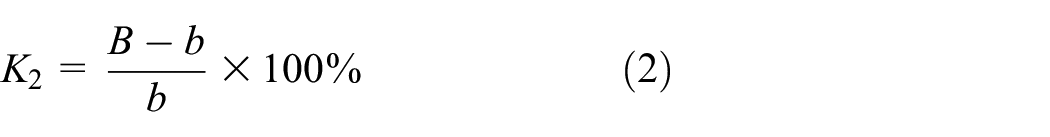
(4) Degree of chip segmentation on the top side in the chip’s transverse section K2:
(5) Chip deformation coefficient in the chip’s transverse section
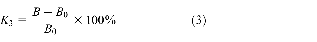
Where B is the average width of chip (mm), b is average width of chip at local shear deformation (mm), B0 is the average width of the undeformed cut layer (mm), which is the diagonal of AE of the area of material that turns into chips after each sliding cycle. Due to cutting with nominal feed rate f = 120 µm/rev and nominal depth of cut a p = 120 µm, the size of B0 is determined by the formula:

If the friction coefficient between the chip and the rake face of the tool is smaller, the degree of chip segmentation on the top side K2 and chip deformation coefficient K3 in the chip’s transverse section are larger. That indicates the improvement of cutting conditions and the more favorable conditions for serrated chip generation.
Evaluation through other factors
In addition to an overall assessment through observing chip morphology images as above, a number of criteria can be used to quantitatively evaluate the influence of Al2O3/MoS2 HF MQL technique on the chip formation process of serrated chips. For the parameters on the chip’s longitudinal section as analyzed above, the degree of segmentation K1 is not used and other parameters do not have much difference except the shear angle ϕ. Therefore, only the shear angle ϕ can be used as a criterion. Based on the chip’s transverse section, the degree of chip segmentation on the top side K2 and chip deformation coefficient K3 can be utilized as the criteria.
Measurement results of some basic parameters and some evaluation coefficients are given in Table 3. The charts of some parameters and coefficients under different cooling lubrication conditions are shown in Figure 6.
Serrated chip parameters under different cooling lubrication conditions.

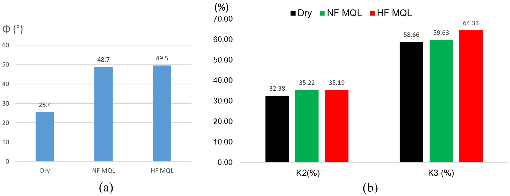
The serrated chip parameters and coefficients under different cooling lubrication conditions: (a) shear angle ϕ (°) and (b) degree of chip segmentation on the top side in transverse section K2 and chip deformation coefficient in the transverse section K3.
With all three criteria mentioned in Table 3 and Figure 6, it clearly reveals that Al2O3/MoS2 HF MQL and Al2O3 NF MQL environment contributed to enhance the hard turning performance to create the more favorable conditions for serrated chip formation when compared to dry cutting due to smaller shear angle ϕ, larger coefficients K2 and K3. If the criterion of shear angle ϕ is used, Al2O3/MoS2 HF MQL contributes to enhance the cutting conditions in terms of more favorable serrated chip formation than NF MQL. The shear angle ϕ under Al2O3/MoS2 HF MQL is 49.50°, increasing about 1.64% and 94.88% compared to Al2O3 NF MQL (48.70°) and dry machining (25.40°; Figure 6(a)). Also, Al2O3 NF MQL improves the cutting conditions significantly compared to dry machining with the shear angle increasing about 91.73% compared to dry condition (25.40°). When using the K2 coefficient as a criterion, the use of Al2O3/MoS2 HF MQL (K2 = 35.19) has no difference with Al2O3 NF MQL (K2 = 35.22) but has significant improvements compared to dry machining. K2 increased by 8.77% with that of dry condition (K2 = 32.38; Figure 6(b)). In case of using K3 coefficient, Al2O3/MoS2 HF MQL condition indicates the best machining performance with K3 = 64.33, which is about 7.88% and 9.67% higher than those of Al2O3 NF MQL (K3 = 59.63) and dry condition (K3 = 58.66), respectively (Figure 6(b)).
In addition to that, compared to Al2O3 NF MQL, Al2O3/MoS2 HF MQL exhibited the improvement in the serrated chip formation but not much. In hard turning process, the material flow greatly influences the deformation of the work material and the roughness formation. It depends mainly on the friction between the flank face and the workpiece and between the rake face and the back of chips. Under Al2O3/MoS2 HF MQL, the combination effects of “ball roller” mechanism from Al2O3 nanoparticles36,37 and tribo-film formation from MoS2 nanosheets improved friction conditions in the cutting zone.32,34 As a result, the friction on the contact faces is significantly reduced, so the process to generate serrated chips is more favorable. This process is also reflected by the smaller shear angle ϕ, the easier chip deformation (i.e. K3 is larger), and the larger degree of segmentation K2. The Al2O3 NF MQL condition is less effective than Al2O3/MoS2 HF MQL due to single interaction created by Al2O3 nanoparticles.
Chip morphology and chip color
The serrated chip morphology images taken on the VHX-7000 digital microscope for dry turning and hard turning under Al2O3/MoS2 HF MQL and Al2O3 NF MQL condition are shown in Figures 7 to 9. It can be obviously indicated that the generated chip form is the saw-tooth chips. The general chip morphology such as cracks on the side face, chip shape, and the roughness on the top side are basically the same. The differences in chip morphology observed here include:

Serrated chip morphology in dry turning: (a) the chip’s longitudinal section; and (b) the top sides of the chip’s transverse section.

Serrated chip morphology in Al2O3/MoS2 HF MQL hard turning: (a) the chip’s longitudinal section; and (b) the top sides of the chip’s transverse section.

Serrated chip morphology in Al2O3 NF MQL hard turning: (a) the chip’s longitudinal section; and (b) the top sides of the chip’s transverse section
In hard turning, the chip color is purple, resulted from the Si component in 90CrSi steel combined with high temperature (Figure 7). Under Al2O3 NF MQL environment, the chip has the straw yellow color, which indicates the lower temperature due to the better cooling lubrication characteristics (Figure 9).36,38 For Al2O3/MoS2 HF MQL condition, the chip generated has a dark blue color because Al2O3/MoS2 hybrid nano cutting oil exhibits the higher performance in cooling lubrication when compared to Al2O3 NF MQL. 38
The characteristic roughness of the serrated chip formed on the A1 side symbolized in Figure 3(a) for all three different lubrication conditions is basically not much different. The main difference is the characteristic roughness on the A2 side. For Al2O3/MoS2 HF MQL condition, the folds are smaller than those in dry and Al2O3 NF MQL (Figures 7(b1)–9(b1)).
In dry and Al2O3 NF MQL turning (Figures 7(b2) and 9(b2)), the slip marks between the serrated layers are clearly observed as straight lines parallel to the sliding direction of chip OO1 (Figure 3(a)) and have the characteristic purple and straw yellow colors. Under Al2O3/MoS2 HF MQL (Figure 8(b2)), the slip marks are also formed but not clear, proving that the sliding process between material layers when forming serrated chips takes place more easily due to the effective impact of hybrid nano cutting oil. 39
Figure 10(a) shows the back side of the chip generated from dry cutting. Because the back face of the chip slides on the front of the cutting edge, the back surface is shiny and has many scratches and especially peeling marks. Figure 10(b) shows the back side of the chip in Al2O3/MoS2 HF MQL hard turning. It can be seen that the back surface is shiny and smooth with no peeling marks observed. The reasons are that the hybrid nano cutting oil contributes to reduce the friction between the chip back and the front of the cutting edge. 40 Figure 10(c) presents the chip back obtained from Al2O3 NF MQL hard turning. The back surface is similar to that in Al2O3/MoS2 HF MQL hard turning, proving the improvement in lubricating performance resulted in the additives of Al2O3 nanoparticles,41,42 but a thin oil film is observed.

The back side of the chip in hard turning of 90CrSi steel under different cooling lubrication conditions: (a) dry, (b) Al2O3/MoS2 HF MQL, and (c) Al2O3 NF MQL.
Limitations of the study
This study has potential limitations. It has only been studied with an Al2O3/MoS2 hybrid nanofluid with a mixing ratio of 8:2 with the nanoparticle concentration of 1%. The obtained results of Al2O3/MoS2 hybrid nanofluid MQL were only compared with Al2O3 nanofluid MQL and dry turning, but not yet compared with MoS2 nanofluid MQL. The other types, grain sizes, morphologies of nanoparticles should be developed and investigated. Last but not least, the effects of tool wear, tool life, and cutting temperature on cutting force have not been evaluated.
Conclusion
In this article, the oblique hard turning process was conducted to 90CrSi tool steel to investigate the chip formation mechanism under dry, Al2O3 nanofluid MQL, and Al2O3/MoS2 hybrid nanofluid MQL. The main contribution can be summarized as follows:
The mechanism of saw-tooth chip formation and its parameters in oblique hard turning with MQL conditions using nanofluid and hybrid nanofluid were analyzed. The obtained results indicate that Al2O3 nanofluid MQL and Al2O3/MoS2 hybrid nanofluid MQL create the more favorable condition for saw-tooth chip formation when compared to dry cutting. These findings are reflected by larger shear angle ϕ and larger coefficients K2 and K3. Specifically, compared to dry condition, the increases of ϕ, K2 and K3 are 91.73%, 8.77%, and 1.65% under Al2O3 NF MQL and 94.88%, 8.68%, and 9.67% under Al2O3/MoS2 HF MQL, respectively. These parameters should be used as the criterions to evaluate the frictional improvement in hard machining.
The serrated chip formation process and material side flow in hard turning still mainly depend on work material hardness and cutting speed. Based on the analysis, the uses of Al2O3 nanofluid MQL and Al2O3/MoS2 hybrid nanofluid MQL also cause the significant influences. From there, these results will serve as a basis for further studies on cutting force, tool wear, and machined surface quality, which can be directly used in industrial applications.
The microstructure image of the back side of chip’s transverse section was analyzed to prove the better lubrication resulted in the mechanism of “ball roller” and tribo-film formation of Al2O3 and MoS2 nanoparticles. The coefficients K2 and K3 could be used as the supplementary parameters to study the serrated chip formation in hard machining.
In further work, the deeper investigation should be made to study the influence of the other mixing ratios of Al2O3/MoS2 hybrid nano cutting oil, nanoparticle concentration, grain size to find out the optimal parameters. In addition, other types of hybrid nanofluid like hBN/MoS2, Al2O3/CuO, CuO/MoS2, etc. should be developed in the different based oil for further development in machining difficult-to-cut materials.
Footnotes
Handling Editor: Andreas Rosenkranz
Declaration of conflicting interests
The author(s) declared no potential conflicts of interest with respect to the research, authorship, and/or publication of this article.
Funding
The author(s) disclosed receipt of the following financial support for the research, authorship, and/or publication of this article: The work presented in this paper is supported by Thai Nguyen University of Technology, Thai Nguyen University, Vietnam.