
Abstract
To further improve the accuracy of sensorless control at medium and high speeds for permanent magnet synchronous motor (PMSM) and expand its applicability, this paper proposes a new scheme that uses a sliding mode observer and a frequency-locked loop (FLL) for control. The combination of the super-twisting algorithm (STA) and fractional calculus algorithm (FCA) is applied to the observer, which improves the convergence speed and accuracy. In response to the limitations of phase-locked loops (PLLs), a second-order generalized integral frequency-locked loop (SOGI-FLL) is introduced into the control system to be compounded to form a novel control system with compensation, which filters the signal while achieving accurate tracking of rotor position information. Finally, a series of experiments were conducted to compare the performance of the proposed control scheme with conventional control schemes. The superiority and feasibility of the sensorless control scheme were verified through experimental results on a permanent magnet synchronous motor platform.
Keywords
Introduction
Motivation
Given the escalating societal demand for energy and the global push toward reducing reliance on fossil fuels, numerous countries are actively promoting the advancement of new energy-driven industries as a cornerstone for long-term development.1–3 Within the realm of electrical drives, PMSMs have emerged as the preferred choice due to their inherent advantages, such as high efficiency, elevated power density, and exceptional reliability. These qualities have garnered considerable attention, making PMSM technology a focal point of extensive research and application across diverse industrial sectors and everyday life. As a result, PMSMs are becoming pivotal players in the ongoing transition toward sustainable and efficient energy solutions.4–8
In motor control, conventional approaches often depend on sensors for closed-loop control. However, achieving the desired control outcomes necessitates precise rotor position information. Traditional methods employ mechanical position sensors such as photoelectric encoders and transformers for this purpose. Nevertheless, the incorporation of such sensors introduces complexities and elevated costs in both hardware and software design, adversely impacting system operability. Additionally, the spatial constraints and the introduction of additional devices pose challenges to the working environment of the motor. Moreover, sensor sensitivity to external interferences further compromises system stability and robustness. Hence, sensorless control emerges as a practical solution to address these challenges.9–11
Related researches
Based on field-oriented control (FOC), many methods with excellent control effect have been produced, such as model-free control,12,13 model-predictive control,14,15 and sensorless control, which has been widely used in real scenes.
The inception of sensorless control schemes for PMSMs dates back to the 1970s. Presently, it finds widespread application in both industrial and domestic settings.16–18 These schemes are typically categorized into two classes based on methodologies and principles. The first category is based on the saliency of motors and is particularly suited at low speeds.19–24 In this case, the back-electromotive force (back-EMF) of the motor is small and can be ignored. By introducing high-frequency signals, it becomes possible to effectively derive signals containing essential rotor position information. Traditionally, injection signals can be subcategorized into rotational signal injection and pulsation signal injection based on their characteristics. Moreover, pulsating signals can be further classified into sinusoidal waves, square waves, and triangular waves.23,25–31
The second category of sensorless control methods is model-based and is particularly effective within medium to high speed ranges. In this case, rotor position tracking is accomplished through either a stator flux observer or sufficiently substantial back-EMF containing rotor information.32–37 Model-based methods often exhibit a certain reliance on accurate motor parameters, and deviations of parameters can lead to control inaccuracies. Consequently, certain investigations emphasize the precision of parameters in scheme design and propose online estimation strategies. Model-based methods can be further classified into three primary categories: model reference adaptive systems (MRAS), extended Kalman filter (EKF), and sliding mode observer (SMO). Each method possesses characteristics owing to differences in principles. MRAS demands high accuracy in motor parameters, making online parameter estimation a common practice.38–42 EKF, while exhibiting strong filtering capabilities for robust rotor position tracking, entails greater computational complexity and challenges in tuning and implementation within industrial settings.43–48 SMO stands out for its robustness, rapid convergence, fewer parameter requirements, and ease of implementation, rendering it a popular choice in sensorless control.49–51
Sliding mode control represents a unique form of nonlinear control system with a characteristic of switching. The control effect of this method hinges on the design of sliding mode surfaces and the choices of sliding mode gains. Choosing the appropriate gain is crucial, as an excessively small sliding mode gain coefficient can slow down convergence speed, while an excessively large one can induce significant system chattering.52–55 Various studies have sought to address chattering in sliding mode control. Some have explored the replacement of the sign function in the control law with alternative s-shaped functions to mitigate chattering.56,57 Others have devised adaptive laws for the sliding mode gain constant to optimize control effects.58–60 High-order observers have been proposed to replace traditional SMOs, simultaneously resolving chattering issues while enhancing convergence speed and control accuracy.49,61 Additionally, the introduction of fuzzy algorithms to replace the original switching function, ensuring output continuity while attenuating chattering is another direction for optimizing SMO. Through this method, the parameter fitness and robustness of the control system were improved.62,63 Traditional sliding control laws often contain integer-order terms, but studies suggested that controllers incorporating fractional-order terms outperform integer-order controllers, significantly suppressing chattering generated by sliding mode algorithms. FCA is introduced into different control modules in the closed loop of the motor in Hazeleger et al. 64 and Sun et al., 65 which improved the selection range and flexibility of parameters, and enhanced control performance and the effect of suppressing chattering of the system. The feasibility and superiority of fractional order (FO) observers have also been demonstrated in relevant research.
After acquiring the back-EMF that contains rotor position information, it is essential to analyze it to determine the motor’s speed and position. Conventional analytical methods often rely on the arctangent function, which can introduce substantial computational errors. 66 To address this issue, many approaches have adopted PLL or FLL for signal analysis, demonstrating their feasibility and effectiveness in enhancing accuracy.67,68
Contributions
In this paper, the design and the improvement of the rotor position information acquisition method for PMSM is taken as the research objective, to propose a solution for sensorless control at medium and high speeds. Specifically, research is conducted on the sensorless control system of PMSM at medium to high speeds, and the conventional scheme based on SMO and PLL is optimized. The main contributions of this paper can be listed as follows:
Considering that the extended back-EMF signal containing rotor position information obtained by conventional SMO observer contains more harmonics and interference signals, it has been optimized. By extending STA to FO and combining it with FCA, FO-STSMO is proposed to suppress chattering and improve the accuracy of the obtained signal.
In addressing the limitations of traditional phase-locked loop systems in accurately tracking rotor position, this paper proposes a novel FLL-based structure with compensation to enhance performance. Drawing inspiration from FLL applications in power grids, a dual second-order generalized integrator-FLL (DSOGI-FLL) is developed to effectively filter the extended back electromotive force. Additionally, this structure is combined with an auxiliary PLL to achieve precise estimation of both speed and rotor position.
Organization of this paper
In Section “Analysis of conventional SMO,” an analysis of the conventional sensorless control scheme based on the establishment of the PMSM mathematical model is conducted. Section “Analysis and improvement of ST-SMO” introduces ST-SMO and FCA, which are combined to propose FO-STSMO. The main content of Section “Analysis and improvement of PLL” consists of the analysis of PLL and the introduction of SOGI-FLL to address its limitations, resulting in the design of a novel structure with compensation for rotor information estimation. The feasibility and performance of the proposed sensorless control scheme are experimentally verified in Section “Experimental validation.” Finally, the content of this paper is summarized in Section “Conclusions.”
Analysis of conventional SMO
Mathematical model of PMSM
To conduct a dynamic analysis of PMSM, it is usually necessary to establish a mathematical model.69–72 To facilitate the design of sensorless control schemes, under ideal conditions, the voltage equation of three-phase PMSM in a stationary reference frame (SRF) can be expressed as follows:

where u α , β , L d , q , i α , β , ω e , and E α , β are stator voltage, stator inductance, stator current, electric angular velocity, and extended back-EMF, respectively. p represents the differential operator.
E α , β can be expressed as follows:

where θe,
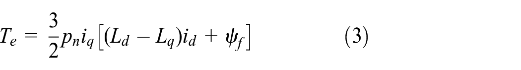
The electromagnetic torque equation can be expressed as follows:
Under this condition, the mechanical motion equation of the motor can be expressed as follows:
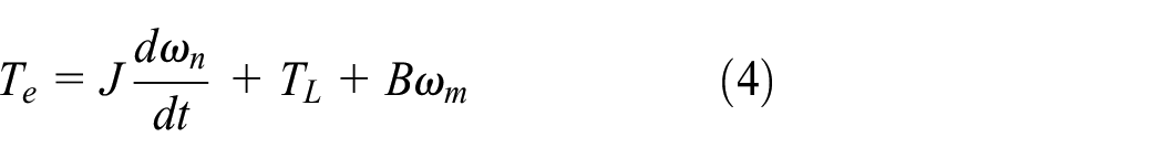
where J, B, TL, and ω m are the moment of inertia, damping coefficient, load torque, and mechanical speed, respectively.
Basic theory of conventional SMO
To simplify the application of SMO for observing the extended back-EMF, (1) can be reformulated into the following current state equation:


The sliding surface of conventional SMO is chosen typically as follows:

where

The error equation of stator current is presented as follows:

The sliding mode control law is chosen typically as follows:

where k is the gain of SMO. When the system converges to the preset sliding surface, the observed extended back-EMF is expressed as follows:

As sliding mode control introduces high-frequency chattering near the sliding surface, these disturbances are also contained in the resulting extended back-EMF. The extended back-EMF, initially calculated through the arctangent function, expresses the rotor angular position estimation as follows:

Based on (12), the rotor speed can be determined through differential operation as follows:

The block diagram of conventional sensorless control is shown in Figure 1.
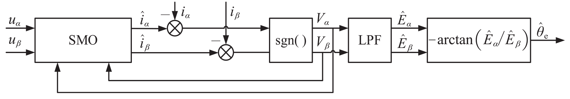
Block diagram of conventional sensorless control principle based on SMO.
Limitations of conventional SMO
The accuracy of conventional SMO hinges on the choice of the SMO gain; thus, the selection of the sliding mode gain in SMO design is critical. In conventional sensorless control at medium to high speeds, the rotor position and speed information are typically calculated using the arctangent function. This approach introduces calculation errors from the digital signal processor and amplifies the estimation errors between signals, significantly affecting the control accuracy of the motor’s speed and position. Therefore, incorporating a low-pass filter (LPF) before rotor information estimation becomes imperative to eliminate high-frequency harmonics within the extended back-EMF. However, this addition introduces a delay in rotor estimation, further compromising system accuracy. 73
These limitations adversely affect both the observation and analysis of subsequent signals, diminishing the overall reliability and precision of SMO. Consequently, the subsequent section of this paper proposes optimizations to address these drawbacks.
Analysis and improvement of ST-SMO
Mathematical model of PMSM
The STA can suppress HF chatterings, thereby enhancing the dynamic performance and convergence speed of the observer. 74 Its inherent robustness contributes to the overall system robustness. The STA can be expressed as follows:

where x1,2, σ, k i , and ν i are constants related to motor parameters, sliding mode parameter, sliding mode gain satisfying Lyapunov stability requirement, and perturbation terms, respectively. Typically, the value of σ is set to 1/2.
Under the Lyapunov stability criterion, the gain of ST-SMO must satisfy the following conditions 75 :

The perturbation terms must be globally constrained by the following conditions:

where δ1 is a positive constant. Extracting the estimated rotor position with the current as the state variable involves obtaining the extended back-EMF of ST-SMO, as follows:
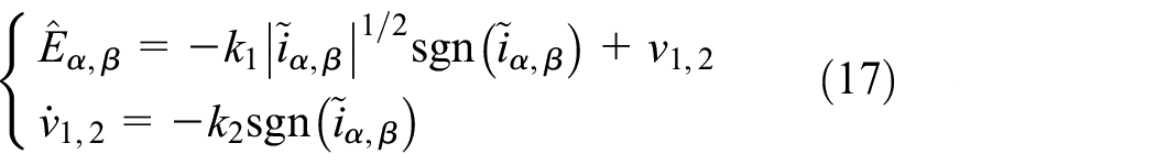
In the presented equation, within ST-SMO, result continuity is maintained by multiplying a continuous term. This action significantly reduces system chatterings and enhances overall system performance, achieved through either a sign function or an integration operation.
Implementation of FCA
FCA is an efficient mathematical modeling tool that can accurately portray system model information. In addition, the fractional order provides more options and possibilities for the FO controller. Many studies have shown that the controller with the FO integral term outperforms the integer order, and the fractional order is also useful for suppressing the controller chatterings. Therefore, introducing FCA into ST-SMO can improve the accuracy of the observer and expand its applicability. It can make a better choice between robustness and anti-interference, making the system have better static and dynamic characteristics.76,77
A generalization of the fractional order operators can be written as follows:

where t0 and t are the bounds of the calculus of the operator
In this paper, Riemann-Liouville definition is used, which can be written as follows:
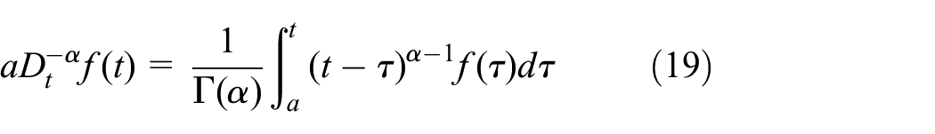
where α and Γ(α) are the order of calculus, and Gamma function, respectively.
The fractional-order dynamical system is written as follows:

where x, u, and ε are state variables, input, and output, respectively. The variables in the equation satisfy 0 < λ < 1 and
The control law of the FO-STSMO algorithm can be written as follows:

where k n , k s , k l 1, and k l 2 are positive constants. To ensure that the system converges in a finite time, the following conditions for the above four parameters also need to satisfy the following conditions 78 :

where
The sliding mode observer is designed as follows:

The error equation of fractional stator current can be written as follows:

In fractional order, when the system reaches the steady state, the extended back-EMF can be obtained as follows:
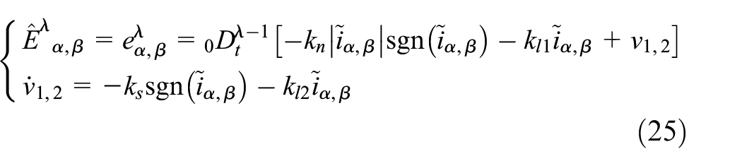
The extended back-EMF obtained from (25) can be subsequently analyzed to extract information about the rotor.
Stability analysis of proposed observer
In control theory, stability implies the system’s ability to maintain a bounded state amid external disturbances or initial condition changes, avoiding divergence or uncontrolled fluctuations. A key objective in designing a sliding mode observer is to swiftly observe and converge to a predefined sliding surface within a finite time. This rapid convergence property enhances the observer’s sensitivity to dynamic system changes, ensuring timely and precise estimation of the system’s state. A stable sliding mode observer effectively reduces observation errors to zero within a finite time, guaranteeing a reliable system state estimation. This is vital for real-time control and monitoring applications, particularly in scenarios with stringent requirements for system behavior. Hence, demonstrating the stability of the observer is typically imperative.
To prove that the observer is stable, substitute (21) into (20) to written as follows:

By integrating (26), the equation can be written as follows:

Through mathematical transformation, (27) can be rewritten as follows:

where
The Lyapunov equation is rewritten in a quadratic form as follows:

In (29), the two matrices can be represented as follows:

The derivative for the Lyapunov function is written as follows:

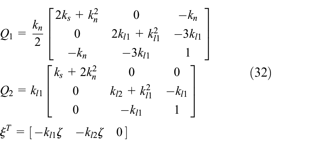
In (31), the three matrices can be represented as follows:
Considering the range of uncertain terms in (28), the following relationship can be found:

In (33), the matrices can be represented as follows:

When the coefficients in the matrix all satisfy (22), the following inequality holds:

Equation (35) can be rewritten in the following form:

where
According to the above analysis, it can be seen that FO-ST-SMO can converge in a finite time.
Analysis and improvement of PLL
Mathematical model of PMSM
Considering the adverse effects of the introduction of an arctangent function during the acquisition process of rotor information, the estimation of most motor positions is achieved through a PLL.
According to the different internal functions, PLL is divided into three parts, phase detector (PD), loop filter (LF), and voltage controlled oscillator (VCO). The schematic diagram of normalized PLL is shown in Figure 2.

Schematic diagram of normalized PLL.
In an ideal situation, after the PI calculation, the rotor speed
As we can see from Figure 2, the rotor position open-loop transfer function of conventional PLL can be written as follows:

Based on (37), the error transfer function of the system can be obtained as follows:

The use of a tangent function and a large number of division calculations in PD results in a much higher harmonic content in the estimation of the rotor information. In addition, the steady-state error of PLL is analyzed in the case of three basic input signals: θ1, θ2, θ3, which represent phase step, speed step, and speed ramp, respectively. The three input signals mentioned can be represented as follows:

where a, b, and c are the gain of phase step, speed step, and speed ramp, respectively. The phase steady-state errors of PLL under the three input signals can be obtained by using the final value theorem as follows:
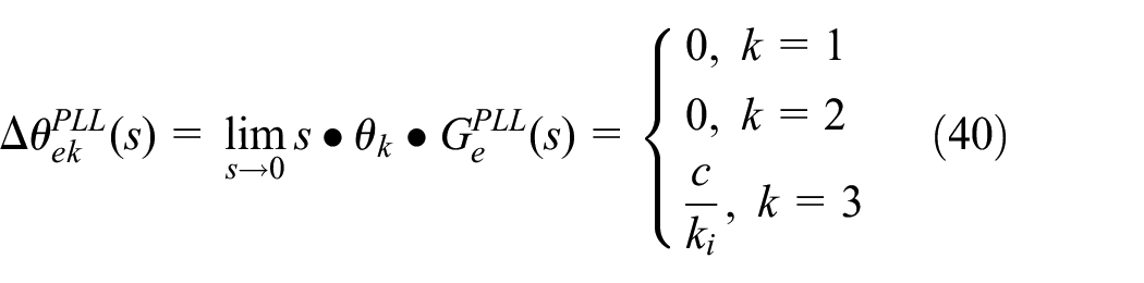
It can be seen in (40) that PLL achieves no error in estimating the position of the rotator when the input signals are phase step and speed step. However, since it is a type-II control system when the input signal is a speed ramp, the input cannot be tracked accurately, and there will be a limited error in the steady state. As the gain coefficient c of the speed ramp increases, the steady-state error also increases. By increasing k i , this error can be reduced, but excessive k i can lead to excessive bandwidth in the PLL system, resulting in errors in estimating harmonics during the process. Therefore, PLL has some limitations in practical applications where frequent start-stop or speed changes are required.
To address the limitations of PLL, a feasible approach is to improve the control system to form a type-III system, which is also the subsequent research content of this paper.
Introduction of SOGI-FLL
The SOGI-FLL is a widely adopted signal processing method in grid and power control applications. Differing from PLL, this algorithm primarily focuses on detecting and tracking signal amplitude and frequency. It excels in isolating positive and negative sequence components of voltage in the grid, even in the presence of noise, harmonic interference, and phase loss. Given the effectiveness of SOGI-FLL and the challenges associated with obtaining rotor position information in sensorless PMSM control, it is incorporated into the proposed sensorless control scheme. The structure diagram of SOGI-FLL, depicted in Figure 3, comprises two functional parts: second-order generalized integral quadrature signal generator (SOGI-QSG) and FLL.

Schematic diagram of SOGI-FLL.
As shown in the figure above, the transfer function of SOGI can be expressed as follows:


Based on the transfer function, the Bode diagram is further plotted in Figure 4.
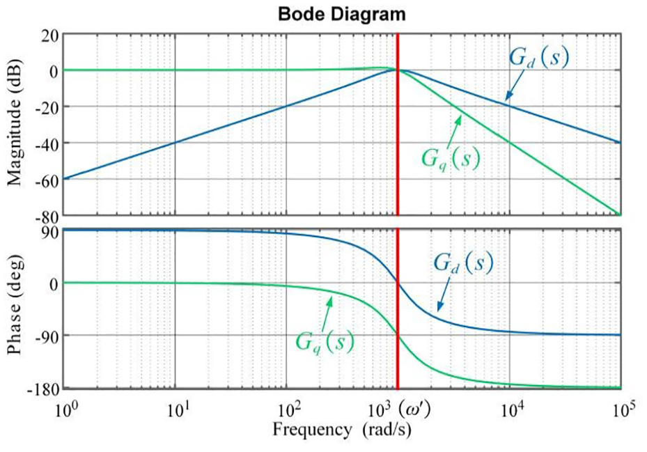
Bode diagram of SOGI.
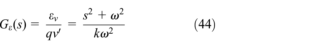
From the amplitude-frequency characteristic curve, it can be seen that when the resonant frequency
The effect of FLL is to estimate the motor speed. The frequency error variable
The SOGI-FLL structure allows it to greatly reduce harmonic interference in the signal, achieving precise tracking of the fundamental signal frequency, which can be used to accurately estimate the back electromotive force and speed of the motor.
Proposal of a novel FLL
In the current sensorless control schemes, the mainstream uses PI-based observers or PLL to estimate one of the rotor position or speed information and subsequently obtains another information through calculus operations. However, the use of LPF can lead to the attenuation of the amplitude of the extended back-EMF and the generation of phase delay. Therefore, the accuracy of information estimated in the conventional scheme is poor.
Based on the analysis in Part B, a novel dual SOGI-FLL with compensatory PLL (DSOGI-FLL-CPLL) is proposed to address this situation. The proposed DSOGI-FLL-CPLL structure primarily comprises two parts. The block diagram of the proposed scheme is shown in Figure 5.
Block diagram of DSOGI-FLL-CPLL.
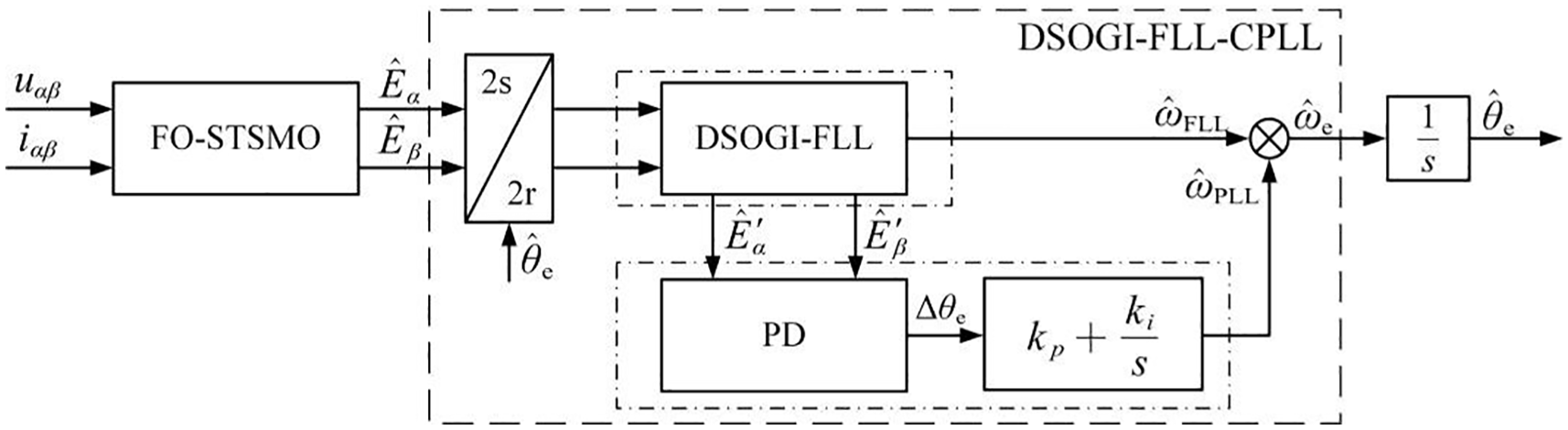
The first part utilizes DSOGI-FLL to handle the estimated extended back-EMF, including interference signals obtained from the observer, and derives the estimated speed information. To accurately obtain the extended back-EMF, considering that the frequency of the extended back-EMF estimated in SRF is the same, two SOGI modules and one FLL are used to process the extended back-EMF and achieve the estimation of speed. The block diagram of this structure is shown in Figure 6.

Block diagram of DSOGI-FLL.
In the second part, a forward speed estimation channel is added to the proposed FLL-based structure to achieve fast velocity tracking. In this module, speed information is primarily estimated using a modified FLL. The output of the PLL serves as a compensation signal to eliminate errors in the tracking process, thereby enhancing accuracy and performance.
After improvement, the small signal model of the proposed FLL-CPLL is shown in Figure 7. From the figure, it can be seen that after adding a feedforward channel, the control system has become a type-III system. Compared with the conventional type-II PLL, it can achieve tracking of speed ramp input.
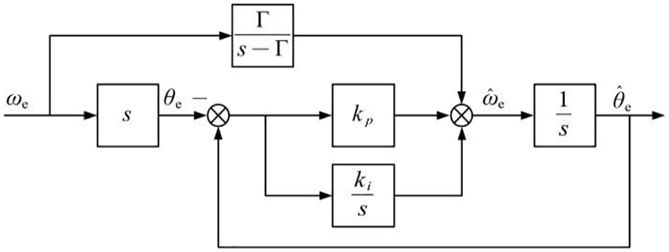
Small signal model of proposed FLL-CPLL.
Experimental validation
To verify the superiority of the proposed sensorless control scheme, an experimental comparison between the sensorless scheme using the proposed sensorless scheme and the conventional SMO-PLL structure is performed. The control scheme in this paper is implemented through a development board based on TMS320F28335. The experimental results are communicated to a PC and plotted by MATLAB. Given the suitability of the sensorless control method based on back-EMF for medium and high speeds, we selected the speed testing range to be 50% or more of the rated speed in our experiments to achieve the desired control effect. Therefore, considering the applicability of SMO-based sensorless control, the motor is initially started using an I/F strategy and then verified after stabilization.
The proposed scheme, validated through the experimental platform, is implemented using a FOC strategy as depicted in the block diagram in Figure 8.
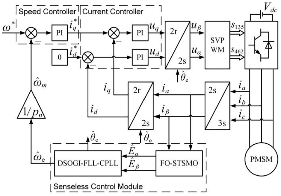
Block diagram of the sensorless control system for PMSM.
The experimental setup comprises essential components including an oscilloscope, inverter, control module, voltage regulator, torque sensor, PMSM, and torque motor. Figure 9 illustrates the configuration of the experimental platform and equipment. Table 1 provides the parameters of the PMSM used in the experiment.
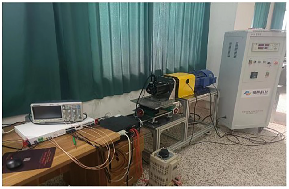
Experimental platform and equipment composition.
PMSM and control system parameters.

Observer-based sensorless control is primarily employed for medium and high speeds of the motor, and Section “Analysis and improvement of PLL” of this paper theoretically analyzes the steady-state error of the system with three basic input signals. Given that the motor typically does not undergo step changes in rotor position under normal operating conditions, the main focus of this experiment is to verify and analyze the dynamic performance of the motor when subjected to changes in operation conditions within a reasonable speed range. In the experimental testing, we first compared the observation and signal analysis effects of the conventional SMO-based scheme, the ST-SMO-based scheme, and the proposed scheme. After partial validation, we compared the control effects of the most widely used traditional SMO-based sensorless control scheme under various operating conditions to further validate the superiority of the proposed scheme.
Considering that the sensorless approach based on back-EMF is mainly suitable for medium to high speeds, we have limited the speed in the experiment. Specifically, the control system is tested in the mechanical speed range of 1500–2500 rpm, considering the rated speed of experimental PMSM.
Verification of effectiveness of proposed observer
To verify the efficacy of the proposed observer in obtaining the extended back-EMF, a comparison was conducted between the processed signals in the conventional SMO, the proposed observer, and ST-SMO at a constant speed of 1800 rpm. The results are presented in Figure 10.
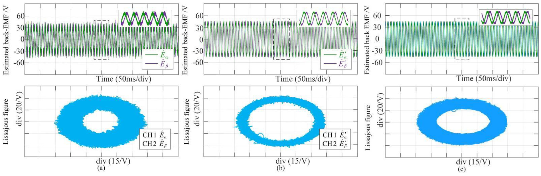
Verification of the effectiveness of the proposed observer: (a) conventional SMO, (b) proposed observer, and (c) ST-SMO.
As shown in the above figure, it can be seen from (a) of Figure 10 that there are significant harmonics in the back-EMF observed through conventional SMO, which will seriously affect the accuracy of sensorless control. Furthermore, by comparing (b) and (c), we can still observe that although ST-SMO has been improved to achieve relatively ideal observation accuracy and harmonic suppression, it can still be seen from the analysis of the Lissajous figure that there are still many harmonics. On the contrary, the proposed observer has been improved based on ST-SMO, using the FCA to make the observer more flexible and accurately adapted to the system, resulting in better suppression of harmonics and achieving the best observation accuracy among the three observers.
Verification of effectiveness of proposed PLL
To verify the superiority of obtaining rotor position information in the proposed scheme, we observed the motor back-EMF through ST-SMO and compared the speed estimation with different PLL/FLL under the condition of speed variation. At 0.3 s, the speed ramped from 1800 to 2000 rpm for 0.3 s and maintained for 0.6 s, then increased to 2400 rpm after 0.3 s ramping. The comparison results are shown in Figure 11.

Verification of the effectiveness of the proposed FLL: (a) conventional PLL, (b) conventional SOGI-FLL, and (c) proposed FLL.
From the figure, it can be seen that all three structures can achieve speed tracking. As the most commonly used structure, although conventional PLL performs well in speed tracking, there are still some steady-state errors, which are particularly evident in the process of ramp signal tracking. SOGI-FLL improved on this aspect but did not eliminate it, which is reflected in the estimation of larger pulsations when tracking ramp signals. The proposed FLL combines the advantages of the above two and has a feedforward adjustment, making the system have stable and excellent tracking performance throughout the entire tracking process.
Comparison of steady-state performance
To verify the superior control performance of the proposed scheme under steady-state conditions, a comparison is made between the speed, speed error, rotor position error, and currents of d-q axis of the motor using both the conventional scheme and the proposed scheme. The speed is set to a constant of 2000 rpm, and the torque load is set to a constant of 10 N m. The results are illustrated in Figure 12.
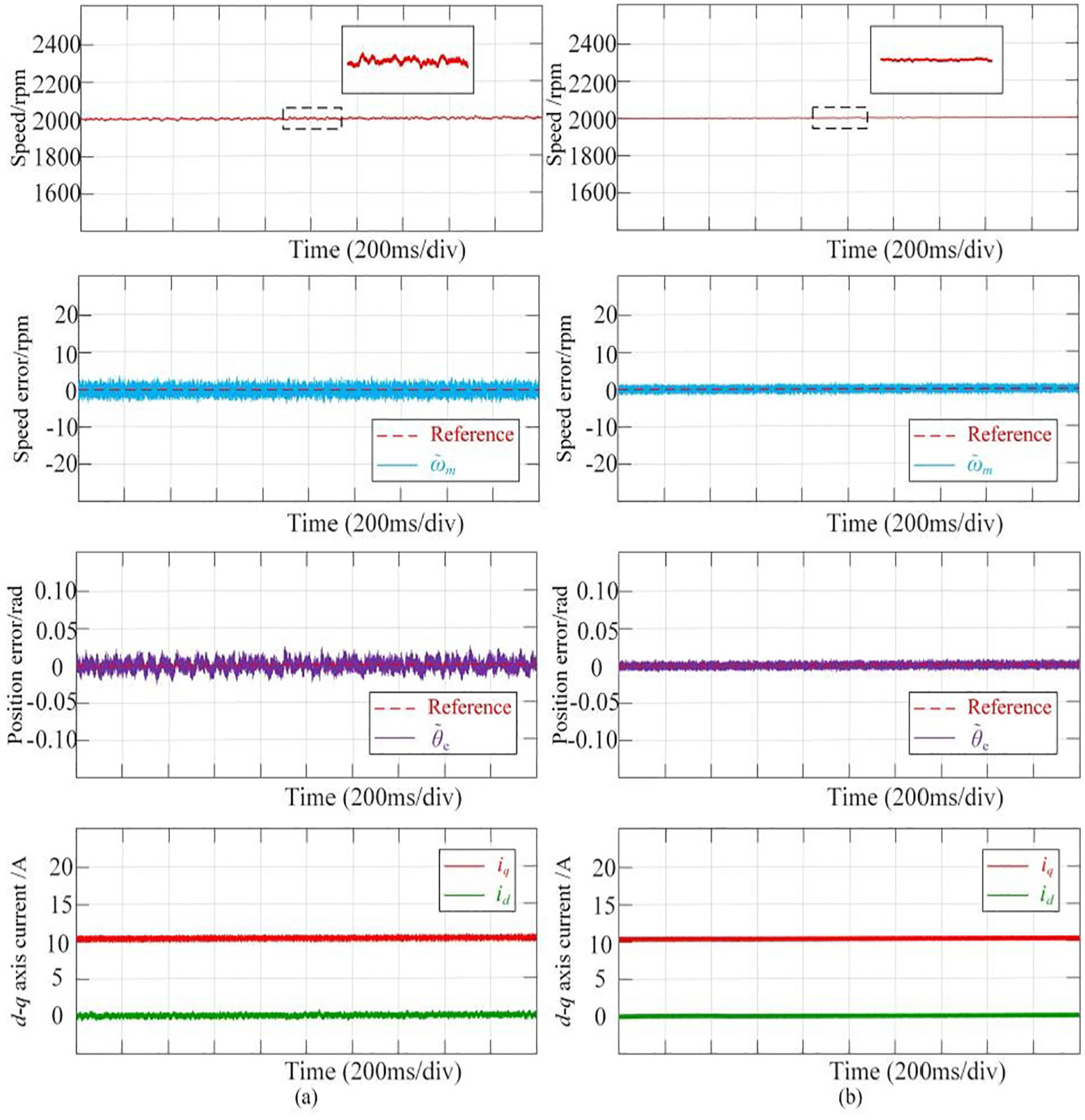
Experimental results under varying speed step conditions: (a) SMO-PLL scheme and (b) proposed scheme.
As shown in the above figure, both the conventional and the proposed scheme can achieve stable control of speed. However, specifically, due to the limitations of observer and signal processing in the conventional control scheme, there have been significant fluctuations in the speed, with the maximum speed fluctuation being 17 rpm. The proposed scheme has a better speed control effect and controls the maximum speed fluctuation at 5 rpm. In terms of speed error, the proposed scheme has a speed error of only 2 rpm, which is lower than the conventional scheme that produces a speed error of 4 rpm. In terms of rotor position error, the conventional scheme exhibits significant chattering, with a maximum error of 0.025 rad. The proposed scheme not only weakened chattering but also has an estimation error of only 0.013 rad, which has better accuracy. In addition, the superiority of the proposed scheme in steady-state control performance is also reflected in the d-q axis current.
Comparison of dynamic performance
Verify the dynamic performance of the proposed scheme using reference speed changes. The reference speed changes at 0.4, 0.8, 1.2, and 1.7 s, as shown in Figure 13. In the first stage, the speed remains constant at 1800 rpm. In the second stage, after 0.4 s, the speed is increased by 400 rpm. After a steady-state operation of 0.4 s in the third stage, the speed is reduced to 2000 rpm after 0.5 s. During this process, the load torque is constant set to 10 N m.
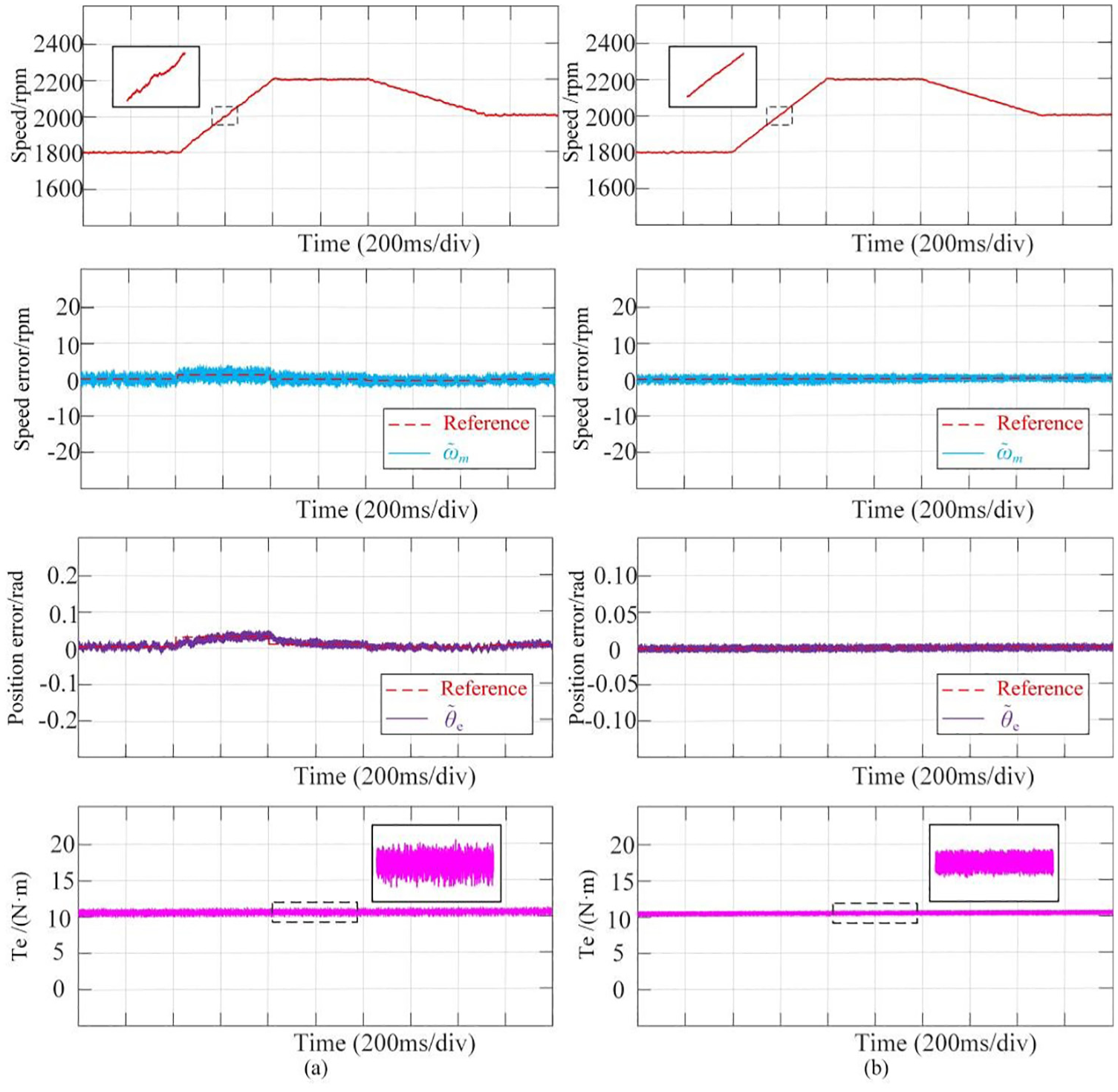
Experimental results under varying load torque conditions: (a) SMO-PLL scheme and (b) proposed scheme.
As shown in the above figure, when the speed changes, the SMO-PLL scheme can achieve speed tracking within a certain error range. However, from the local graph, it can be seen that the tracking effect is poor and there are obvious fluctuations. The proposed scheme can achieve stable tracking and control of the speed throughout the entire process. In terms of speed error, it can be seen that the conventional scheme, as analyzed in Section “Analysis and improvement of PLL,” has a steady-state error in tracking the speed ramp reference signal, with a maximum value of 2 rpm. However, the proposed control scheme estimates the speed through FLL in the feedforward open-loop and compensates errors through PLL in the closed-loop, enabling it to achieve tracking without steady-state error throughout the entire process. The accuracy of speed is also reflected in the position of the rotor. Specifically, the conventional scheme generates a maximum steady-state error of 0.04 rad in rotor position tracking, which affects the effectiveness of control. The proposed scheme can also track the rotor position without steady-state error. In addition, in terms of output torque, due to the introduction of STA, high-frequency chattering is weakened, resulting in a smaller torque ripple.
Summary of experimental results
Theoretical analysis in Section “Analysis and improvement of PLL” and the experiments in this section have substantiated the superiority of the proposed sensorless control scheme in both steady-state and dynamic control effects. Based on the comparison of observers and FLLs respectively and the control effect of speed, position, and current control conditions under other operating conditions in experiment, it can be concluded that the proposed scheme in this paper not only has higher control accuracy compared to conventional schemes, but also better suppresses chattering.
The comparison between the conventional sensorless control scheme based on SMO and PLL and the proposed scheme is presented in Table 2 as follows. The table illustrates that the proposed scheme exhibits enhanced performance compared to the conventional scheme in various aspects, enabling superior control of PMSM.
Performance comparison between two schemes.

Conclusions
An efficient sensorless control system should have the following qualities: high accuracy of observation characteristics, high accuracy of rotor position information acquisition, and a certain degree of robustness. In this paper, regarding these aspects, a new sensorless control scheme based on SMO and FLL is proposed for sensorless control of PMSMs at medium and high speeds. In obtaining rotor information, STA and FCA are combined and promoted to improve the accuracy and parameter flexibility of the observer. In the optimization of signal analysis, DSOGI-FLL is introduced and enhanced. By combining it with a compensatory PLL, a new structure is formed, achieving high-precision tracking of the extended back-EMF and rotor information. The proposed control scheme not only retains the advantages of conventional SMO and PLL structure systems but also optimizes their limitations, achieving higher tracking accuracy.
Both theoretical analysis and experimental results indicate that the proposed sensorless control scheme more accurately obtains rotor information under various operating conditions, better controls PMSM, and enables it to provide a better driving effect.
Footnotes
Handling Editor: Xiaodong Sun
Author contributions
Conceptualization, L.H. and T.Z.; methodology, T.Z.; software, C.C.; validation, L.H., C.C., and T.Z.; formal analysis, L.H.; investigation, C.C.; writing – original draft preparation, L.H.; writing – review and editing, C.C. and T.Z. All authors have read and agreed to the published version of the manuscript.
Declaration of conflicting interests
The author(s) declared no potential conflicts of interest with respect to the research, authorship, and/or publication of this article.
Funding
The author(s) disclosed receipt of the following financial support for the research, authorship, and/or publication of this article: This research was funded by Huaian City Key R&D Plan Projects,grant number HAG202302.
Data availability statement
Data are contained within the article.