
Abstract
When the HV battery of a hybrid electric vehicle encounters severe faults, the 12 V battery can easily become depleted, forcing the vehicle to shut down. To address this issue, this paper proposes a novel voltage control strategy specifically tailored for a 48 V P0 mild hybrid system in a MHEV. The strategy comprises two main components. The first component is a dual closed-loop control strategy with weak magnetic control for the MCU, ensuring a stable voltage output from the BSG in generator mode across a wide speed range. The second component is a hierarchical control-based voltage control strategy for the HCU. In this context, the HCU serves as the central controller, coordinating with the BMS, MCU, DC/DC, and ECU to harmonize the voltage control mode of the hybrid system. The effectiveness of this strategy has been confirmed through bench and vehicle tests. Test results indicate that the strategy enables the hybrid system to maintain acceptable HV bus voltage fluctuations and provides effective hardware protection under various scenarios. The strategy guarantees that the vehicle can continue operating after a severe fault in the 48 V battery, thereby enhancing the robustness of the hybrid electric vehicle system.
Introduction
Globally, major vehicle markets have implemented fuel regulations to curb CO2 emissions and enhance fuel economy across various regions worldwide.1–5 For instance, the European Union has imposed a CO2 emission limit of 95 g/km as an average for a car manufacturer’s fleet since 2020. According to EU regulations, this limit is set to decrease by 15% by 2025 and by 37.5% by 2030. Comparable objectives have been established for CO2 emissions in other countries such as the US (109 g/km in 2025) and China (95 g/km in 2025). As these regulations become increasingly stringent, enhancing fuel economy has emerged as a significant challenge for the automotive industry.6–8 While enhancing the efficiency of internal combustion engines (ICE) can contribute to achieving these targets, it is insufficient without additional measures. 9 Consequently, the development of new powertrain systems with electrification has emerged as a promising solution to boost powertrain efficiency and decrease fuel consumption.10–12 Among these electrification solutions, the 48 V mild hybrid technology is notable due to its cost-effectiveness, simple structure, and significant fuel consumption reduction.13–15
The 48 V hybrid system offers a straightforward configuration that requires minimal modifications to existing powertrains, making it easily adaptable to various vehicle models with minor platform or architecture changes.10,13 In this configuration, the 48 V electric motor assists the ICE in providing propulsion and recovers braking energy to store it in a small 48 V battery with a capacity of approximately 0.3–1 kWh. While the combustion engine remains the main source of propulsion in mild hybrids, the stored energy in the battery can be utilized for additional torque and to power the vehicle’s electrical systems. These combined benefits result in a fuel consumption reduction ranging from 8% to 18%, depending on the specific system topology. 10 Moreover, the 48 V mild hybrid technology significantly enhances the start-stop function and power performance, leading to improved driving quality and an enhanced customer experience. Given these advantages, the 48 V mild hybrid technology has become increasingly attractive to consumers.
In recent years, the 48 V P0 mild hybrid system has gained popularity due to its cost-effectiveness. This system integrates the engine and belt-driven starter generator (BSG) to enable hybrid functions such as start-stop, torque boost, regeneration, and load shift.16,17 The start-stop function allows the engine to shut off when the vehicle is stationary or coasting, reducing idle fuel consumption and emissions. The torque boost function provides additional torque from the BSG when needed, improving acceleration and performance. The regeneration function recovers kinetic energy during braking and converts it into electrical energy stored in the battery, reducing fuel consumption and brake wear. The load shift function adjusts the engine load with the BSG, allowing the engine to operate at the optimal efficiency point. However, if the 48 V battery fails to maintain a high voltage due to severe faults, it can interrupt the normal operation of the 48 V P0 mild hybrid power system. As a result, certain functions of the system may become disabled, including the supply of power to the 12 V power net through the DC/DC converter (DC/DC). In most mild hybrid electric vehicles (MHEVs), where conventional generators are eliminated to reduce costs, the 12 V battery becomes the sole power source for all 12 V loads. Without the support of the DC/DC, the 12 V battery may rapidly deplete, potentially causing the MHEV to shut down. Additionally, in the 48 V P0 hybrid system, the battery also serves as an energy buffer. If the battery is damaged and cannot absorb or release energy properly, and if the BSG operates in TORQUE CONTROL mode, which controls its regenerative torque regardless of its output voltage or current, the bus voltage may exceed the threshold of the DC/DC, potentially triggering overvoltage faults and resulting in damage to the converter. 18
Reliable design is crucial for improving the reliability of high-voltage (HV) battery systems and addressing failure issues. To achieve this goal, three main approaches have been explored in previous research. The first approach focuses on enhancing system design robustness through the application of Failure Mode and Effects Analysis (FMEA) and Fault Tree Analysis (FTA) methods. Held and Brönnimann 19 utilized these methods to design experiments for battery system-level fire accidents. However, experimental testing has limitations as it cannot cover all possible failure scenarios due to the diverse and complex nature of battery failure causes and consequences. Another approach involves battery fault prediction schemes based on various data sources. Chen et al., 20 Finegan and Cooper, 21 and Zhao et al. 22 proposed different methods utilizing artificial neural networks, machine learning, and cloud computing and Internet of Things technologies, respectively, to predict and warn of battery failures. While these methods can improve battery management, safety, and performance, they primarily focus on preventive measures rather than corrective actions. The third approach is the utilization of Dual Hybrid Energy Storage Systems (Dual-HESS). Eckert et al. 23 suggested a novel electric vehicle configuration consisting of two independent HESS, each connected to an electric motor for rear and frontal propulsion. The two driving systems are linked by a power management controller that distributes the power demand among them. This setup allows the electric vehicle to operate with one system if the other is deactivated due to reaching the maximum discharge. However, Dual-HESS increases cost, weight, volume, and complexity, making this solution less favorable for widespread adoption.
After a severe fault in the HV battery, ensuring the vehicle’s normal operation and enabling it to travel to a repair station for maintenance are critical issues for automobile manufacturers. This issue has been studied by only a few researchers so far. For instance, Jing et al. 18 proposed a method for a P2.5 hybrid system that switches the motor to voltage control mode if the battery contactor opens due to a fault. The electric machine then acts as a generator and collaborates with key controllers (battery management system (BMS), vehicle control unit (VCU), motor control unit (MCU), engine control unit (ECU)) to ensure a steady HV output. However, this study only briefly introduces the voltage control strategy process and does not provide a detailed description of the voltage control strategy or the motor control strategy under voltage control mode.
To effectively address the challenge of vehicle shutdown caused by severe HV battery faults, this study proposes a novel voltage control strategy and conducts comprehensive validation using a newly developed MHEV. The possible contributions of this study can be summarized in three aspects: (1) the study introduces a dual closed-loop control strategy with weak magnetic control for the MCU; this strategy ensures stable voltage output from the BSG in generator mode across a wide speed range, providing a solid foundation for the vehicle’s reliable power supply; (2) the study proposes a hierarchical control-based voltage control strategy for the HCU; the HCU coordinates with the BMS, MCU, DC/DC, and ECU to harmonize the voltage control mode of the hybrid system, greatly improving the system’s overall efficiency and responsiveness; and (3) this study conducts bench and vehicle tests to validate the effectiveness of the strategy; the test results indicate that in the event of a severe fault in the 48 V battery, the strategy ensures that the vehicle can continue operating, effectively preventing shutdown issues caused by battery failures.
The rest of this paper is organized as follows: Section “Vehicle and 48 V P0 system configuration” introduces the vehicle and the 48 V P0 system under investigation. Section “BSG power generation control strategy” presents the BSG power generation control strategy. Section “Hybrid system voltage control strategy” details the hybrid system voltage control strategy. Sections “Test methodology” and “Results and discussion” respectively outline the test methodology and comprehensively present the test results. Finally, Section “Conclusion” provides the conclusion and outlines future work.
Vehicle and 48 V P0 system configuration
Vehicle configuration
The subject of this study is a newly developed MPV, equipped with a 2.0 TGDI gasoline engine and a 48 V P0 hybrid system. The general specifications of the vehicle are presented in Table 1.
Main specifications of the vehicle.

48 V P0 system configuration
The 48 V P0 system includes an HCU, a BSG, a DC/DC, a 48 V battery, and related wiring harnesses. All modules of the system are controlled through the CAN bus. An overview of the MHEV architecture is shown in Figure 1.

Overview of MHEV architecture.
The HCU plays a central role as the primary controller of the MHEV hybrid system. It collects vehicle information and operating status from each powertrain subsystem through the CAN network. It further analyzes driver intentions, calculates the torque demand for the engine and BSG, and coordinates the ECU, TCU, MCU, BMS, and DC/DC. 24 This integration of control allows for smooth operation and optimal performance of the hybrid system. Additionally, Energy Management Strategies (EMSs) are embedded within the HCU’s control logic to efficiently distribute power between the engine and BSG. The effectiveness of these EMSs significantly impacts the overall energy consumption of the vehicle. 25
The BSG is a hybrid excitation synchronous motor (HECSM) incorporated into the belt drive system of the combustion engine, which can regulate torque in motoring and generating modes. It can operate as an intelligent generator and starter, regenerate braking energy, charge the 48 V battery, and supply torque to the combustion engine. Five control modes of the BSG—Startup, Normal Operation, Shutdown, Active Discharge, and Voltage Control—are available. Startup mode is activated when the MCU is initiated. Normal Operation takes up most of the vehicle’s driving time, and in this state, the BSG has three modes: Standby, Torque Control, and Speed Control. Shutdown mode is activated when the MCU powers down, while Active Discharge mode is employed under high-priority conditions when the 48 V battery contactor is open to quickly discharge the HV bus. Voltage Control mode maintains the HV bus voltage when the 48 V battery contactor opens due to battery faults. When the 48 V battery fails or loses its charging and discharging functions, the BSG operates in Voltage Control mode as a generator. In this mode, the HCU sends the target bus voltage to the BSG, and the BSG regulates the bus voltage within an acceptable range using PI control.
The DC/DC serves as the interface between the 48 V electrical network and the traditional 12 V electrical network. It enables forward and reverse power conversion modes, ensuring efficient power transfer between the two networks. The 48 V network primarily consists of the BSG and a 48 V battery, while the 12 V network comprises a 12 V battery, a 12 V starter, instrument panels, lights, and other 12 V loads. The DC/DC plays a critical role in maintaining the stability and reliability of the power supply across both networks.
The 48 V battery system contains 12 lithium-ion cells. Its main functions are to store energy and release it when needed. In the event of severe faults, such as the contactor sticking, a cell open circuit, or a link voltage open line, fault information is transmitted to the HCU. Upon receiving this information, the HCU issues a Fault Indicator (FID) to disable the HV system and commands the 48 V battery contactor to open.
The main specifications of 48 V P0 system is shown in Table 2.
Main specifications of 48 V P0 system.

BSG power generation control strategy
To ensure stable voltage output from the BSG during generator mode across a wide speed range, an advanced control strategy is employed and integrated into the MCU. This strategy is based on the mathematical model of BSG motor and focuses on precise regulation of the excitation current.
HECSM mathematical model in d–q coordinate system
The HECSM is a special type of motor that combines the effects of an excitation winding and permanent magnets to generate excitation magnetic flux.26,27 The rotor of this motor has a pair of claw poles that alternate between N and S poles. The excitation winding and permanent magnets are mounted coaxially, forming a parallel magnetic flux structure. The permanent magnets are surface-mounted uniformly in the gaps between adjacent claw poles. The excitation winding is arranged in a ring shape around the claw poles and positioned on the rotating shaft. Both the excitation winding and the permanent magnets share the same set of armature windings. The magnetic flux includes both axial and radial components and interacts with the armature windings through the air gap between the stator and rotor. Compared to traditional permanent magnet synchronous motors, the hybrid-excitation synchronous BSG motor has an additional controllable excitation current, which makes its control strategy and mathematical model more complex. The following passages introduce the mathematical model of the HECSM. For simplicity, magnetic saturation, iron loss, and temperature dependencies are neglected in the model. 28
The mathematical model in the d–q rotating coordinate system is as follows28,29:
Flux equations:

Where,
Stator voltage equation:

Where,
Electromagnetic torque equation:

Where,
Equation (3) shows that the output torque of the motor consists of three components. The first term is the permanent magnet torque, which is generated by the interaction between the permanent magnet flux and the armature current. The second term is the reluctance torque, which arises from the difference between the d-axis and q-axis inductances due to the saliency effect of the rotor. The third term is the electric excitation torque, which is produced by the interaction between the stator current and the electric excitation flux.
The BSG motor used in this study has a surface-mounted permanent magnet structure and employs a vector control strategy with
BSG power generation control strategy
This section presents the power generation control strategy for the BSG system based on vector control principles. The overall framework of the power generation control strategy is shown in Figure 2, which consists of the following modules: BSG, coordinate transformation module, PI controllers, SVPWM, three-phase inverter, excitation current drive module, single-phase inverter, and current reference allocation.28,29

Overall power generation control strategy diagram of the BSG system.
In power generation mode, the engine drives the BSG to produce a three-phase AC voltage. This voltage is then converted by an inverter to charge a 48 V battery or power electrical loads.
The power generation control strategy adopts a dual closed-loop vector control structure that consists of an inner current loop and an outer voltage loop. This motor uses the
To ensure the normal operation of a three-phase inverter, it is essential to meet the specific limiting conditions stated in equation (4) for voltage and current.30,31 These conditions must be carefully followed during the power generation process.27,29,31

Where,
Once the desired voltage reference value (
Hybrid system voltage control strategy
To ensure the normal operation of the hybrid vehicle even after a severe fault occurs in the 48 V battery, a voltage control strategy has been integrated into the HCU control software. This strategy relies on real-time monitoring of the 48 V battery’s state by the BMS. When a severe fault is detected, the BMS notifies the HCU, which commands the MCU to transition from its current mode to Voltage Control mode. This mode serves as a specialized power generation state for the MCU. In this mode, the MCU dynamically adjusts the BSG output voltage to keep it within a reasonable range, preventing potential vehicle damage due to excessively high or low bus voltage levels. During the voltage control process, the HCU acts as the central controller, seamlessly collaborating with the BMS, MCU, DC/DC, and ECU to harmonize the VOLTAGE CONTROL mode within the hybrid system. Here, the term VOLTAGE CONTROL mode denotes a specific operational state of the hybrid system.
The strategy of enabling and disabling VOLTAGE CONTROL mode
Figure 3 presents the conditions for enabling and disabling VOLTAGE CONTROL mode. To enable VOLTAGE CONTROL mode, the following seven conditions must be met simultaneously:

Conditions for enabling and disabling VOLTAGE CONTROL mode.
Firstly, the HV system’s power supply status must be Initial or HV disable. After the vehicle powers on, the HV system initially enters the Initial state. If a severe fault occurs in the 48 V battery during this phase, the status remains Initial. Conversely, during normal driving, a severe 48 V battery fault will cause the HCU to disable the HV system, changing the status to HV disable.
Secondly, the 48 V battery contactor must be open. In the event of a severe 48 V battery fault, the HCU commands the 48 V battery contactor to open, and the BMS also opens the contactor.
Thirdly, the BSG must be in Neutral or Auto Diag mode. Initially, the motor enters Auto Diag mode after vehicle power-on. It transitions to normal operation only after successful auto-diagnosis, which relies on BMS signals (e.g. battery voltage). If the BSG does not receive BMS signals for auto-diagnosis, it remains in Auto Diag, preventing hybrid system operation. To address this, BSG in Auto Diag is included in the voltage control enabling conditions. Additionally, during normal driving, if a severe fault occurs in the 48 V battery, the HCU commands the BSG to enter Neutral mode.
Fourthly, the engine must have run for at least 10 s (adjustable) to ensure stable operation, which enables it to power the BSG for electricity generation upon entering VOLTAGE CONTROL mode.
Fifthly, the 12 V battery voltage must exceed 9 V (adjustable) to ensure sufficient power for pre-charging the capacitors on the 48 V power net and powering the 12 V loads before entering VOLTAGE CONTROL mode.
Sixthly, no faults should inhibit the voltage control function.
Finally, the failure counter for entering VOLTAGE CONTROL mode must be less than 3. This counter tracks consecutive unsuccessful attempts within the current driving cycle, increments each time VOLTAGE CONTROL mode is enabled, and resets to zero upon successful entry. It also resets automatically at the start of each driving cycle. Figure 4 shows the calculation logic for this counter.

Calculation logic for the failure counter for entering VOLTAGE CONTROL mode.
These seven conditions are all necessary for enabling VOLTAGE CONTROL mode. When the 48 V battery encounters a severe fault, the hybrid system responds with a series of actions. The first three conditions (1, 2, and 3) are typically satisfied under normal conditions. Conditions 4 and 5 ensure the hybrid system operates normally in VOLTAGE CONTROL mode. Condition 6 ensures no other faults inhibit the mode and supports conditions 1, 2, and 3. Condition 7 prevents repeated unsuccessful attempts to enter VOLTAGE CONTROL mode. This strategy ensures accurate assessment of the hybrid system’s status and swift activation of VOLTAGE CONTROL mode.
As soon as VOLTAGE CONTROL mode is enabled, the engine’s target idle speed is increased to 1100 rpm to enhance idle stability. At the same time, the engine’s maximum speed is limited to 3500 rpm. This means that the BSG’s maximum speed is restricted to 9380 rpm (considering the speed ratio between the BSG and engine is 2.68). The purpose of this limitation is to prevent the BSG motor from entering a high-speed range where voltage stability is typically poor.
To ensure the safety of the hybrid system, the HCU will determine whether to disable VOLTAGE CONTROL mode based on the engine state, HV system’s power supply status, BSG state, voltage control state machine, and fault information, as shown in Figure 3. If any of these conditions are met, VOLTAGE CONTROL mode will be disabled. Notably, the HCU will closely monitor the BSG state in VOLTAGE CONTROL mode. If the BSG enters Out-of-Range (OOR) mode and remains in this state for a certain (adjustable) period, the HCU will disable VOLTAGE CONTROL mode. This is because OOR mode is a safety protection mechanism of the BSG. When the BSG speed or output voltage exceeds the predetermined operating range, the MCU will consider the BSG’s operating condition to be abnormal or unsafe and automatically trigger OOR mode, causing the BSG to cease electricity generation.
The strategy of entering VOLTAGE CONTROL mode
Figure 5 shows the seven steps (from step 0 to step 6) of the voltage control state machine, which controls the process of entering and exiting VOLTAGE CONTROL mode. This process requires the HCU to coordinate the BMS, MCU, DC/DC, and ECU in a predetermined sequence. Step 0 means that the hybrid system is in the non-VOLTAGE CONTROL mode. When VOLTAGE CONTROL mode is enabled, the state machine initiates the process of entering VOLTAGE CONTROL mode and moves from step 1 to step 5 in order. If the HCU detects a timeout during this process, the state machine transitions to step 6. Step 5 signifies that the system has successfully entered VOLTAGE CONTROL mode. When VOLTAGE CONTROL mode is disabled, the state machine initiates the process of exiting VOLTAGE CONTROL mode and returns to step 0.
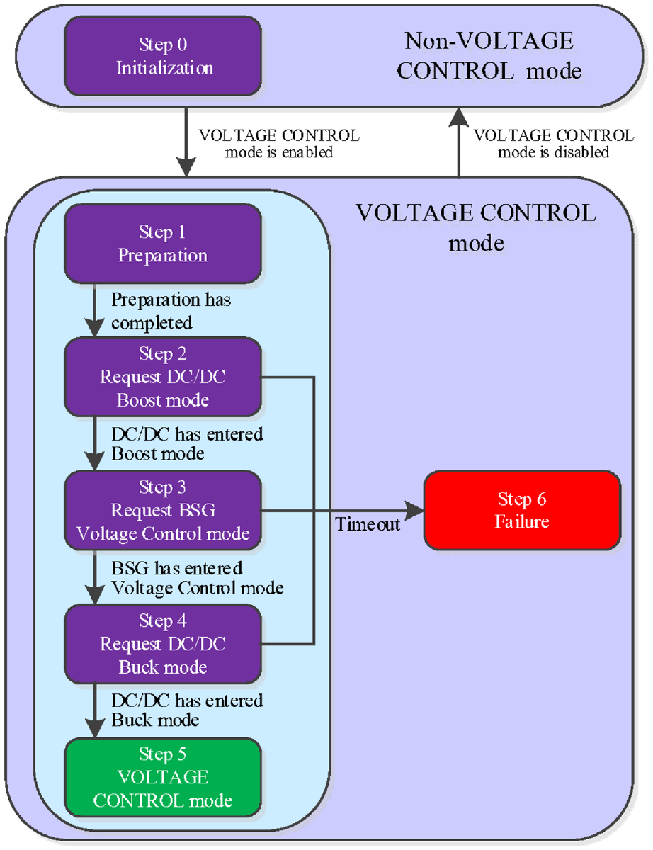
Voltage control state machine.
Figure 6 illustrates how the system enters and exits VOLTAGE CONTROL mode.

Process of entering and exiting VOLTAGE CONTROL mode.
Step 1: Preparation
When VOLTAGE CONTROL mode is enabled, the voltage control state machine transitions from step 0 to step 1, initiating the process of entering VOLTAGE CONTROL mode. In step 1, the HCU requests all controllers to cease operations in preparation for subsequent steps. Specifically, the HCU directs the DC/DC to enter Standby mode, the MCU to enter Neutral mode, and the BMS to open the 48 V battery contactor. For safety reasons, the 48 V battery contactor must remain open throughout the entire process of entering and exiting VOLTAGE CONTROL mode.
To transition from steps 1 to 2, the hybrid system must satisfy two conditions simultaneously. The first condition is that the BSG terminal voltage must remain below 37 V for 3 s. The second condition is that the engine speed must be within the predetermined range. Figure 7 illustrates the transition conditions from steps 1 to 2. In this study, the predetermined minimum and maximum engine speeds are set to 1000 and 3600 rpm, respectively, with a hysteresis of 50 rpm.
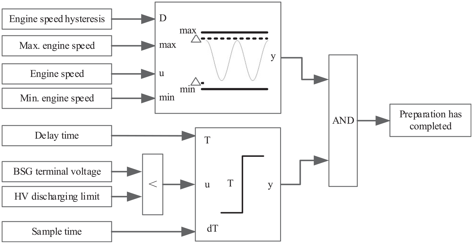
Transition conditions of the state machine from step 1 to step 2.
Since the bus voltage rapidly drops below 37 V after the 48 V battery contactor is opened, the first condition is easily met. Once VOLTAGE CONTROL mode is enabled, the idle target speed is set to 1100 rpm, enabling the engine speed to quickly enter the predetermined range. However, in some special operating conditions, such as long downhill runs, the second condition may not be met for an extended period. If timeout protection were set in step 1, the state machine could switch to step 6, increasing the fault count and preventing entry into VOLTAGE CONTROL mode. Therefore, this study did not implement timeout protection in step 1.
Step 2: Request DC/DC Boost mode
To prevent excessive current between the BSG and the HV capacitor when the BSG enters Voltage Control mode, which could damage the HV components, a pre-charging process was designed. When the state machine transitions to step 2, the HCU requests the DC/DC to enter Boost mode with a boost voltage of 39 V and a maximum boost power limited to 500 W. Figure 8 shows the state machine transition conditions from steps 2 to 3. When the BSG terminal voltage exceeds 38 V for more than 3 s, the HCU assumes that the DC/DC has entered Boost mode, and the voltage control state machine transitions to step 3.

Transition conditions of the state machine from step 2 to step 3.
In the case where the duration of step 2 exceeds 10 s, it is identified as a timeout, and the state machine transitions to step 6 while simultaneously incrementing the failure counter for entering VOLTAGE CONTROL mode by one. Furthermore, during this step, the MCU remains in Neutral mode.
Step 3: Request BSG Voltage Control mode
In this step, the HCU instructs the BSG to enter Voltage Control mode with a target voltage of 40 V, which is typically set 1 V higher than the boost voltage of the DC/DC. During this step, the DC/DC remains in Boost mode to ensure voltage stability. Experimental results indicate that if the DC/DC transitions to Standby mode at this point, it may lead to significant fluctuations in the 48 V side voltage until the BSG enters Voltage Control mode.
When the voltage control state machine stays in step 3 for more than 50 ms and the BSG enters Voltage Control mode, the HCU assumes that the BSG has entered Voltage Control mode, and the state machine transitions to step 4. Figure 9 illustrates the transition conditions from step 3 to step 4. However, if the BSG fails to enter Voltage Control mode within 10 s, it results in a timeout, prompting the state machine to transition to step 6 while also incrementing the failure counter for entering VOLTAGE CONTROL mode by one.

Transition conditions of the state machine from step 3 to step 4.
Step 4: Request DC/DC Buck mode
To distinguish between Buck operation in VOLTAGE CONTROL mode and Buck in non-VOLTAGE CONTROL mode, a new type named Buck_Voltage Control has been added to the enumeration for the requested DC/DC mode. The DC/DC buck voltage value and buck current limit differ between these two requested modes. However, the actual mode of the DC/DC for both requests remains the same, that is, both are Buck.
When the HCU instructs the DC/DC to enter Buck_Voltage Control mode, the buck voltage is set to 13.7 V. However, if the 12 V load suddenly increases, it may cause the 48 V side voltage to drop. To ensure system stability, the DC/DC current gradient on the 48 V side is restricted to 200 A/s.
After successfully entering Buck mode, the voltage control state machine transitions to step 5. If the DC/DC fails to enter Buck mode within 10 s, it results in a timeout and the state machine transitions to step 6 while incrementing the failure counter for entering VOLTAGE CONTROL mode by one.
Step 5: VOLTAGE CONTROL mode
If the state machine transitions to step 5, it indicates that the hybrid system has successfully entered VOLTAGE CONTROL mode. In this step, the MCU operates in Voltage Control mode, while the DC/DC remains in Buck mode. The failure counter is reset to zero. The BSG can achieve an output voltage in the range of 24–54 V by employing dual closed-loop control. In this study, the maximum generating capacity of the BSG is set at 2.2 kW.
Step 6: Voltage control failure
If a timeout occurs during steps 2, 3, or 4, the system transitions to step 6 and the failure counter for entering VOLTAGE CONTROL mode increases by one. Subsequently, the state machine transitions to step 0 and reassesses the enabling conditions for VOLTAGE CONTROL mode.
The strategy of exiting VOLTAGE CONTROL mode
When VOLTAGE CONTROL mode is disabled, the state machine transitions to step 0 and the system initiates the process of exiting this mode. The HCU instructs the BSG to enter the Neutral mode immediately. Once the BSG confirms that it has entered Neutral mode and remains in that state for a minimum of 20 ms, or if the HV bus voltage falls below 25 V, the HCU instructs the DC/DC to enter either the Shutdown or Standby mode, depending on whether the vehicle is powered off. This sequence of actions effectively prevents the bus voltage from surpassing its limit. Experimental data confirms that if the DC/DC enters Shutdown or Standby mode before the BSG enters Neutral mode, a potentially dangerous overvoltage will occur on the 48 V side.
The strategy of calculating the DC/DC voltage and current
When the DC/DC is requested in Buck_Voltage Control mode, the voltage setpoint is a constant value and is calibrated as 13.7 V in this paper. Figure 10 illustrates the DC/DC voltage setpoint calculation strategy.

DC/DC voltage setpoint calculation strategy.
The current limit of the DC/DC depends on its mode and parameters. In Boost mode, the current limit is constrained by the DC/DC maximum power and the minimum voltage on the LV side, which are set to 500 W and 14 V in this paper. In Buck_Voltage Control mode, the current limit is determined by dividing the maximum power of the DC/DC by the voltage setpoint. The control logic for calculating this voltage setpoint is illustrated in Figure 10, and Figure 11 provides a flowchart that outlines the DC/DC current limit calculation strategy.

DC/DC current limit calculation strategy.
Test methodology
Based on the descriptions provided in the preceding chapters, fluctuations in motor speed (which has a fixed proportional relationship with engine speed) and variations in the 12 V load are the two main challenges for maintaining the stability of the HV bus voltage in VOLTAGE CONTROL mode.
When the motor speed changes, the excitation current needs to be adjusted synchronously. During this process, the output voltage of the BSG fluctuates, affecting the stability of the bus voltage.
The sudden activation or deactivation of 12 V loads like air conditioner, headlights, and entertainment systems, which are controlled by the driver, can instantly alter the DC/DC LV side current, significantly impacting the stability of the HV bus voltage. It’s important to note that the key factor influencing voltage stability is the variations in the 12 V load, not its absolute value.
Additionally, there are two significant 12 V loads on the vehicle that are not directly controlled by the driver: the radiator fan (maximum input power 550 W) and the engine’s electronic water pump (maximum input power 490 W). Although the driver cannot directly control these loads, their power consumption can be indirectly influenced by adjusting the vehicle speed, engine speed, and engine load.
In designing the test methodology, the author critically considered scenarios that cover most real-world driving conditions, particularly focusing on speed fluctuations and variations in 12 V loads. The study aimed to thoroughly evaluate the effectiveness of the voltage control strategy through a combination of bench testing and vehicle testing, ensuring stable performance under various driving conditions.
Bench test
The bench test was designed to verify the basic functions of the voltage control system and obtain initial control parameters under steady-state conditions. The test results will help improve the control strategy and optimize future calibration. As shown in Figure 12, the schematic diagram of the bench test illustrates that the upper machine acts as the HCU to coordinate the BSG and DC/DC. The dynamometer simulates the engine and delivers torque to the BSG via the belt, which allows the BSG speed to vary between 2000 and 14,000 rpm. This corresponds to an engine speed of approximately 750–5200 rpm, covering the engine speed range under VOLTAGE CONTROL mode. The 12 V electronic load simulator replaces the 12 V loads in the vehicle and can be adjusted within a current range of 30–300 A, corresponding to a power range of 0.4–4 kW. Actual test data shows that the total maximum power of all 12 V loads on this MHEV does not exceed 2.5 kW, with a corresponding peak current not exceeding 190 A. This ensures that the simulator can cover the required range of 12 V load power. The BSG, DC/DC, and 12 V battery are identical to those in the actual vehicle. Since this test needs to simulate a 48 V battery failure scenario, the bench test does not include a 48 V battery.

Schematic diagram of the bench test.
The bench test was conducted in three groups. In the first group, the speed of the BSG was fixed while adjusting the 12 V electronic load. Specifically, the motor speed was set to 2500, 5000, 7500, and 10,000 rpm sequentially, with the electronic load varying between 30 and 190 A at each speed.
In the second group, the 12 V electronic load was fixed, and the dynamometer speed was varied. Specifically, the 12 V load was set to 30, 70, 110, 150, and 190 A sequentially, with the motor speed varying between 2500 and 10,000 rpm under each load condition.
The third group was more flexible, with both the dynamometer speed and the 12 V electronic load being randomly adjusted. The motor speed varied between 2500 and 10,000 rpm, while the 12 V load was randomly adjusted within the range of 30–190 A.
Vehicle test
The vehicle test aimed to verify the full functionality of the voltage control strategy after the hybrid system had matured. To achieve this, the newly developed MPV, a 48 V P0 mild hybrid electric vehicle, was used. Various test cases were designed to simulate practical application scenarios. To improve the test efficiency, this paper simulated abnormal battery states by using software control methods to force the battery contactor open.
The vehicle test consisted of two groups of tests: static and dynamic.
The static tests were conducted while the vehicle was stationary to examine the coordination between various controllers, including the HCU, BSG, DC/DC, BMS, and ECU, when entering and exiting VOLTAGE CONTROL mode. Four static tests were designed to simulate different scenarios. The first test simulated the 48 V battery contactor being open before the engine started. The second test simulated a 48 V battery fault causing the 48 V battery contactor to disconnect during normal driving. The third test simulated powering off the vehicle while in VOLTAGE CONTROL mode. The fourth test simulated the BSG or DC/DC entering FAILURE mode while the vehicle was in VOLTAGE CONTROL mode. These four tests cover all scenarios for entering and exiting the VOLTAGE CONTROL mode.
The dynamic tests aimed to assess the full functionality of the VOLTAGE CONTROL mode in practical driving scenarios, including its performance under engine speed fluctuations and 12 V load variations in various operating conditions, as well as its fault detection and protection mechanisms.
The author chose the Guangde Proving Ground in Anhui, China, to conduct the dynamic tests due to its excellent testing facilities and comprehensive test procedures and scenarios. These procedures and scenarios, designed based on global advanced testing protocols and refined over more than a decade, ensure a high degree of scientific rigor and representativeness. The author selected 10 test items from the comprehensive durability test set, which were divided into two categories:
Typical application scenarios: Seven tests were chosen to represent typical driving scenarios encountered by customers. These included urban standards, high-speed standards, straight track standards, high-speed cruise, Belgian road cycles, handling test loops, and slalom standards.
Extreme conditions: Three tests with dramatic changes in vehicle speed, engine speed, and engine load were selected to represent extreme conditions for the VOLTAGE CONTROL mode. These included maximum speed tests, high-speed braking standards, and emergency braking.
Thus, these 10 tests covered both typical driving scenarios and extreme conditions, enabling a comprehensive evaluation of the voltage control strategy under the majority of real-world driving scenarios.
In actual driving, the driver does not operate all 12 V loads simultaneously. Therefore, in the vehicle dynamic test, the performance of the VOLTAGE CONTROL mode was evaluated by simulating sudden changes in high-power loads, such as the air conditioner, which can cause a current surge of up to 45 A when switched on.
Since the VOLTAGE CONTROL mode is a temporary working mode under fault conditions, designed to help the driver safely reach a repair point, some adjustments were made to certain tests, such as limiting the speed to no more than 175 kph in the maximum speed test and repeatedly accelerating and decelerating to verify the impact of significant changes in speed and load on the performance of the VOLTAGE CONTROL mode. Additionally, the driver randomly switched the air conditioner on and off while ensuring safety.
Evaluation criteria for test results
When the hybrid system transitions from normal mode to VOLTAGE CONTROL mode, or the opposite, or when it operates in VOLTAGE CONTROL mode, the output voltage of the BSG should be kept within a range of 24–54 V. This measure is implemented to safeguard the DC/DC from potential harm.
If the 48 V battery fails, the hybrid system can quickly transition to VOLTAGE CONTROL mode to prevent the depletion of the 12 V battery.
Moreover, if the hybrid system experiences other faults or if the output voltage of the BSG surpasses its safety limit, the system can quickly exit from VOLTAGE CONTROL mode. This prompt action helps prevent potential damage to the hybrid system’s hardware.
Results and discussion
Bench test
The bench test is the preliminary step in the software development process that aims to identify software control strategy issues and acquire critical control parameters promptly. Once the software has matured, a comprehensive vehicle test is conducted that covers the test items as the bench test. The bench test results can be reflected in the vehicle test results, and therefore, this paper will not present them alone.
Vehicle test
Static test
Test case 1: The 48 V battery contactor is open before engine start
This test simulates a scenario when the 48 V battery contactor has been disconnected before the engine starts. Due to the disconnection of the 48 V battery contactor, when the driver presses the start button, the HCU determines that engine startup by the BSG is not permitted and initiates startup using the 12 V starter. At 1074.1 s, the engine startup was successful.
After running for 10 s, at 1084.1 s, the HCU determined that all conditions for entering VOLTAGE CONTROL mode were met. Consequently, the state machine transitioned to step 1, and the engine’s target idle speed was set to 1100 rpm, resulting in an increase in engine speed. At 1086.3 s, when the engine speed reached 1050 rpm, the preparation step was completed, and the state machine transitioned to step 2. In step 2, the HCU requested the DC/DC to enter Boost mode and set the target voltage value to 39 V for pre-charge. At 1089.5 s, the HV bus voltage had risen above 38 V for 3 s, and the state machine transitioned to step 3. In step 3, the HCU requested the BSG to enter Voltage Control mode with a target generating voltage of 40 V. At 1089.6 s, the system had been in step 3 for over 50 ms, and the BSG had provided feedback in Voltage Control mode; therefore, the state machine transitioned to step 4. In step 4, the HCU requested the DC/DC to enter Buck_Voltage Control mode. At 1089.7 s, the DC/DC had provided feedback in Buck mode, and the state machine transitioned to step 5, which indicated that the system was officially in VOLTAGE CONTROL mode. The total duration of this process (from step 1 to step 5) was 5.6 s in this test case. Figure 13 shows the results of test case 1.

Results of test case 1.
Test case 2: The 48 V battery contactor disconnects during normal driving
This test simulates the scenario when a 48 V battery fault causes the 48 V battery contactor to open during normal driving.
At 2148.55 s, the HCU received the fault information and subsequently issued the Fault Indicator (FID) to disable the HV system and the command to open the 48 V battery contactor. The BMS’s feedback at 2148.60 s confirmed that the 48 V battery contactor was open. Following this, the HCU instructed the DC/DC to enter Standby mode, which was confirmed by the DC/DC feedback at 2148.63 s. After a 150 ms delay from the FID, the HCU commanded the BSG to enter Neutral mode at 2148.70 s. The BSG’s feedback at 2148.72 s confirmed it was in Neutral mode, indicating that all conditions for entering VOLTAGE CONTROL mode were met. Therefore, VOLTAGE CONTROL mode was enabled at 2148.73 s. After 10 ms, the voltage control state machine transitioned to step 1, indicating the start of the process to enter VOLTAGE CONTROL mode, which was identical to test case 1. The total duration of this process (from step 1 to step 5) was 8.6 s in this test case. Figure 14 shows the results of test case 2.

Results of test case 2.
Test case 3: The VOLTAGE CONTROL mode is disabled when the vehicle is powered off
This test simulates the scenario of powering off the vehicle while in VOLTAGE CONTROL mode. The vehicle was powered off at 1064.385 s, which disabled VOLTAGE CONTROL mode at 1064.395 s. The voltage control state machine then transitioned to step 0 at 1064.405 s. The HCU requested the BSG to enter Neutral mode and received confirmation from the BSG after 40 ms. Next, the HCU commanded the DC/DC to enter Shutdown mode, and the DC/DC feedback confirmed this action at 1064.491 s. The total duration of this process (from the state machine transitioning to step 0 to the point where the DC/DC feedback indicates entry into Shutdown mode) was 86 ms in this test case. The BSG and DC/DC stayed in their current state until further instructions were given by their controllers. Figure 15 shows the results of test case 3.

Results of test case 3.
Test case 4: The VOLTAGE CONTROL mode is disabled when the BSG or DC/DC enters FAILURE mode
This test simulates the scenario of the BSG or DC/DC entering FAILURE mode while the vehicle is in VOLTAGE CONTROL mode. The BSG entered OOR mode at 610.17 s due to low HV bus voltage. After a 0.5 s delay, the BSG would exit Voltage Control mode according to the calibration of this study. However, at 610.45 s, the HV bus voltage triggered an undervoltage fault on the DC/DC HV side, causing it to enter FAILURE mode. The HCU received this fault information and issued the FID of inhibiting the voltage control function at 610.53 s, which induced VOLTAGE CONTROL mode to be disabled at 610.54 s. Subsequently, the HCU requested that the BSG enter Neutral mode. At this time, the HV bus voltage had fallen below 25 V, so the HCU requested the DC/DC to enter Standby mode at the same time. After receiving the status of the BSG and DC/DC, the HCU cancelled the FID of inhibiting the voltage control function at 610.68 s and then initiated the process of entering VOLTAGE CONTROL mode again. The total duration of this process (from the state machine transitioning to step 0 to the point where the DC/DC feedback indicates entry into Standby mode) was 52 ms in this test case. Figure 16 shows the results of test case 4.

Results of test case 4.
The static test results show that the proposed strategy ensures the hybrid system swiftly transitions to VOLTAGE CONTROL mode upon detecting severe battery faults. Once in VOLTAGE CONTROL mode, the hybrid system can safely exit the mode when a fault is identified, thus effectively protecting the hybrid system hardware.
Dynamic test
This paper presents the results of four tests selected as examples from a group of 10 dynamic test items.
Test case 1: Urban standards test
Figure 17 shows the partial results of the urban standards test. In this test, the maximum speed was 50 kph, and the average speed was approximately 14 kph, typical of urban driving conditions and commonly encountered by customers. At 25 s, the engine started. At 38 s, the 48 V battery contactor was disconnected, initiating the process of entering VOLTAGE CONTROL mode. By 42 s, the system officially entered VOLTAGE CONTROL mode. Throughout the test, the air conditioner was turned off.

Partial results of the urban standards test.
The current at the DC/DC LV side ranged from 33 to 94 A due to variations in vehicle speed, engine speed, engine load, and engine coolant temperature. The HV bus voltage fluctuated between 36 and 43 V. These voltage levels not only complied with the specifications for VOLTAGE CONTROL mode but also ensured a safety buffer for stability.
Test case 2: High-speed standards test
Figure 18 shows the partial results of the high-speed standards test. In this test, the maximum speed was 130 kph, and the average speed was approximately 88 kph, representing a typical high-speed driving cycle. Before the test began, the engine started and idled while the vehicle was stationary. At 382 s, the 48 V battery contactor was disconnected, initiating the process of entering VOLTAGE CONTROL mode. By 389 s, the system officially entered VOLTAGE CONTROL mode, and the high-speed standards test commenced. Between 695 and 1107 s, the driver repeatedly turned the air conditioner on and off, causing a significant increase in current at the DC/DC LV side.

Partial results of the high-speed standards test.
Throughout the test, the DC/DC LV side current ranged from 28 to 119 A. The HV end voltage fluctuated between 30 and 44 V, demonstrating a sufficient safety margin within the permissible range of the BSG output voltage. The test concluded at 1702 s with the vehicle being powered off and VOLTAGE CONTROL mode exiting normally.
Test case 3: Maximum speed test
Figure 19 shows the partial results of the maximum speed test. During this test, the vehicle’s speed was restricted to 175 kph, with the driver performing aggressive acceleration and deceleration. The purpose was to assess the performance of the VOLTAGE CONTROL mode under rapidly varying speed and load conditions. Throughout the test, the air conditioner was turned off.

Partial results of the maximum speed test.
Before the test began, the vehicle was stationary, and the engine idled as it transitioned into VOLTAGE CONTROL mode. Between 77 and 243 s, the driver gradually accelerated, reaching approximately 175 kph. Subsequently, between 243 and 560 s, the driver continued with aggressive acceleration and deceleration maneuvers, but the vehicle speed remained within the range of 135–175 kph. During this phase, the average vehicle speed was approximately 156 kph, representing an extreme high-speed driving scenario.
Throughout the test, the DC/DC LV side current varied between 29 and 126 A, while the HV bus voltage fluctuated from 32 to 44 V. These voltage levels remained very stable, demonstrating a sufficient safety margin from the permissible range of the BSG output voltage, even in an extreme high-speed driving scenario with aggressive driving maneuvers.
Test case 4: High-speed braking standards test
Figure 20 shows the partial results of the high-speed braking standards test. During this test, the vehicle performed an emergency braking maneuver when its speed reached 135 kph, resulting in rapid decreases in vehicle speed, engine speed, and engine load. The purpose of this test was to assess the performance of the VOLTAGE CONTROL mode under extreme conditions.
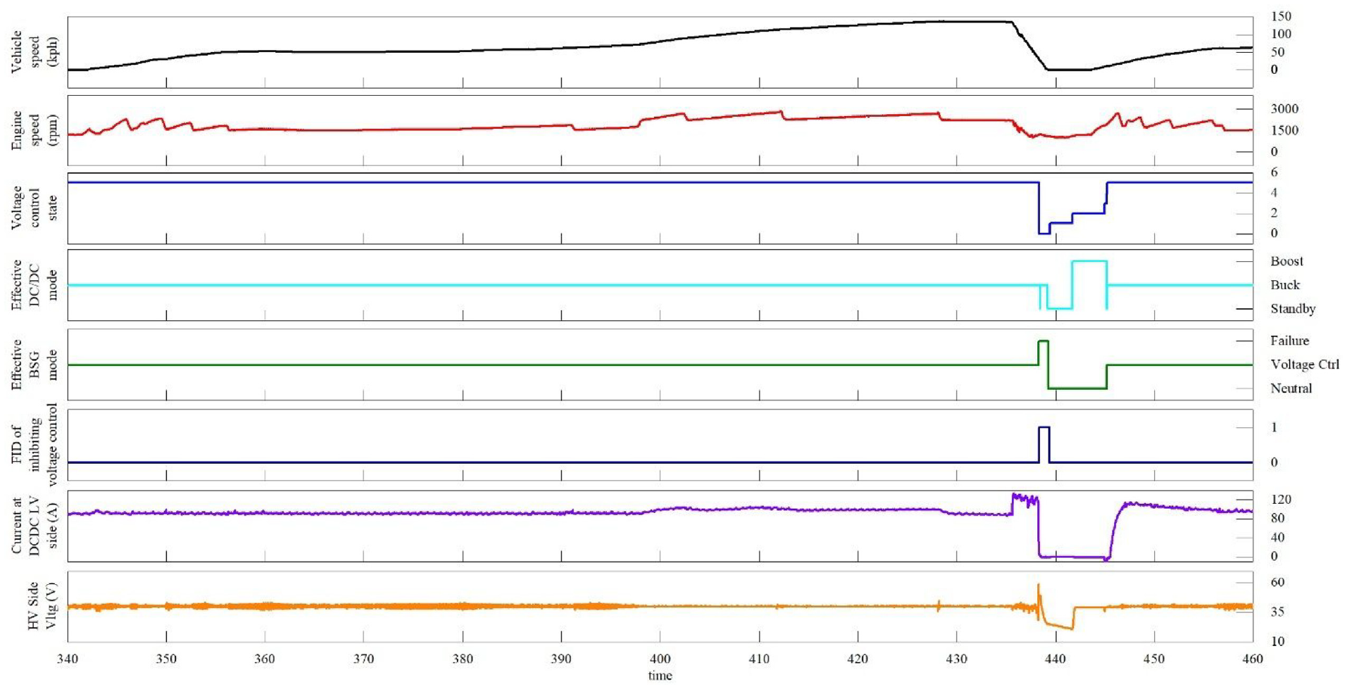
Partial results of the high-speed braking standards test.
Before the test began, the vehicle was stationary, and the engine idled while the system entered VOLTAGE CONTROL mode. At 342.0 s, the vehicle accelerated and reached a constant speed of 135 kph by 426.5 s. Braking commenced at 435.7 s, bringing the vehicle to a stop within 3.4 s. Throughout the test, the air conditioner was turned on.
During the acceleration phase, the engine speed peaked at 2893 rpm, within the allowable range for the VOLTAGE CONTROL mode. The LV side current of the DC/DC remained relatively stable, fluctuating between 88 and 105 A without significant changes. The HV bus voltage fluctuated between 35 and 44 V, staying within the permissible range.
During rapid deceleration phase, the LV side current of the DC/DC spiked from 89 to 131 A within 0.17 s. Simultaneously, the BSG motor speed underwent rapid changes, causing the BSG output voltage to become unstable. Specifically, at 438.27 s, the voltage surged to 58.8 V, triggering the BSG to enter FAILURE mode, which resulted in a subsequent drop in the BSG output voltage. In response, the HCU issued the FID to inhibit the voltage control function at 438.36 s, and VOLTAGE CONTROL mode was disabled at 438.37 s. Ten milliseconds later, the voltage control state machine transitioned to step 0, indicating the start of exiting VOLTAGE CONTROL mode.
After exiting VOLTAGE CONTROL mode, the BSG’s fault was resolved, and it entered Neutral mode. The system detected that VOLTAGE CONTROL mode was re-enabled at 439.41 s and then initiated the process of entering VOLTAGE CONTROL mode.
The dynamic test results demonstrate that the proposed voltage control strategy maintains acceptable HV bus voltage fluctuations under typical driving scenarios, such as urban standards test and high-speed standards test. Notably, even in an extreme high-speed driving scenario with aggressive driving maneuvers, such as a maximum speed test, the voltage remains stable. In more extreme conditions, such as high-speed braking standards test, the system promptly exits VOLTAGE CONTROL mode upon detecting a hybrid system fault and seamlessly re-enters once the fault is resolved.
Conclusion
This paper presents and validates a novel voltage control strategy tailored for a 48 V P0 MHEV vehicle equipped with a HECSM. Static vehicle tests demonstrated that the strategy ensures the hybrid system swiftly transitions to VOLTAGE CONTROL mode upon detecting severe battery faults and safely exits the mode when a fault is identified. Dynamic tests showed that the strategy can maintain acceptable HV bus voltage fluctuations under typical driving scenarios. In extreme conditions, the system can promptly exit VOLTAGE CONTROL mode upon detecting a hybrid system fault and seamlessly re-enter once the fault is resolved. These findings demonstrate that the strategy not only effectively protects the system hardware but also enhances the robustness of the hybrid electric vehicle system.
Future research will focus on two key areas: first, a comparative study assessing the technical advancements of the proposed voltage control strategy in relation to state-of-the-art technologies; second, an adaptability study examining the effectiveness of the strategy in adapting to uncertainties, disruptions, and environmental factors, such as aging and extreme cold conditions. Depending on the findings, adjustments to the control strategy’s parameters and algorithms may be necessary to achieve optimal performance.
Footnotes
Abbreviation
AC Alternating current
BMS Battery management system
BSG Belt driven starter generator
CAN Controller area network
DC Direct current
DC/DC DC/DC converter
ECU Engine control unit
EMSs Energy management strategies
FID Fault indicator
FMEA Failure mode and effect analysis
FTA Fault tree analysis
HCU Hybrid control unit
HECSM Hybrid excitation synchronous motor
HESS Hybrid energy storage system
HV High voltage
ICE Internal combustion engine
LV Low voltage
MCU Motor control unit
MHEV Mild hybrid electric vehicle
MPV Multi-purpose vehicle
OOR Out of range
PI Proportion integration
SVPWM Space vector pulse width modulation
TCU Transmission control unit
TGDI Turbo gasoline direct injection
Author contributions
Ming Shang: Conceptualization, Investigation, Writing – original draft. Zhendong Zhang: Methodology, Writing – review & editing. Congbo Yin: Control strategy design, Experimental investigation
Declaration of conflicting interests
The author(s) declared no potential conflicts of interest with respect to the research, authorship, and/or publication of this article.
Funding
The author(s) disclosed receipt of the following financial support for the research, authorship, and/or publication of this article: The authors thank Lifeng Zhang, Yingxia Feng, and Kai Li (Commercial Vehicle Technology Center of SAIC MOTOR, PR China) for their kind advices and help on this paper.