
Abstract
This paper presents a fuel consumption reduction control strategy for a newly-developed 48 V P0 mild hybrid electric vehicle and evaluates its fuel economy benefit experimentally. The strategy is designed with rule-based methods and utilizes various functions such as start-stop, torque boost, regeneration, load shift, BSG neutral mode and torque interventions with BSG. Fuel consumption comparison tests are performed in the WLTP cycle between the MHEV and the conventional vehicle. The authors evaluate the performance of specific key functions, analyze the energy flow of the 48 V battery, and calculate the fuel saving rate of the MHEV. The SOC of the 48 V battery is balanced in the WLTP cycle. The total energy charged to the 48 V battery is 378 Wh, of which 82% comes from the regeneration pattern. The total energy discharged from the 48 V battery is 355 Wh, of which 85% is consumed by the load shift pattern (BSG neutral state and Discharging state). The fuel consumption of the MHEV is reduced by 7.9% compared with the conventional vehicle in the WLTP cycle. The start-stop, BSG neutral, and torque interventions with BSG save fuel by 3.8%, 0.9%, and 0.5% respectively. The other hybrid functions save fuel by 2.7%.
Introduction
Nowadays, ever higher pressure is coming from the government and the public to reduce vehicle exhaust emissions. Improving the fuel economy and mitigating CO2 emissions have become the main issues of the automotive industry.1,2 In recent years, China’s automobile industry has developed rapidly, resulting in an increasing number of prominent problems of energy shortage and environmental pollution.3–5 Boosting the development of energy-saving vehicles and new energy vehicles is an important means to effectively alleviate energy and environmental pressure.6–10 At the national level, China has introduced the CAFC scheme to regulate the sales weighted average fuel consumption rate of automakers’ products. The phase V CAFC regulation will be fully implemented by 2025, setting a national fuel consumption rate target at 4.0 L/100 km under NEDC cycle, equivalent to CO2 emission of about 95 g/km 11 .
It will be a challenge to meet CAFC regulations in 2025 only by improving the Internal Combustion Engine (ICE) efficiency. The new powertrain systems with electrification should be developed to increase the powertrain efficiency and reduce fuel consumption.12–14 48 V mild hybrid technology is regarded as an effective short-term electrification solution due to its potential fuel consumption reduction and affordable cost.15–17 48 V MHEV has the ability to achieve fuel consumption benefit close to that of a full HEV through the test driving cycle, and only needs minor modifications on the existing powertrain system, so automobile manufacturers can realize agile and efficient development, avoiding dedicated platforms or architectures.14,18 These advantages make the 48 V mild hybrid technology preferable in the current market place.
According to the e-machines position in the vehicle, the configurations of 48 V mild hybrid powertrain are divided into five types: P0, P1, P2, P3, and P4.14,19 Each of these configurations has unique benefits and disadvantages, which are relevant to 48 V architectures and its combination with gasoline or diesel combustion engines.12,20 P0 is the easiest to integrate, which replaces the existing 12 V generator with 48 V BSG. It can realize most hybrid functions such as BSG start, start-stop, boost, regeneration, load shift, and so on. P0 system today is typically limited to 15 kW because little fuel economy is gained at higher power levels. 21 This research mainly focuses on 48 V P0 mild hybrid technology.
Concerning the fuel economy benefit contributed by the 48 V P0 hybrid system, many previous research studies have been conducted. Jun et al. developed a simulator which employed the equivalent consumption minimization strategy (ECMS) algorithm and evaluated the fuel efficiency of a MHEV system consisting of a belt driven motor. The fuel economy benefit is 11.1% in NEDC cycle compared with the base engine. 22 Abidin et al. created two vehicle modes by using a GT Suite software, with and without Belt-Alternator-Starter (BAS) system, to investigate the BAS system functions for fuel consumption. They found that the BAS system improved overall vehicle fuel consumption by 7.7% in NEDC. 23 Zeng and Zhao presented an optimized energy management strategy of 48 V MHEV to reduce fuel consumption. The fuel consumption was tested by UASE Labcar HIL bed in NEDC cycle. Consequently, the fuel saving of 48 V MHEV can reach 9.24% with Start-Stop function. 24 These three studies did the research in NEDC cycle, and the average fuel benefit contributed by 48 V P0 system was 9.35%. However, one drawback of these studies is that they conducted the research in simulation, which lacks the practical considerations of actual vehicle development.
At present, there are few experimental studies on the fuel economy benefit contributed by the 48 V P0 hybrid system. Oh et al. experimentally studied the fuel consumption improvement of an engine with a 48 V P0 mild hybridization in the WLTP cycle. By combining the effect of “Stop in Motion” and optimized electricity management in the 48 V MHEV, the improvement of fuel efficiency in 48 V P0 MHEV was identified to be 5.5% compared with a conventional 12 V system. 18 Oh also stated that the application of electric supercharging and downspeeding leds to a 4.5% improvement in vehicle fuel efficiency. In this study, the 48 V MHEV electric energy during the WLTP cycle is balanced and the 48 V supercharger consumed about 25% electric energy, so the total fuel consumption benefit contributed by the 48 V P0 system should be above 5.5%. Unfortunately, Oh did not precisely calculated this.
This paper presents a control strategy for a MHEV, which is a new MPV with a 48 V P0 hybrid system, to reduce fuel consumption. The paper tests the fuel economy benefit of the 48 V P0 system, quantifies the energy flow of the HV battery under different conditions and the impact of each function on fuel consumption, and evaluates the performance of specific key functions. The control strategy considers multiple factors, such as fuel economy, drivability, and the hybrid system’s safety and reliability, which are integrated during the vehicle development.
Vehicle, engine and 48 V P0 system
Vehicle configuration
The subject used for this study is a newly-developed MPV, which has two versions with different powertrain configurations. The conventional vehicle version is equipped with one 2.0TGDI gasoline engine. The MHEV version deploys a 48 V P0 system, which combines the gasoline engine of the conventional vehicle with a 48 V belt-driven starter generator. General vehicle specifications of these two vehicle versions are shown in Table 1.
Vehicle specifications.

Engine configuration
On the conventional vehicle, the power source is one 2.0TGDI engine with the maximum power of 155 kW and the maximum torque of 350 Nm. This engine applies Early Intake-Valve-Closing (EIVC) technology which enables miller cycle by the combination with a high compression ratio of 11.5:1. Mainly because of the reduced pumping and improved thermal efficiency, Miller cycle can further reduce the fuel consumption. 25 But one disadvantage of Miller cycle is that combustion performance deteriorates as the effective compression ratio declines. 26 In order to compensate for this disadvantage of Miller cycle, this engine employs two-stage VVL technology on the intake camshaft. At low load, the low valve lift with small wrap angle is used to reduce fuel consumption. At high load, the high valve lift with large wrap angle is used for outstanding performance. The main difference between the conventional vehicle engine and the MHEV engine is the water pump. The conventional vehicle employs a switchable water pump, while the MHEV employs an electric water pump to give the engine greater degrees of freedom in its operation.12,18 Table 2 shows the specifications of these two engines.
Engine specifications.

48 V P0 system
The 48 V P0 system includes an HCU, a BSG, a DCDC, a 48 V battery and related wire harness. All modules of the system are controlled through the CAN bus. The overview of the MHEV architecture is shown in Figure 1.
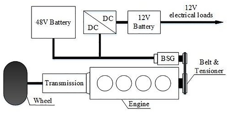
Overview of the MHEV architecture.
HCU is the main controller of the MHEV hybrid system, which is integrated in the ECU. It realizes the coordinated control of the ECU, TCU, MCU, BMS, and DCDC. DCDC connects the 48 V electrical network and the traditional 12 V electrical network and can work in forward conversion and reverse conversion modes. The main components in the 48 V network include the BSG and the 48 V battery; the 12 V network is a traditional low-voltage network, including a 12 V battery, engine starter motor, instrument panel, lights and other low voltage electrical loads. BSG is installed in the belt drive system of the combustion engine. Depending on the operational mode, BSG torque is controlled in both directions (motoring or generating mode). The 48 V battery is a battery system containing 12 lithium-ion cells. The main functions of the battery system are to store the energy, and to feed it back at another point in time. The main specification of the 48 V P0 system is shown in Table 3.
Specification of the 48 V P0 system.

Fuel consumption reduction control strategy
Work modes, torque patterns and load shift states
According to the driver’s driving intention, the vehicle driving state and the vehicle components’ running state, HCU determines the work modes of the 48 V P0 hybrid system, which are described as follows:
Disable mode
When the engine stops, BSG is starting or in fault mode, the system enters this mode.
Conventional charging mode
When the SOC is low, the 48 V battery is overheated, catalyst heating is active, or the vehicle is coasting with low vehicle speed or engine speed, the system enters this mode. In this mode, BSG acts as a conventional generator and charges the 48 V battery.
Hybrid mode
Except for the above conditions, the system enters this mode. In this mode, the engine and BSG respond to the torque command from HCU. BSG provides torque in one of the three patterns, which are torque boost, regeneration, and load shift. In the load shift pattern, there are three states: Charging, Discharging, and BSG Neutral. These patterns and states will be explained in detail below.
Table 4 shows all the work modes, torque patterns, and load shift states in this control strategy.
Work modes, torque patterns and load shift states.

Energy management strategy
Energy management strategy is the core technology of MHEV, which directly affects the fuel consumption of vehicles. 27 In this project, rule-based methods are employed to optimize the energy management, taking fuel economy, drivability, and the hybrid system’s safety and reliability into consideration. The main design principles of the strategy are to keep 48 V battery power balanced and maintain SOC at a reasonable level. In particular, SOC difference before and after the WLTP cycle is limited to 3% to avoid the correction of the CO2 mass emission according to the CN6 emission regulation. 28 SOC level is designed as one of the most important conditions to activate the functions of the 48 V P0 system. To make full use of the system’s functions to reduce fuel consumption, SOC service range of 48 V battery needs to be extended as wide as possible. However, overcharge and deep discharge will shorten 48 V battery lifetime. 15 Therefore, the range should be controlled in a reasonable interval, which is set to 20%−80% in this project. The general view of 48 V P0 energy management strategy is shown in Table 5.
The general view of 48 V P0 energy management strategy.

The whole SOC range is divided into five areas: forced discharging zone, forced charging zone, efficiency optimized discharging zone, efficiency optimized charging zone and neutral zone, as shown in Figure 2. When SOC is higher than 80%, the 48 V P0 system enters the forced discharging zone. In this area, the 48 V P0 system is in hybrid mode but forbids all the functions that charge the battery. When SOC is lower than 20%, the 48 V P0 system enters the forced charging zone. In this area, the 48 V P0 system switches to conventional charging mode to charge the 48 V battery quickly. What’s more, if SOC is lower than 5%, DCDC is forbidden to work to avoid further dropping of SOC. Efficiency optimized discharging zone, efficiency optimized charging zone and neutral zone are combined into the SOC maintenance area. When SOC is between 20% and 80%, the 48 V P0 system enters this area, where the system is in hybrid mode and executes the hybrid function when the corresponding activation conditions are met. The charging and discharging strategy varies according to where SOC is located, and the system performs the required level of charging and discharging to keep SOC at the neutral zone, which is described in detail in the following section.

Charging and discharging strategy.
To extend the discharging depth of the 48 V battery, a dedicated charging and discharging strategy is designed based on the idea that the powertrain’s efficiency can be improved by maximizing the amount of energy recovered during deceleration and coasting phases. Therefore, the strategy aims to discharge the battery as much as possible before entering these phases, so that there is enough energy space to charge the battery by regenerative braking. To achieve this, the target SOC is designed as a function of vehicle speed, as shown in Figure 2. The target SOC decreases with increasing vehicle speed, which means that the system will discharge more energy when the vehicle is at high speed, and charge less energy when the vehicle is at low speed. This way, the efficiency optimized discharging zone extends to the low SOC area at high speed, ensuring that BSG discharges the battery continuously.
Start-stop
Start-stop is a widely used technique to reduce fuel consumption and CO2 emissions, especially in hybrid vehicles.29,30 It allows the engine to stop when the vehicle is either stationary or rolling with the brake applied. These two scenarios are called Static start-stop (SSS) and Rolling start-stop (RSS), respectively. 31 In this project, both types of start-stop have been implemented. However, start-stop may also cause the battery to drain if the electrical load is too high when the engine is off. To prevent this, the energy management system must ensure that the battery has enough energy to restart the engine when needed. In this project, the engine is prevented from stopping automatically when the SOC is below 25%, and is forced to restart when the SOC is below 22%. An accumulator is integrated in the automatic transmission, which enables RSS up to 20 km/h during deceleration. This feature extends the duration of the engine stop in certain driving cycles.
Torque boost
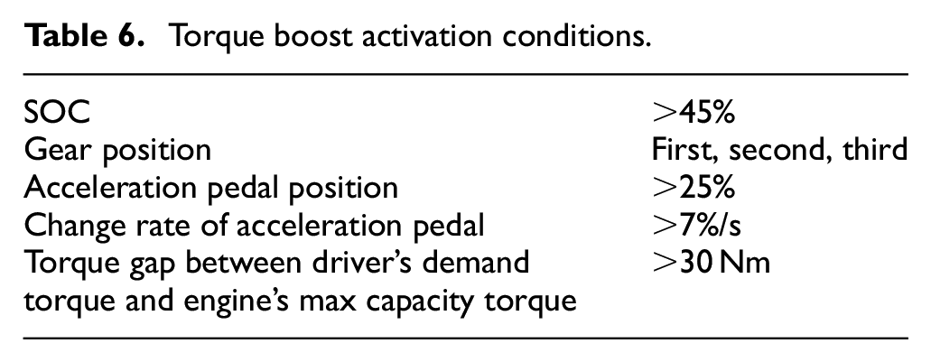
Torque boost is designed to boost the MHEV performance in transient conditions. When the driver has the intention of acceleration and the driver’s demand torque exceeds the max torque of the engine’s current capacity, the torque boost function is activated. BSG consumes the electric energy of 48 V battery to provide additional torque to boost the vehicle. Therefore, in this function, the forward propelling torque is provided by the engine and BSG. In the WLTP cycle, the amount of energy consumed by torque boost is closely related to the driver’s driving style. In an intense driving style, the MHEV will activate the toque boost function frequently and consume more energy than in a moderate driving style. However, the amount of regeneration energy is determined. In the end, the 48 V P0 system has to supplement extra electric energy by raising the engine’s load to guarantee SOC balance. Considering energy conversion loss, it is uneconomical. Therefore, strict activation conditions for the torque boost function are set to reduce such uncertainty. The torque boost activation condition is shown in Table 6.
Torque boost activation conditions.
The schematic diagram of the torque boost calculation model is shown in Figure 3. If SOC is high, it is preferred that more BSG torque is used. On the contrary, if SOC is low, it is preferred that more engine torque is used. Therefore, a factor based on SOC is designed to regulate BSG boost torque, as shown in Figure 4. In the end, the engine requested torque is equal to the driver’s demand torque minus the BSG torque.

Schematic diagram of the boost torque calculation.

Regulated factor of the boost torque based on SOC.
Regeneration
In this project, the regeneration function can be activated when the vehicle is in coasting mode (the driver releases both the acceleration pedal and the brake pedal) or in braking mode (the driver presses the brake pedal). And it can be activated when the transmission input clutch is engaged or in controlled slip mode. The main activation condition of regeneration is shown in Table 7.
Regeneration activation condition.

The process of the regeneration torque calculation is shown in Figure 5. First, the demand drag torque (negative value) at the wheel is determined by two look-up tables, which are designed as the demand drag torque for different clutch states. To protect the transmission, the demand drag torque for clutch controlled slip is set to 72% of the torque for clutch engaged. Then this torque is converted to the torque at the crankshaft side and then regulated by SOC. This regulated factor is mainly to avoid SOC’s further increase in the forced discharging zone. Next, the regulated torque is limited by the transmission allowed torque and is converted to the torque at the BSG side. At last, the torque is limited by the actual power of DCDC (negative value) to ensure that the recuperated energy can cover the consumed energy by the DCDC and the 12 V electrical network.

Schematic diagram of the regeneration torque calculation.
The amount of the recuperated energy is a compromise between fuel economy and drivability. In coasting mode, three aspects have been considered. First, a big drag torque brings a big deceleration, which will harm the customer’s driving experience. The drag torque should be calibrated according to the acceptable drivability. Second, unexpected exit of regeneration should be avoided. Too big drag torque causes the vehicle to be unable to keep up with the desired speed. If the driver has to press the acceleration pedal to speed up, then, regeneration and DFCO exit, which reduces the fuel economy. Therefore, the demand drag torque should be adjusted elaborately to avoid such a case. Third, the transmission clutch will disengage when the vehicle speed declines to about 30 km/h, causing the regeneration torque to disappear suddenly. To avoid the deceleration jump, the demand drag torque is set to a low value near this speed and a smooth ramp is considered. In braking mode, the driver has greater tolerance for big deceleration, so the demand drag torque at the wheel is set according to BSG maximum charge capacity. In addition, similar to in coasting mode, anti-deceleration-jump has been considered. The demand drag torque in coasting mode and in braking mode is shown in Figure 6.

The demand drag torque at wheel level.
Load shift
Compared with the conventional vehicle, the MHEV can provide an additional degree of freedom for regulating the engine running points to achieve fuel savings. In hybrid mode, if neither the activation conditions of torque boost, nor those of regeneration can be met, the system will enter the load shift pattern.
The process of the load shift torque calculation is shown in Figure 7. Three look-up tables, designed as the functions of speed and demand torque, determine the load shift torque. The SOC level decides which table to use. The charging and discharging strategy varies according to where SOC is located, as shown in Figure 2. When SOC is in the neutral zone, the load shift torque is calculated through the look-up table for the neutral zone. In this project, this table is set to 0, that is, neither charging nor discharging by BSG is active. When SOC is located in the efficiency optimized discharging and forced discharging zone, the load shift torque is calculated through the look-up table for high SOC. In the high demand torque area, this table is calibrated as a positive value to shift the engine’s load points to a lower level. The greater the demand torque, the greater the shift torque. While, in the low and middle demand torque areas, the load shift torque is set to 0. When SOC is located in the efficiency optimized charging zone, the load shift torque is calculated through the look-up table for low SOC, which is also calibrated according to the demand torque. In this state, the objective of the control strategy is to maintain or enhance the SOC level. Therefore, the whole table is calibrated as a negative value to ensure charging. The smaller the demand torque, the smaller the absolute value of the shift torque. DCDC work power and BSG efficiency are considered to compensate for the shift torque. As mentioned earlier, when SOC is located in the forced charging zone, the 48 V P0 system switches to the conventional charging mode.

Schematic diagram of the load shift torque calculation.
BSG neutral
The neutral mode is a safe state mode (all MOSFETs are opened) of BSG, which does not allow self-energizing. In this mode, no energy is fed into the intermediate circuit or taken out of it. Therefore, the mode is considered as a passive mode and is used during the waiting phase. BSG efficiency is rather low when the requested torque is small. In the load shift pattern, if the absolute value of the demand torque at the crankshaft level is lower than 2 Nm, BSG switches to the neutral mode to avoid such a low efficiency area.
Torque interventions with BSG
In the process of automatic transmission shifting, TCU will send a torque request to achieve engine speed synchronization. This helps to get smooth and quick shifting. In the project, BSG is designed to respond to the torque increase request from TCU. In the downshift process, TCU will send a torque increase request. As soon as HCU receives the request, it preferentially allocates the required torque to BSG. Only when the required torque exceeds the BSG’s capacity, the excess part is responded to by the engine. The function is often used in coasting down to extend the duration of DFCO. However, to avoid engine stall in extreme cases such as heavy braking, BSG is forbidden to respond to torque reduction requests.
Test vehicles and methodology
Test vehicles
In this study, one MHEV and one conventional vehicle were selected to do the tests, both of them are in the OTS phase. Several ECU function modules of the MHEV have been redesigned or recalibrated due to the addition of the hybrid system, mainly including the torque structure, torque model, start, emission, EWP control, and accelerator pedal map. The TCU calibration data of these two vehicle versions are completely identical.
Test methodology
Fuel consumption comparison tests were conducted in the WLTP cycle with both the MHEV and the conventional vehicle to investigate the fuel consumption benefit of the 48 V P0 system. The same test parameters of the MHEV were applied to both vehicle versions’ tests to directly evaluate the fuel consumption benefit of the 48 V P0 system. After run-in, each test was repeated twice to confirm repeatability.
To better illustrate the impact of driving style on the torque boost function, the authors conducted WLTP tests on the MHEV with two drivers of different driving styles. One driver had an aggressive driving style, while the other had a mild driving style. Both drivers followed the test specifications during the test process, ensuring the validity of the test results. To eliminate other influencing factors of the test, the tests were arranged in the same emission laboratory and conducted on consecutive days.
To evaluate the impact of two hybrid functions, the BSG neutral and the torque interventions with BSG, on fuel consumption, the authors adjusted the calibration data of the MHEV to turn off each function separately. The authors then conducted WLTP cycle tests with each function off and compared the results with those when both functions were on.
Key signals from various controllers of the hybrid system were collected and recorded during the tests, such as vehicle speed, engine torque, engine speed, instantaneous fuel injection rates, HV battery voltage, HV battery current, BSG torque, BSG speed, DCDC power, SOC, hybrid work mode, and torque pattern. The emission data and fuel consumption were also collected and recorded by the emission equipment. These data will be used for subsequent comprehensive data analysis.
Results and discussion
Work mode and torque pattern
The work mode and torque pattern in the WLTP cycle are shown in Figure 8. In the entire WLTP cycle, Disable mode takes 271 s, of which the engine shutdown time is 260 s, and the engine start time is 11 s. Conventional charging mode takes 59 s, during which catalyst heating is 32 s, and the remaining 27 s are attributed to mode entry due to the engine speed being below the threshold. Hybrid mode takes 1470s, with the Torque boost pattern consuming only 5 s, while the Load shift pattern extends for 1276 s. Within the Load shift pattern, BSG neutral state takes 955 s, accounting for 53% of the entire cycle. Figure 9 summarizes the working time and percentage for each work mode, torque pattern and load shift state in the cycle.

Work mode and torque pattern in the WLTP cycle. (1) Work mode: 0 = disable; 1 = conventional charging; 2 = hybrid mode and (2) Torque pattern: 1 = load shift; 2 = torque boost; 3 = regeneration.

Working time for each work mode, torque pattern and load shift state in the WLTP cycle.
SOC balance
The SOC variation during the WLTP cycle is shown in Figure 10. The SOC before and after the WLTP cycle is equal to 49%, which means the SOC is balanced. The SOC service range is 31%–67%. There is enough margin from the forced charging and forced discharging zone, which ensures the hybrid system’s safety and reliability. These suggest that the energy management strategy is effective.

SOC performance in the WLTP cycle.
The dedicated charging and discharging strategy significantly enhances the energy recuperation capabilities of the 48 V P0 mild hybrid system, contributing to improved fuel efficiency and overall performance. In the WLTP cycle, this strategy can produce electric energy efficiently by using regenerative braking and coasting. Notably, during phase 4 of the cycle, when the vehicle undergoes deceleration in band 2 from 131.3 to 0 km/h in approximately 70 s, an increase of 18% in the SOC is achieved through regenerative braking, raising the SOC from 31% to 49%.
The importance of maintaining a proper SOC balance for optimal energy management is highlighted by the need to ensure sufficient energy space for charging in subsequent phases. As demonstrated in band 1, the engine’s operational points are situated within a high fuel consumption region. To address this, the 48 V P0 system employs a load shift function, strategically discharging the battery to shift the engine’s load points to a more fuel-efficient range. To enable continuous discharging during band 1, the target SOC is dynamically adjusted based on vehicle speed, as depicted in Figure 2. This dynamic adjustment extends the efficiency optimized discharging zone to lower SOC levels during high-speed scenarios, facilitating continuous battery discharging through the BSG.
Engine running points
The operating points of the two types of vehicles were clustered using the k-means clustering tool in MATLAB, resulting in 50 cluster centers respectively. Figure 11 displays the cluster centers of the conventional vehicle and the MHEV in the WLTP cycle. The weight of each cluster center is represented by the circle size. As seen in Figure 11, the conventional vehicle has a lot of operating points in the idling area A, because it does not have a start-stop function. However, the MHEV has a start-stop function and, with the help of the RSS function, most of the operating points in area A are shifted to the shutdown condition. Moreover, due to the load shift function, the points in area B with low load and area C with high load are moved to a region between these two areas where BSFC is lower.
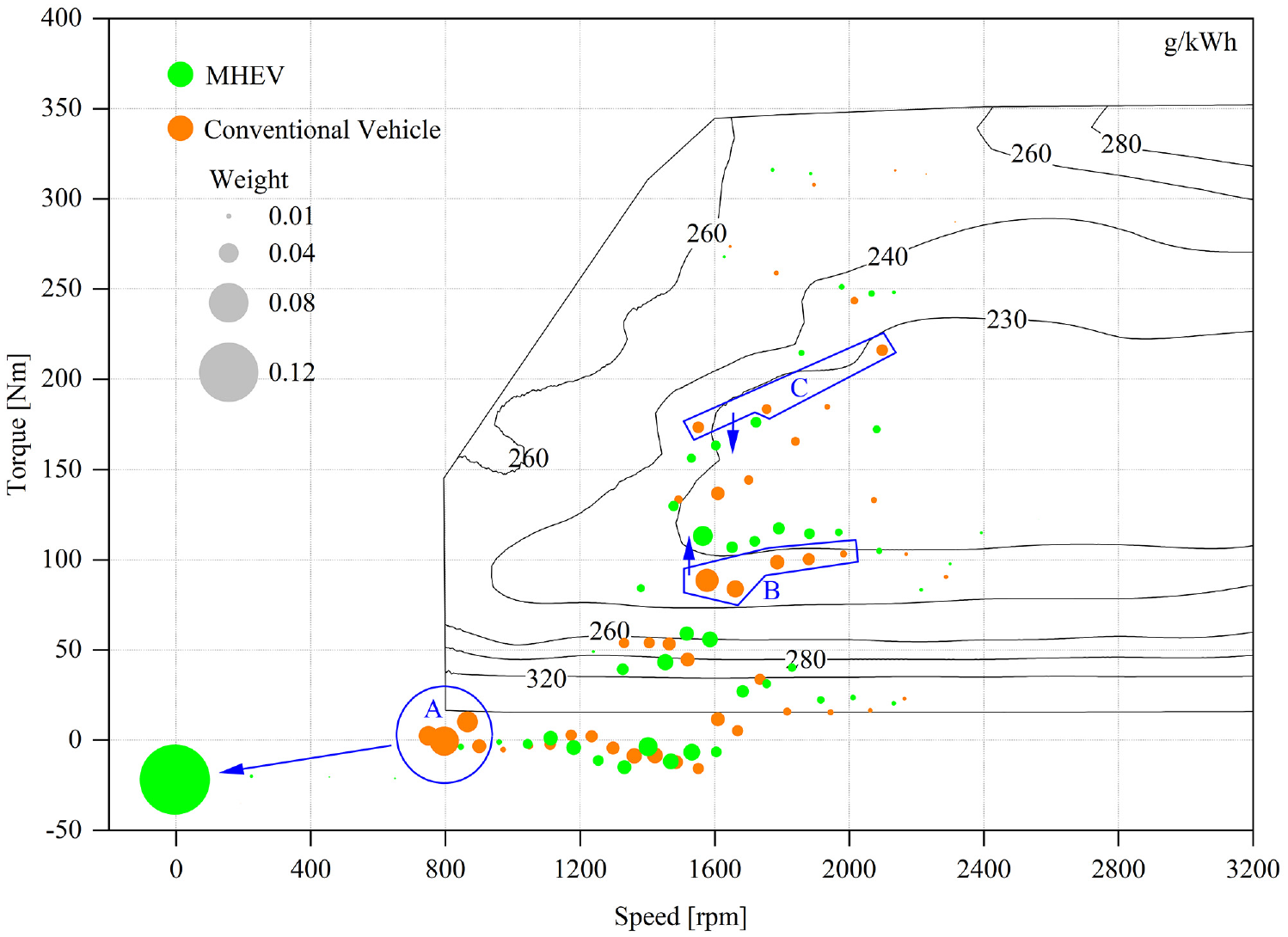
The cluster centers of the engine running points.
Start-stop
One of the challenges of implementing RSS is the delay between the HCU sending a stop order to the engine and the engine executing the order. This delay is caused by communication and computation time, and it affects the timing and duration of engine stop. In this project, HCU sends a stop order when the vehicle speed declines to 20 km/h. However, due to the delay, the engine executes the order after about 1 s. Therefore, the engine usually enters stop mode when the vehicle speed declines to about 16 km/h.
According to a test conducted in the WLTP cycle, RSS can effectively reduce fuel consumption by increasing the engine off time. The WLTP cycle has eight sections where the vehicle stops, with a total duration of 226 s. With RSS, the total duration of engine stop in these sections is extended to 260 s, which is an increase of 15%. The performance of start-stop in the WLTP cycle is shown in Figure 12.
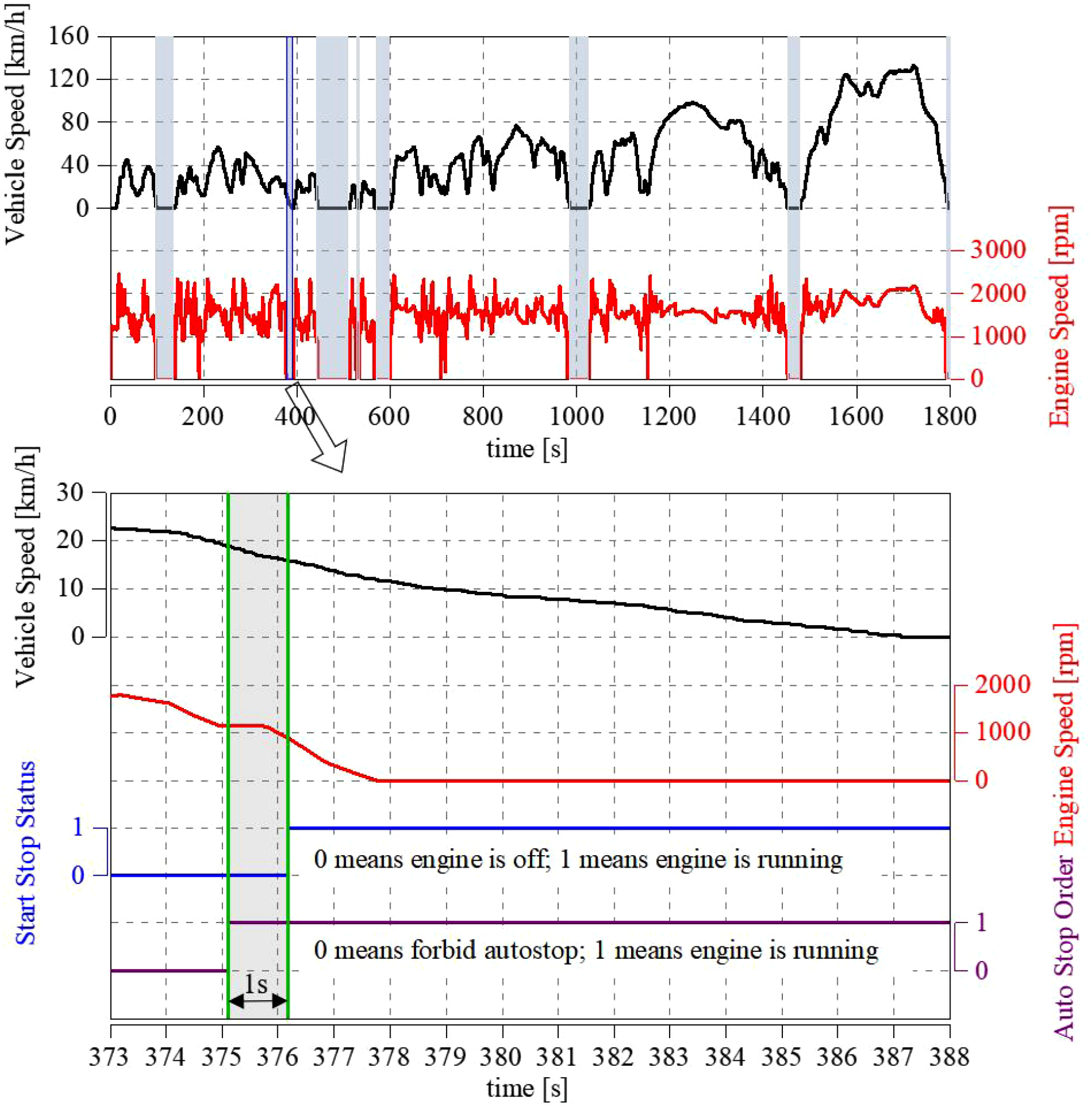
The performance of start-stop in the WLTP cycle.
Torque interventions with BSG
Figure 13 shows the torque interventions with BSG in phase 4 of the WLTP cycle. During coasting, the vehicle speed and gear decrease. In downshifting, BSG responds to the torque increase request from TCU, and the engine stays in DFCO mode throughout. This avoids repeated engine start-ups, extending the DFCO duration and saving fuel.

Torque interventions with BSG in the WLTP cycle.
The influence of driving style on the torque boost
The authors compared the WLTP test data of two drivers with different driving styles. A segment of data from phase 3 of the WLTP cycle was extracted to analyze how driving style affects the torque boost, as shown in Figure 14. In regions 1 and 2, the vehicle speed is increasing, and the aggressive driver presses the accelerator faster and deeper. This can be clearly seen from the accelerator pedal change rate and maximum opening. Accordingly, the aggressive driver’s demand torque is also larger, resulting in a torque gap greater than 30 Nm. This triggers the torque boost function, where the boost function was triggered twice in region 1 and once in region 2. On the other hand, the mild driver only triggered the torque boost function at the first half of region 1 due to the torque gap exceeding the threshold.

The influence of driving style on the torque boost. (1) The solid line depicts test data for aggressive driving style, and the dotted line represents test data for mild driving style.
The electric energy consumption of the boost function in regions 1 and 2 was calculated by the authors using the voltage and current values of the BSG. The power consumed by the BSG in boost function was obtained by multiplying these values, and then integrated over time to get the electrical energy consumption. The energy consumption of torque boost is closely related to the driving style of the driver. In the region shown in Figure 14, the aggressive driving style consumed 10.1 Wh of energy, while the mild driving style consumed only 5.5 Wh of energy.
The energy flow of the HV battery
The author calculates the real-time power of the HV battery by multiplying the current and voltage, and integrates the power over time under various working modes, torque patterns, and load shift states to obtain the electrical energy. Figure 15 shows the energy flow of the HV battery.
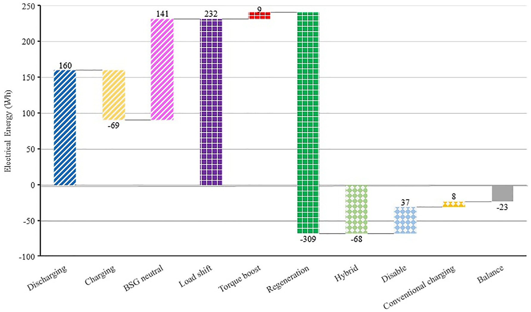
The energy flow of the HV battery. (1) Positive value indicates 48 V battery discharges; Negative value indicates 48 V battery charges.
In the whole WLTP cycle, Disable mode consumes 37 Wh of electrical energy, which is mainly consumed by the DCDC and the 12 V electrical network during engine shutdown, and consumed by BSG during startup. Conventional charging mode consumes 8Wh. The design intention of this mode is mainly to ensure that the hybrid system can generate electricity as a conventional engine. To make the BSG torque change smoothly, after entering this mode, the BSG torque rises from 0 Nm to the target in 2.5 s. However, although the system enters this mode 26 times, the duration it remains in this mode generally does not exceed 2 s. Within such a short period, the electrical energy generated by BSG has not exceeded the consumption of the DCDC and the 12 V electrical network, and the insufficient part is provided by the 48 V battery.
Hybrid Mode charges 68 Wh. In Hybrid mode, Regeneration pattern charges 309 Wh, which is basically fixed with the proposed control strategy. Torque boost pattern only consumes 9 Wh (3%), which meets the design objective of the control strategy. Load shift mode consumes 232 Wh. In Load shift mode, BSG neutral state takes a very long time (955 s) and 141 Wh is consumed, all of which is consumed by the DCDC and the 12 V electrical network. Discharging state consumes 160 Wh. Charging state charges 69 Wh to balance SOC.
The electrical energy consumed in Torque boost pattern and Discharging state is mainly used for engine torque increase. By reducing energy consumption in this pattern and state, it becomes possible to lower the electrical energy generated in the Charging state while maintaining SOC balance. Thus, decreasing energy consumption during Torque boost pattern and Discharging state can lead to improved fuel efficiency. However, such a reduction might sacrifice vehicle performance and impact the driving experience, necessitating a comprehensive consideration of these factors.
The 48 V battery has a total charged energy of 378 Wh, of which 82% comes from the regeneration pattern. It also has a total discharged energy of 355 Wh, of which 85% is consumed by the load shift pattern (BSG neutral state and Discharging state). The difference between the charged and discharged energy is 23 Wh, which is mainly due to the energy loss in charging and discharging the battery. Additionally, the DCDC and the 12 V electrical network consumed a total electrical energy of 266 Wh, which accounts for 75% of the total discharging energy.
Fuel consumption reduction and each function’s contribution
Table 8 shows the results of the fuel consumption comparison tests. Taking the conventional vehicle as the baseline, the overall fuel consumption of the MHEV has reduced 7.9% in the WLTP cycle. The fuel consumption benefit is at a reasonable level compared with the previous research,15,16 which proves the effectiveness of the control strategy.
Fuel consumption test results.

In the WLTP cycle, Disable mode encompasses both engine start and engine stop-start conditions. To assess the fuel-saving effect of the start-stop functionality in MHEV, the difference in fuel consumption under Disable mode is calculated by excluding the first start, as illustrated in equation (1):

In this equation,
The calculation of
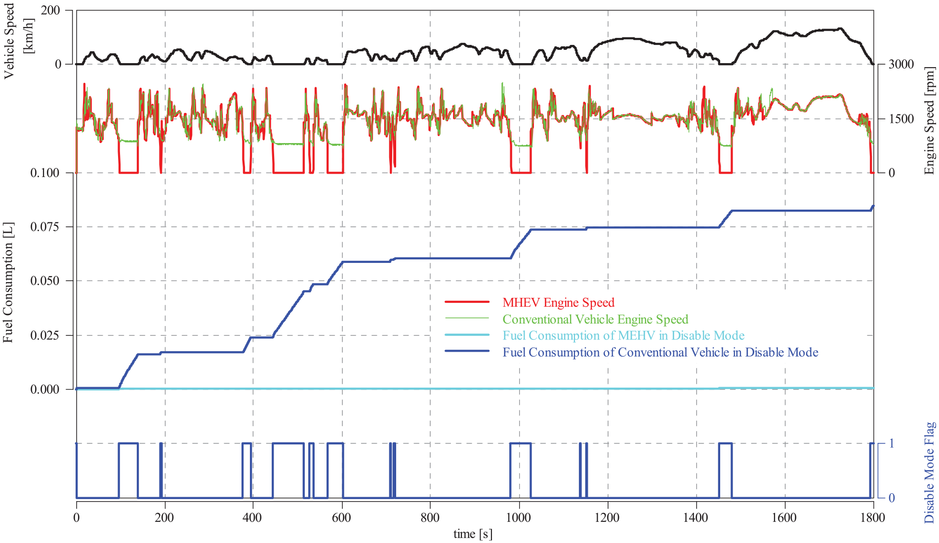
The fuel consumption volume of MEHV and conventional vehicle in disable mode.
In accordance with the principle of energy conservation, an equation for quantifying the gasoline volume produced from HV battery electric energy is deduced as follows:

In this equation,
For the sake of calculation simplicity, reasonable average or typical values are assumed for the parameters in equation (2) within this specific case calculation. These include
To determine the raw fuel consumption benefits of both the BSG neutral function and the torque interventions with BSG function, we compared the test results with each function turned off against the result when both functions were active. However, the tests conducted with each function turned off showed variations in the SOC at the test’s beginning and end, introducing potential inaccuracies in assessing the fuel consumption benefits. To rectify this, the authors calculated the SOC difference between the test’s start and finish, then multiplied this difference by the energy capacity of the HV battery (350 Wh). This calculation yielded the battery energy variance. Subsequently, the battery energy variance was incorporated into equation (2) to compute the corrected fuel quantity. Notably, it’s essential to emphasize that the parameters employed in equation (2) for this case differ from those utilized in the start-stop function scenario. Ultimately, we combined the corrected fuel quantity with the raw fuel consumption benefits to determine the ultimate fuel consumption benefits. Finally, the fuel-saving contributions resulting from BSG neutral and torque interventions with BSG were 0.081 and 0.043 L/100 km, respectively.
Due to the intricate interactions and interconnections among other hybrid functions like Regeneration, Torque boost, and Load shift, isolating the individual fuel-saving contributions of these functions becomes highly challenging. Therefore, this study refrained from further dissecting the fuel-saving effects of these functions.
In conclusion, the fuel savings achieved by the Start-stop function, BSG neutral function, and torque interventions with BSG function were 3.8%, 0.9%, and 0.5%, respectively. The remaining hybrid functions contributed to a fuel consumption reduction of 2.7%. The fuel consumption benefits of each function are graphically represented in Figure 17.

Fuel consumption benefit of each function.
Conclusion
This paper presents a rule-based control strategy for reducing the fuel consumption of a 48 V P0 MHEV. The strategy utilizes various functions such as start-stop, torque boost, regeneration, load shift, BSG neutral, and torque interventions with BSG. Fuel consumption comparison tests are performed in the WLTP cycle between the MHEV and the conventional vehicle, which adopt the same test parameters as the MHEV. The main findings of this study are:
The SOC is balanced and stays within a safe margin from the forced charging and discharging zones in the WLTP cycle, ensuring the safety and reliability of the 48 V P0 system.
The RSS function eliminates the idling zone of the conventional vehicle by switching to the engine-off condition. The load shift function shifts a large number of low-load and high-load operating points to a lower BSFC direction.
The total energy charged to the 48 V battery is 378 Wh, of which 82% comes from the regeneration pattern. The total energy discharged from the 48 V battery is 355 Wh, of which 85% is consumed by the load shift pattern (BSG neutral state and Discharging state). The total electrical energy consumed by the DCDC and the 12 V electrical network is 266 Wh, which accounts for 75% of the total discharging energy.
The fuel consumption of the MHEV is reduced by 7.9% compared with the conventional vehicle in the WLTP cycle. The start-stop, BSG neutral and torque interventions with BSG modes save fuel by 3.8%, 0.9%, and 0.5% respectively. The other hybrid functions save fuel by 2.7%.
Footnotes
Appendix
Acknowledgements
The authors would also like to acknowledge the support from Commercial Vehicle Technology Center of SAIC MOTOR, PR China.
Handling Editor: Chenhui Liang
Authorship contribution statement
Ming Shang: Conceptualization, Experimental investigation, Writing – original draft. Zhendong Zhang: Methodology, Writing – review & editing. Congbo Yin: Methodology, Writing – review & editing. Kai Li: Control strategy design, Experimental investigation.
Declaration of conflicting interests
The author(s) declared no potential conflicts of interest with respect to the research, authorship, and/or publication of this article.
Funding
The author(s) disclosed receipt of the following financial support for the research, authorship, and/or publication of this article: The research was supported by: Basic Research Project of the Science and Technology Commission of Shanghai Municipality (grant no. 21010503000).