
Abstract
The rising popularity of cycling underscores the need for enhanced safety, particularly under challenging braking conditions. This study introduces a novel high-power switch valve designed explicitly for Bicycle Hydraulic Disc Brakes (BHDBs), incorporating Hydraulic Anti-lock Braking Systems (ABS). Comprehensive Finite Element Analysis (FEA) modeling and subsequent optimization of an existing solenoid valve’s internal geometry were performed through 2D and 3D simulations to evaluate magnetic flux. The improved design achieved a maximum output force of 280 N with a linear stroke of approximately 3.5 mm. Notably, the enhanced system exhibited a 28% reduction in required current, from 5.0 to 3.6 A, a result validated through LabVIEW-equipped custom tests, which stress the credibility of the research. This study underscores significant advancements in high-power switch valves for BHDBs, promising enhanced braking efficiency and safety in high-performance, battery-powered bicycles. These findings not only promise enhanced safety for cyclists but also suggest the potential for broader application in energy-efficient and sustainable bicycle ABS technology, contributing to improved cyclist safety without compromising the environmental and health benefits of cycling. The potential impact of this research extends beyond the immediate context, offering insights that could be applied to other areas of technology and safety.
Introduction
The popularity of cycling is on the rise, as it serves as both a practical mode of transportation and an enjoyable recreational activity. Bicycles have long been recognized as an environmentally friendly and healthy mode of transportation. However, the safety of cyclists has been a growing concern, particularly when braking under challenging conditions.1–5 Traditional bicycle braking systems can lead to skidding, which may result in accidents and injuries. This study is driven by the urgent need for enhanced safety in cycling, particularly under challenging braking conditions. Incorporating anti-lock brake systems (ABS) in bicycles has emerged as a promising solution to address these safety issues, such as preventing wheel lock-up and maintaining control during hard braking.6–8 Anti-lock braking Systems originated in the automotive industry, with the first patent filed by Gabriel Voisin in 1929. Since then, ABS technology has significantly advanced, becoming a standard feature in modern automobiles. 9 The primary goal of ABS is to prevent wheel lock-up and skidding during emergency braking, enabling the driver to maintain steering control and reduce the risk of accidents. 10 The successful adaptation of ABS in bicycles has been a subject of ongoing research, considering bicycle operation’s unique dynamics and constraints. 11 While the principles of ABS are well-established in the automotive context, adapting this technology to bicycles presents distinctive challenges. 12 Bicycles are lightweight, and their braking systems operate on a smaller scale than automobiles. Moreover, energy efficiency is a critical consideration, given the human-powered nature of bicycles. The challenge lies in developing ABS systems that enhance safety without compromising the energy-efficient and sustainable aspects that make bicycles an attractive mode of transportation. 13
Solenoid actuators have gained prominence in ABS systems for their ability to modulate brake pressure with precision and speed. 14 Solenoid actuators offer a compact and efficient solution to control braking forces and prevent wheel lock-up in the context of bicycles. Their electromagnetic mechanism allows for rapid response times, making them well-suited for bicycle operations’ dynamic and lightweight nature. Finite Element Analysis (FEA) is a powerful tool for simulating solenoid actuators’ structural, thermal, and electromagnetic characteristics. By utilizing FEA techniques, researchers can gain valuable insights into the performance of these actuators under various conditions, facilitating iterative design refinement for optimal efficiency and reliability. Performance simulation plays a crucial role in evaluating the overall efficiency of ABS systems. Researchers can assess the real-world impact of the designed solenoid actuators by considering energy consumption, braking response time, and stability. 15 Performance simulation provides a comprehensive understanding of how the ABS systems will function in diverse conditions, guiding further refinements for optimal performance. 16
The response time characteristics of solenoids play a critical role in the performance and safety of Anti-lock Braking Systems (ABS) in modern vehicles. 17 This research investigates the static and dynamic response times of ABS solenoids, crucial parameters influencing the system’s ability to regulate brake pressure effectively during varying driving conditions. 18 Static response time, typically between 10 and 20 ms, dictates how quickly the solenoid stabilizes its position after activation, ensuring precise control over brake pressure modulation. Meanwhile, dynamic response time, often under 10 ms, determines the solenoid’s ability to swiftly respond to control signals, essential for preventing wheel lockup and maintaining vehicle stability during braking maneuvers.19,20
There are many brakes, the most common of which are the C-clamp and V-clamp. These clamps are found on most economy-priced bikes. 10 However, this study uses a slightly more advanced form of brake involving discs (Disks). In this system, pressure to the disc is applied to utilize magnetic attraction generated by the excitation of a solenoid valve. The system pushes a plunger into the solenoid valve, closing an oil circuit and resulting in a hydraulic cylinder pressing the disc. The process achieves the braking effect, but the rapid response characteristics of these disc systems mean that the solenoid valve can also be fired quickly and repeated the same way a car ABS functions. When designing such a system for a bicycle, several factors require consideration:
The construction of the solenoid valve is relatively simple; however, the magnetic force calculation requires consideration.
Magnetic attraction is highly nonlinear. Therefore, the governing equation is complex to estimate.
Where safety is concerned, it is only possible or wise to estimate the material properties of a solenoid valve by prototyping and testing a device.
The leakage flux and flux of the related materials are also challenging to estimate.
Estimating the solenoid valve’s static and dynamic responses is also challenging.
In addition, the evolution of ABS technology for bicycles, the challenges unique to bicycle ABS implementation, the role of solenoid actuators, and the application of Finite Element Analysis and performance simulation collectively form the background for the proposed research. By synthesizing knowledge from diverse sources, this research aims to contribute to the advancement of energy-efficient and sustainable Anti-Lock Braking Systems for bicycles, enhancing their safety without compromising their inherent benefits.
Working principle of solenoid actuator for braking system
The working principle of a solenoid actuator in a braking system revolves around converting electrical energy into mechanical force through electromagnetic induction. When an electric current passes through the solenoid coil, it generates a magnetic field, causing the plunger or armature within the solenoid to move. This linear movement is harnessed to control crucial aspects of the braking system, such as regulating brake fluid pressure or manipulating mechanical linkages. Solenoid actuators are integral in modern braking technologies, contributing to functions like anti-lock braking systems (ABS), which play a pivotal role in rapidly modulating brake pressure to prevent wheel lock-up during sudden and intense braking maneuvers.
Principles of solenoid valves
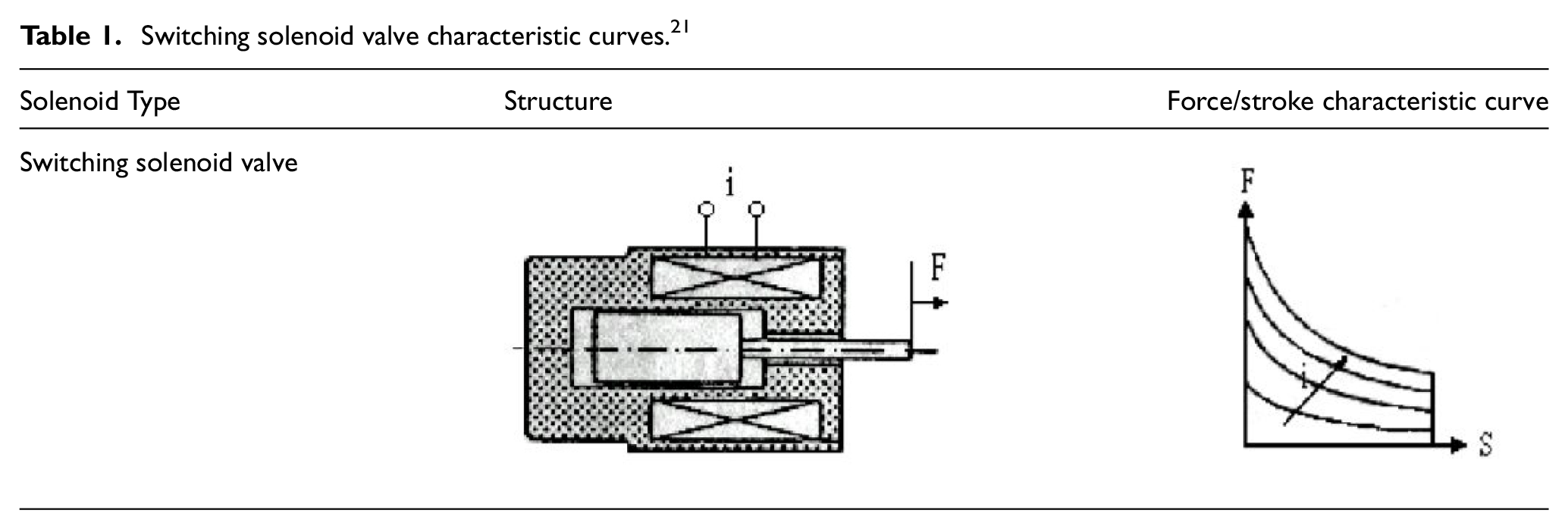
Electro-mechanical transducers (EMTs) are ubiquitous in hydraulic systems and are essential to a complete hydraulic circuit. According to, 21 the core function of an EMT is to utilize magnetic energy generated after the energization of an electromagnetic coil to magnetize the iron core (poppet), thereby opening or closing the valve through associated magnetic forces. Although known for their high response speed, solenoid valves exhibit relatively low output forces. To overcome this limitation, they are frequently incorporated into electro-hydraulic systems, which combine the high response speed of solenoid valves with increased output force.
Construction and analysis of a magnetic circuit for a solenoid valve usually involve either simple FEM analysis or FEM and BEM.22–24 In this paper, the FEM analysis conducted follows the Maxwell electromagnetism equations to solve the magnetic field non-linearity issue. There has been some recent work on modeling and analysis of solenoid actuators.25–29 Studies have been completed by, 30 showing simplified approximations for the magnetic attraction force. However, even with these approximations by, 31 the method must be translatable for experimental valves. Furthermore, friction and forces are rarely accounted for in such situations. After magnetization, the coils were subjected to standard magnetic circuit analysis to estimate the magnetic attraction force value. This approach was researched by 32 to expedite computer calculations.
Another aspect of ABS systems is the dynamic response of the solenoid valve. According to, 33 Studies have already been completed regarding fast switching in solenoid valves. In this case, it is possible to reuse the data from that study, such as the curve of current change and stroke change when a solenoid valve is switched. Their findings, reproduced in Figure 1, strengthen the basis of this study and confirm the feasibility of development.

Timing and switching characteristics of an on/off solenoid valve. 33
This paper uses the structure of a switching solenoid valve, whose force and displacement characteristics follow those shown in Figure 1. The maximum thrust the excitation generates is sufficient to trigger the brake line and achieve an ABS effect. The internal geometry of the solenoid valve was designed and simulated using JMAG-Designer electromagnetic analysis software. JMAG incorporates simulation technology to accurately analyze various physical phenomena, including complicated geometry, different material properties, and the heat and structure at the center of electromagnetic fields. Various combinations of size, plunger angle, and material characteristics were modeled. The targeted value of the switching solenoid valve was a maximum output force of 200 N, as shown in Table 1, with a low excitation current.21,29 This study used the original design for the improved and redeveloped switch-type solenoid valve. The simulations and experimental results validated the proposed simplified state response and magnetic force formulas. In addition, the experimental results from this paper were verified by the simulation to improve the reliability of the simulation results.
Switching solenoid valve characteristic curves. 21
Principles of bicycle disk brakes
The primary objective of this paper is to develop a switching solenoid valve that can regulate input oil pressure and control a hydraulic brake caliper for a braking system. Bicycle disc brakes can be either mechanically or hydraulically driven. In mechanical systems, as shown in Figure 2, the brake shoes and discs are lifted upward using a steel cable, which tightens them against the wheel rim. However, this system is prone to cable degradation, line slackening, and brake pad wear over time.

Mechanical-style bicycle disc brake system. 34
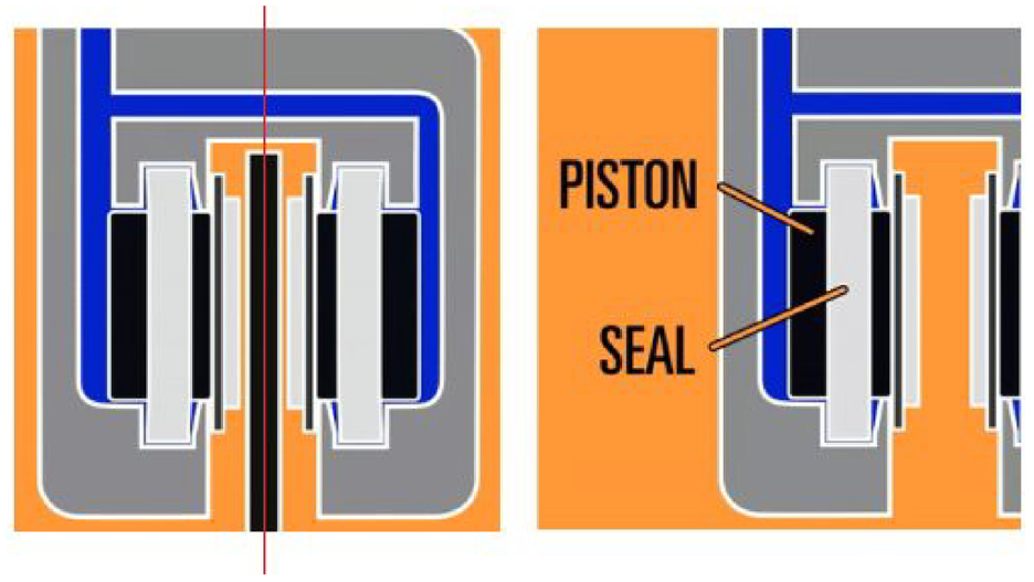
In contrast, hydraulic disc brakes use pressure to transmit power through the brake line to the caliper to drive the mechanism shown in Figure 3. When the piston on the brake lever pushes hydraulic fluid into the caliper, the hydraulic fluid drives the piston through a small hole. Both piston sides move together, creating friction between the disc and the brake disc. Force is then exerted through the brake lining, which causes the brake to clamp down on the brake disc. The disc is connected to the wheel, and the wheel slowing also slows the bicycle. Hydraulic disc brakes do not suffer cable fatigue, but when the lining is worn out, the piston automatically withdraws to maintain clearance. Overall, hydraulic disc performance is superior to mechanical disc brakes.
Bicycle hydraulic disc brake caliper system.
Designing a bicycle braking system using a switching solenoid valve
This study presents the design of a solenoid valve with a compact form factor, which is different from another system researched by. 1 This study measures less than 40 mm in length and has a diameter that meets the requirement of bicycle brake systems. The excitation of the solenoid valve produced a maximum attraction force greater than 200 N, and various magnetic properties, including magnetic lines, flux density, and power, were analyzed in different geometric dimensions. The design approach allowed for the production of nonlinear high-force output and the targeted force/stroke characteristic could be obtained by determining the appropriate design dimensions. A novel plunger design, which differs from standard switching solenoid valves, was also developed and illustrated in detail in Figure 4, along with the selected magnetic materials and permanent magnets. Commercial JMAG software was utilized to calculate the necessary dimensions of the linear motor to achieve the high force output requirement. The design procedure using JMAG is described in the subsequent section.

Exploded 3D view of the proposed ABS solenoid valve.
As shown in Figure 4, the solenoid valve operates on a precise principle involving multiple components. At the inlet, fluid enters the valve, awaiting control. The crucial element is the coil, which produces a magnetic field when energized by an electric current. This field acts on the spool or piston within the Pilot Diaphragm Mechanism (PDM). The spool’s movement is pivotal, as it regulates the flow path, determining whether the valve is open or closed. This orchestrated process directs the fluid through the intricate network within the valve, ultimately guiding it to the outlet. The synchronized interplay of these components allows for efficient and controlled fluid flow in various applications.
Original design solenoid valve structure
Using the FEM software package JMAG, a novel electro-mechanical switching solenoid valve was designed. Generally, conventional designs are based on an equivalent circuit approach, but trial-and-error in such cases can be very time-consuming. 21 Adopting JMAG means new ideas can be tested quickly, and repeated iterations of varying prototypes can be examined. The process of building the research domain by generating the required points is depicted in Figure 5. A two-dimensional cylindrical coordinate model of the magnetic field was utilized to quantitatively analyze the plunger’s output force because the linear motor’s geometry is axis-symmetric. 35 The finite elements are computed by JMAG’s automatic mesh generator, as shown in Figure 6. The value of the excitation current and the magnetization (B-H) curves for various magnetic materials must be supplied before simulations can be performed. The former can be acquired from matching magnetic material catalogs and is a known input signal. The boundary conditions of this study presuppose that every field line is perpendicular to the boundary. It’s also important to note that a permanent magnet composed of a high magnetic rare-earth substance (NdFeB) was employed to produce the maximum magnetic force. The device’s associated remnant flux density was around 1.45 Tesla. With a 0.3 mm coil wire diameter and 520 turns, the coil produced a total winding resistance of 4.8 Ω.

The construction of the research domain by assembling the required elements.

Meshing in finite elements of the solenoid valve.
Improved solenoid valve design
The improved design depicted in Figure 4 retains certain aspects of the original structure, 36 such as relevant dimensions and critical positions. However, modifications have been made to minimize the required driving current while maximizing the magnetic force while maintaining the same material volumes. This study uses a lower voltage of 3.6 A for optimization compared to earlier research that used a voltage of 5.0 A. Table 2 provides details of the solenoid valve structure, highlighting adjustments to the angle of the plunger head and stop block. These modifications reduce the flux area when the solenoid valve is closed while preserving the original volume width and broadening the magnet support area. The system incorporates SUS420, a conductive stainless steel, to achieve this purpose, which enhances the magnet’s influence range.
Comparison of the design.


Changes to the internal geometry of the coil have improved the critical dimensions outlined in Table 2. The boldfaced text in Table 2 indicates the differences before and after the structural improvements, as well as the newly added material components in the new structure. These modifications establish conditions under which the coil can reduce the current, enabling targeted output power while utilizing the same material and number of turns. In addition, after the adjustments listed in Table 2, the angle of the critical dimension is altered to limit the increase of the corner resistance when the coil is closed while maintaining the device’s body dimensions and appearance.
Finite element analysis JMAG static simulation results
Static response of brake solenoid valve 2D
Through the FEA of JMAG simulations, the optimal dimensions for the proposed switching solenoid valve were identified and presented in Figure 6. Corresponding magnetic force lines were obtained and displayed in Figure 7, while the magnetic flux density near the winding point was derived and shown in Figure 8. The raw data value output for a particular excitation current made calculating the average flux density and the static force/stroke relation possible. The revised design is based on the original structure with adjusted and improved dimensions and critical positions that reduce the driving current and achieve the desired magnetic force using the same volume of material. Figure 8 depicts the improved solenoid valve structure, wherein the angle of the lifting head and the angle of the lifting head stop have been adjusted to achieve superior performance. This figure and the FEM simulation software for JMAG show the magnetic field distribution inside the valve for a displacement range of 0–3.5 mm with a 0.5 mm interval and at 5.0 A current. The flux of magnetic lines is indicated on the right side of every graph. The rounded magnetic lines show reduced resistance and increased magnetic thrust output.

Magnetic field lines for a 5.0 A input current.

Magnetic flux density (in Tesla) for a 5.0 A input current.
The flux density results depicted in Figure 8 indicate that the improved design exhibits a higher energy utilization than the original design, thus making it a superior approach. Further simulations can be conducted with varying input currents and plunger strokes. For example, Figure 9 shows the static force/stroke relationship for two different input currents, 5.0 and 3.6 A. Additionally, Table 1 provides the maximal output forces corresponding to distinct input current values for the linear motor. The primary design objectives are 225 N at 5.0 A and 280 N at 3.6 A, with a working stroke of 3.1 mm.

The brake solenoid valve’s numerical static force/stroke (input current: 5.0 and 3.6 A).
Static 3D simulation analysis of the improved solenoid valve
This section converted the 2D profile plans into 3D renderings for simulation. JMAG has inbuilt CAD software, which was used to improve the reliability of this study and demonstrate the consistency of the simulation results. The simulation results were conducted in quarter sections, and the 3D static response results are shown in Figures 10 and 11. These figures show that, as with the previous simulation, the magnetic force inside the improved version was more significant than the force found in the original. The different color tones demonstrate this in the figures, where red indicates a higher magnetic flux density.

JMAG 3D renderings of the original solenoid valve show magnetic flux density and lines.

JMAG 3D renderings of the improved solenoid valve show magnetic flux density and lines.
Comparison of JMAG static simulation results
The static response data of JMAG 2D and JMAG 3D simulations were compared, and the outcomes are shown in Figures 12 and 13. The curves obtained from the JMAG 3D simulations were observed to have some fluctuations, likely due to the simplification of meshing required to speed up the analysis. However, despite this simplification, the static response curves from the JMAG 3D models closely resembled those obtained from the more detailed JMAG 2D models, indicating that the 1/4 profile simulation approach is a viable option for getting results promptly.
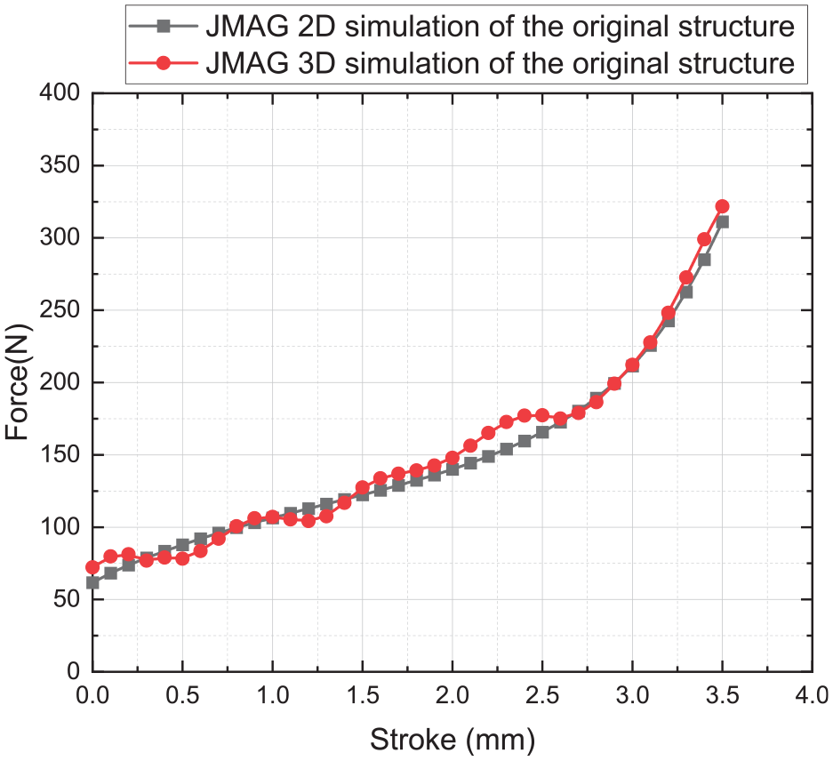
Simulated curvilinear forces of the original solenoid valve.

Simulated curvilinear forces of the improved solenoid valve.
Tables 3 and 4, respectively, analyze the data from Figures 12 and 13. Although the slope of the simulated data matches that of the original structure very closely, the error is controlled to within about 5%. For the improved model, the power of all three is similar in the first half of the blow, but bifurcation appears in the second half. This accounts for approximately 20% of the error described in Table 3. Despite this, the error remains within 5%.
Original structure static analysis collation table.

Improved static analysis collation table.

As shown in Tables 3 and 4, there are differences between the original structure and the improved static analysis collation table. Based on the equivalent circuit calculation, the maximum magnetic thrust produced by the enhanced electromagnetic coil is 260.71 N. The comparison of static magnetic thrust between the improved and original structures is attributed to optimizing geometric changes in the improved structure, which reduces magnetic reluctance and minimizes energy consumption while maintaining the original power output performance. Such findings have been validated through both software simulation (282.34 N) and equivalent circuit calculation.
Mathematical modeling
In the design and analysis process of bicycle brake solenoid valves, understanding their static response is of paramount importance. While static response analysis can be conducted through software simulations, deriving it using magnetic circuit model formulas provides a more intuitive and theoretically sound method. This paper will comprehensively detail how to establish the magnetic circuit model of the solenoid valve and calculate its static response.
In the mechanical model, Newton’s second law governs the plunger’s motion:


Where Fe is the electromagnetic force, Fs is the spring force, Fd is the damping force, Fg is the gravitational force, m is the mass of the plunger, x is the displacement, and t is the time.
The energy density U of the magnetic field inside the spiral can be expressed as 37 :
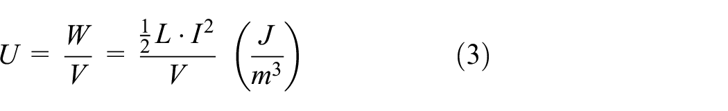
Where L is the Inductive (H), V is the Screw internal volume (
As shown in Figure 14, the magnetic circuit analysis is analogous to the circuit analysis. There are resistances in the circuit, and different materials in the course have different resistances Rm. The main magnetic lines are like electric currents and have different Rm when they pass through various areas. With the different resistances of Rm, the final magnetic force generated varies.

Schematic diagram of the area where the magnet wire passes through the different volumes of the solenoid.
By Ohm’s law of magnetic circuit:
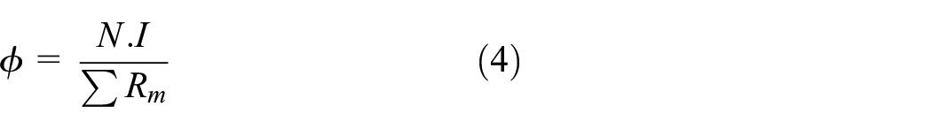
The relationship between magnetic suction force F and magnetic resistance Rm, the number of coils turns N, current I, permeability μ, and plunger cross-sectional area A can be obtained as follows:

There are some calculations in magneto-resistive, which can be categorized into three forms: (a) Axial flux; (b) Radial flux; and (c) The rotation angle is shown in Table 5.
Three main types of magneto-resistive calculations. 38

In addition to simulation software, the static response of a solenoid can also be analyzed using the magnetic circuit model formula. This involves establishing a magnetic circuit model for the solenoid, along with determining the permeability coefficient μ of each material element. The equivalent reluctance of each material component can then be calculated using the circuit resistance relation. The magnetic suction force F and working stroke relationship can be obtained through equation (5). This approach offers an alternative method for analyzing the static response of solenoids, which may be helpful in situations where simulation software is not available or feasible to use.
Referring to Figure 15 and Ohm’s law of the magnetic circuit in Table 3, the study calculates the resistance values in area (A)–(R). Aa∼Ar indicates the area perpendicular to the magnetic flux φ flowing through the area. Ra∼Rr shows that the working stroke is also the reluctance of the air gap, which has different reluctance changes with the stroke change. Therefore, the position change of the reluctance between Rg and Ro can be written as a functional relationship, 31 and Rf is written as another functional relationship.

Where y: working stroke: 3.1 mm; y0: plunger movement distance.

where y is the working stroke, which is 1.35 mm, and y0 is the distance the plunger moves. The displacement is not calculated if it is greater than 1.35 mm.

Equivalent circuit model of bicycle brake solenoid valve.
The relationship between the operating stroke and the reluctance function gives the total reluctance

The number of coil turns (N = 520 turns) and the operating current for drivers (3.6 A) are known from the previous results. The coefficient of permeability μ is taken as the air permeability

Through the geometric design of the solenoid described in this paper and subsequent magnetic reluctance calculations, the relationship between magnetic force and working stroke is shown in Figure 16. It can be observed that the equivalent magnetic reluctance of the original structure closely matches the curve obtained from JMAG 2D simulation data. At a working stroke of 3.1 mm, the maximum magnetic force is F = 260 N. Comparing the calculated values with the simulation results, the trend lines are very close, with an average error of approximately 4.5%. This demonstrates that the improved solenoid valve effectively utilizes geometric modifications to reduce the generation of magnetic reluctance.

Curves of calculated static magnetic resistance of equivalent reluctance compared with JMAG simulation.
Dynamic response simulation analysis
The dynamic response of a solenoid valve is the time required for the plunger head to move after the excitation of the solenoid, which is particularly crucial for braking applications. A circuit and program design must be integrated into the simulation software to conduct a dynamic simulation. The circuit schematic in Figure 17 comprises two components, with the solenoid represented by the lower black part, which includes a reverse voltage to facilitate solenoid closure. JMAG is employed to simulate the dynamic response of the solenoid valve and validate its response speed.

Dynamic circuit diagram constructed in JMAG for testing.
In Figure 18, various components of the solenoid circuit are shown. The first section, shown in Figure 18(a), is the primary circuit structure consisting of a voltage source V1, switch CS1, FEM (coil), capacitor C1, and diode D1. The role of diode D1 is to discharge the electromagnetic coil when the switch is opened, thereby protecting the coil. The second section of the circuit, depicted in Figure 18(b), adds voltage source V2 to output negative voltage when the solenoid valve is closed. This speeds up the return travel of the lifting head to its home position.

JMAG dynamic circuit diagram: (a) Part I, (b) Part II, (c) Part III.
The third part of the circuit, shown in Figure 18(c), is a logic control program written with four main inputs: total current supply, current limit, run-time, and stop-time.
Four variables (i)–(iv) control the switching of CS1 and CS2 at the output. The control method uses JMAG’s built-in program box CCB1 (Current Control Box), which can be used to write the program format and derive many different control conditions. In addition, the system uses Python language.
Solenoid current: detect the current condition. (Total current supply.)
Limit output current: Limit solenoid current. (Limit-current.)
Actual run time: Import the current software’s action time. (Run-time.)
Cut-off: power-off. (Stop-time.)
The program structure controls the current is greater than the limit current. The cut-off time is reached when the first switch is disconnected and both switches are closed simultaneously. Because the controller is built into the JMAG software, it is impossible to make the instructions too complex. The system here is sufficient for general logic control, but combining it with other applications, such as NI LabVIEW and MATLAB, would be possible.
JMAG dynamic simulation analysis of finite elements and boundary elements
A JMAG analysis of the original and improved devices was performed. The limiting current was maintained at the same level as the static analysis setting. The complete analysis parameters are presented in Table 6. This table also shows the lifting head closure’s response time, current variation, and force curve magnitude. This makes verifying the effect of the changes made during modification possible.
JMAG dynamic simulation parameters.

In Figure 19, the solenoid valve’s original structure is simulated, and the black line represents the current curve (A), while the red line represents the plunger stroke (mm). The simulation shows that the maximum solenoid current remains at around 5.0 A (maximum), and it takes approximately 9 ms for the plunger to complete the opening action. The voltage is cut off within 30 ms, and the current decreases rapidly due to the negative voltage. As the current approaches zero, the displacement gradually decreases, consistent with the actual device. Figure 20 shows the force curve during the dynamic response, and when the current limit is 5 A, the force is maintained at approximately 300 N, similar to the static stimulation.

Dynamic current and displacement response of the original device.

Output force response of the original device.
Figure 21 shows the dynamic response of the improved solenoid valve, where the maximum input current is 3.6 A, and the plunger head responds at approximately 13 ms. The control program switches the power supply at 30 ms, which is consistent with the original device. However, due to the rapid drop of the negative voltage, the plunger head displacement stroke is shorter, resulting in an increased influence range with the magnet and a faster drop speed than the original device. Figure 22 displays the output force at about 250 N, which is lower than the static response force. This can be attributed to the lower current, where the current limit of the instantaneous switch is more easily consumed than at higher currents, leading to a softer solenoid valve force. However, the dynamic force still meets the target of 200 N despite being less than that of the static simulation.

Dynamic current and displacement response of the improved device.

Output force response of the improved device.
Experimental results of the ABS brake solenoid valve
In this study, two experimental test device platforms were designed and constructed to evaluate the performance of an ABS solenoid valve. The first test device was a static test rig, as depicted in Figure 23, which incorporated an open-loop controlled micro-stepping motor to regulate the position of the plunger in conjunction with a linear motor. The quantity and frequency of the generated pulse signal provided to the driver directly dictated the rotational angle and speed of the micro-stepping motor. A Hi- (5 V) or Lo- (0 V) signal was sent to one of the driver’s input ports to regulate the direction of rotation. A position sensor (LVDT) and a load cell were utilized to measure the plunger’s stroke travel and output force. Finally, the LabVIEW software integrated all unit control and measured data acquisition and processing. A dynamic test device was used for the second test, as shown in Figure 24. The linear motor’s output plunger drove a mass-spring-damper system to replicate the motion of a spool in a fluid and a power level proportionate to the valve body. A digital optical-linear scale was used to measure the mass’s displacement. Similar to the first test, data acquisition was recorded, and the device was operated using LabVIEW software.

The static force/stroke test device.

The dynamic test device.
The electromagnetic coil dynamic response test stage assumes that the mass block is the spool in the valve body, where the mass block has a group of 107 g, and the spring is the feedback spring in the electromagnetic valve. In this stage, the plunger head pushes the spool (Mass) to capture the rise time of the displacement action after excitation.
In this study, an enhanced bicycle brake solenoid valve was developed and a prototype was fabricated for comprehensive testing, as illustrated in Figure 25. The device’s static force curves and dynamic reaction speeds were meticulously measured using a self-assembled test bench with a matching control circuit. A constant current power supply ranging from 0.1 to 3.6 A powered the solenoid, and the actual static magnetic thrust was measured with the fixed test bench. Due to machining and assembly errors, frictional force was generated as the solenoid plunger moved against the internal sleeve components, resulting in force losses. The experimental results showed a discrepancy of about 8% between the measured and simulated values as shown in Figure 26, achieving the target output force of the solenoid valve designed in this paper.

The realized prototype of ABS solenoid.
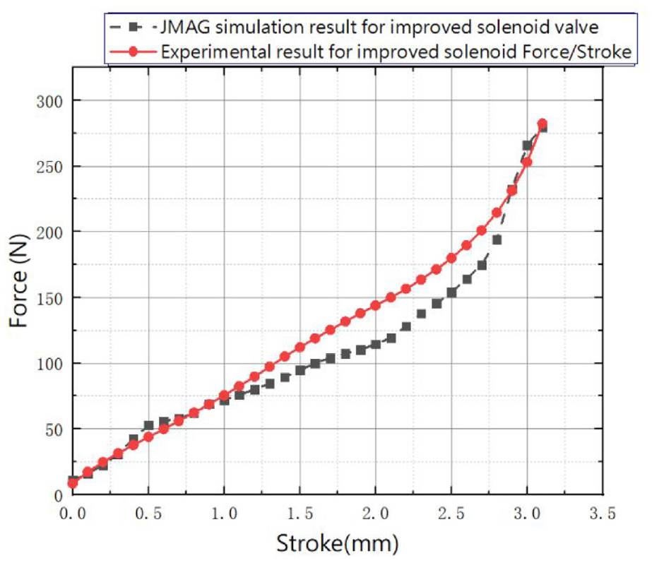
Experimental force/stroke curves of the prototype solenoid valve.
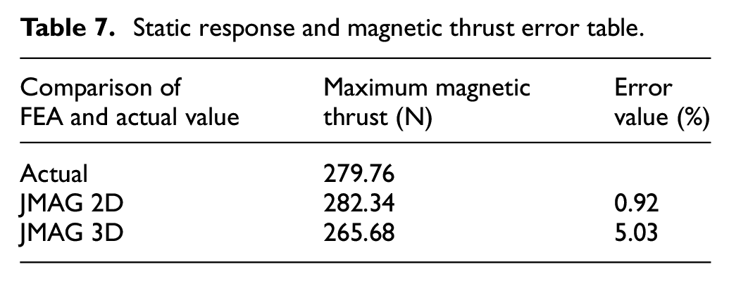
The measured data of the improved solenoid valve was compared with both simulated and calculated data and the maximum static and dynamic response times were extracted to evaluate the error. Table 7 shows the full magnetic thrust, where the error between the results calculated by the magnetic circuit theory and the actual measurement results is 6.8%. This could be attributed to the magnetic circuit model being calculated with a larger area than the actual area considered. Regarding the simulation results, the JMAG 2D & 3D simulations closely matched the actual measurement data, and the error between the simulation values and the actual results was within 5%.
Static response and magnetic thrust error table.
The dynamic performance of the improved solenoid valve was evaluated using a dynamic test bench that excited a mass block. The results were verified with a high-speed oscilloscope. The response time and current turning point were higher than the simulated values, likely due to more complex environmental factors such as friction, energy loss, and measurement error in actual dynamics. However, the deviation between the real and simulated values was minimal. Table 8 summarizes the differences in dynamic performance between the actual and simulated solenoid valves.
Dynamic response time error table.

The improved electromagnetic valve was installed on the dynamic test bench to test the excitation and pushing of the mass block, with the response time and current inflection point measured by an oscilloscope (Figure 27). Figure 28 shows that the dynamic test response time is approximately 13.8 ms when a minimum excitation current of around 0.2 A is applied to the electromagnetic coil. The current variation reaches a maximum of 5.5 A when the maximum current is applied. The driving current is 4.2 A, indicating that the coil is energized with the most significant magnetic circuit air gap, air gap resistance, and smallest inductance. The changes in each section are explained below:
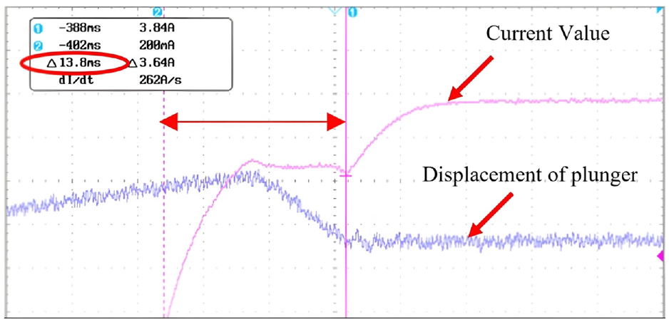
Actual dynamic test response time for the improved device.

The proposed linear motor’s typical step response at 4.20 A current.
Conclusion
This study utilized JMAG-Designer to design and analyze two geometrical sizes of ABS solenoids, focusing on their static and dynamic output characteristics. The prototypes were modeled with simplified response equations and validated through both simulation and experimental testing using a custom-built solenoid test platform. Key findings include:
Performance Improvement: The improved ABS solenoid valve exhibited superior performance compared to the original, maintaining a maximum magnetic thrust force of 280 N while reducing the required current by 28% (from 5.0 to 3.6 A).
Accuracy of Simulation and Experimentation: The simulation and experimental results were closely aligned, with a margin of error within 10%, confirming the reliability of the design and testing methods used.
Prototype Fabrication and Testing: The improved solenoid was successfully fabricated and its dynamic and static response values were accurately measured. Despite a slight increase in response time to 13.8 ms, the device remains suitable for practical applications.
Future Applications: The enhanced electromagnetic coil structure, validated through both software simulation and physical testing, shows promise for integration into future ABS systems for bicycles, offering improved efficiency and performance.
Developing the magnetic circuit model for the bicycle brake solenoid valve and calculating its static response not only facilitates the design and optimization of the solenoid valve but also enhances its overall performance. This improvement ensures the safety and reliability of the bicycle brake system, contributing to a better user experience. By integrating theoretical analysis with practical application, we can continuously innovate and advance the technology of bicycle braking systems.
Overall, the study demonstrates significant advancements in ABS solenoid valve design, combining reduced power requirements with maintained performance, and highlights the potential for real-world applications in bicycle ABS systems.
Footnotes
Handling Editor: Aarthy Esakkiappan
Declaration of conflicting interests
The author(s) declare that there is a potential conflict of interest regarding the research, authorship, and/or publication of this article: This research was funded by the National Science and Technology Council (NSTC), Taiwan R.O.C., which has an interest in the outcome of this research. The funder provided financial support but did not participate in the study design, data collection and analysis, decision to publish, or preparation of the manuscript.
Funding
The author(s) disclosed receipt of the following financial support for the research, authorship, and/or publication of this article: The authors thank the financial support from the National Science and Technology Council (NSTC), Taiwan R.O.C., under grant number NSTC 111-2221-E-224-053 and This work was supported by the Ministry of Education and National Yunlin University of Science and Technology’s Higher Education Sprout Project.