
Abstract
Disc brake performance is an important guarantee for the safe operation of high-speed trains. Brake pad fastener snap rings may fail during train braking, causing the friction body to fall off, which is a serious threat to the safety of train operation. This article establishes a finite element model of brake pads/discs taking into account the thermal-mechanical coupling field in the braking process. The temperature distribution of the brake disc surface, the displacement and stress results of the snap rings at different positions are investigated. The results show that the temperature of the brake disc rises and then falls during braking, and the surface temperature of the brake disc is spread in the form of an annular band. The highest displacement and stress variations are found in the snap ring group around the speed entrance area and the inner side of the brake pad. In the x and z directions, the average displacement changes are 0.1967 and 0.1233 mm, respectively. The average changes in contact stress and internal stress are 9.8 and 15.5 MPa. The results of the service behaviour of the snap ring provide a basis for the study of snap ring failure.
Keywords
Introduction
The braking performance of high-speed train brake pads in the braking process is crucial. A high-speed train braking pad is shown in Figure 1. The brake pad uses a snap ring to fasten the components, and the service behaviour of the snap ring affects brake pad performance. The snap ring is essentially an elastic element. It controls the movement and positioning of components by converting elastic potential energy into mechanical energy using its structural properties. The high-speed rotating brake disc and the brake pads come into contact while braking, producing a tremendous amount of heat. Heat causes the material at the friction interface to expand, which causes the individual brake pad components to rotate and make unstable contact with one another. The snap ring is in close contact with the components as a fastening element. The elastic balance of the snap ring is broken as a result of the rotational displacement of each component during the braking process. In extreme circumstances, the friction bodies of the brake pads may come off due to snap ring failure, which will impair the performance of the brake pads and jeopardize the security of high-speed train operations.

High-speed train brake pad: (a) front side (b) back side.
The fastener snap ring failure phenomenon shows itself as popping out of the brake pad or directly breaking and falling when a high-speed train is braking. It is only discovered that the snap ring of the brake pad disappeared during routine train maintenance. An analysis of the altered service behaviour of the snap rings during train braking is required to identify the reasons behind snap ring failure. The braking process of the train is a complex coupling field, making it challenging to directly test different data using traditional experimental methods. In contrast, the finite element simulation method is less expensive, does not depend on outside interference and produces a variety of output results. It is ideal for researching the way snap rings behave when braking.
Disc brakes use friction between the brake pad and disc to produce braking, its braking efficiency is influenced by the distribution and patterns of change in friction heat and contact stress at the friction interface. 1 Wang et al. 2 studied the temperature evolution of train brake discs during high-speed braking through field tests, theoretical analysis and finite element modelling. Temperature changes caused corresponding fluctuations in the instantaneous friction coefficient and thermal stress distribution in the disc surface, thus producing thermal damage. Hong et al. 3 conducted thermo-mechanical friction analysis on brake discs and brake discs to find out the causes of thermal cracks and verified the analytical model through a generator. Wang and Zhang 4 conducted a numerical simulation on the thermal failure of a wet multi-disc brake during emergency braking caused by thermoelastic instability caused by thermomechanical coupling and obtained the contact pressure distribution, temperature field and stress during the emergency braking field. The results show that during emergency braking, the temperature at the outer diameter of the friction plate is high, and a large temperature gradient and stress gradient are generated at the edge of the radial groove, causing the friction plate to warp. Belhocine and Abdullah5,6 tested three different brake disc materials and conducted a comparative analysis of the test results to determine which brake disc material had the best thermal performance. He also used the genetic algorithm (GA) and particle swarm algorithm (PSO), the two most accurate and widely used evolutionary optimization algorithms, to determine the optimal design parameters of ventilated brake discs. Ahmad et al. 7 found the most suitable material based on thermo-mechanical analysis, which can not only maintain heat generation but also withstand other mechanical loads. Juraj et al. 8 elaborated on the temperature rise problem of friction elements during the braking process and proposed a temperature stabilization method at the contact point of the tribological elements during the braking process. To reveal the contact characteristics of the hydraulic brake friction pair in the initial stage of the braking process. Qingrui et al. 9 conducted a numerical analysis of the contact characteristics of the friction pair, including the change rules of contact surface temperature, contact stress and heat flow density. The theoretical analysis has been verified by experiments. Topczewska10,11 based on the known unsteady temperature field, determined the spatial and temporal distribution of the quasi-static temperature stress of the friction element and analysed the impact of the friction power time history on the disc stress state. The results show that at the end of the braking process, tensile normal stress is formed on the working surface of the brake disc, which may lead to radial cracks on the surface. The nominal value of the contact pressure in the contact area between the cermet pad and the cast iron disc was studied. The effect of time on temperature, the maximum temperature decreases linearly with the time to reach the nominal value of the contact pressure, and the time to reach this temperature increases. Belhocine 12 investigated the finite element approach of the brake disc/pad contact behaviour with thermal effects and reported the expected temperature distribution, deformation, stress and contact pressure.
Unstable contract performance during the braking process will produce undesirable torque between components, which will have a negative impact on the service environment of the fastener and affect its service performance. Qu et al.13,14 established a three-dimensional thermal-mechanical coupling model of high-speed wheel-mounted brake discs including bolted connections and contact relationships, which provided support for the design of brake discs and connecting bolts. They tested at different initial speeds of Axial load on the bolts connected to the brake disc under emergency braking conditions. A finite element model was established to analyse in detail the evolution of the bolt axial load during the braking process. The results show that as the initial speed of emergency braking increases, the variation range of the axial load of the bench test bolt first increases and then decreases. The simulated bolt axial load variation range is 55.5 kN, and the error is 7% compared with the test. Zeng et al. 15 studied the longitudinal resistance characteristics of WJ-8 fasteners under different torques and vertical loads. Hess 16 analysed the loosening moment under the action of axial external load, gave a calculation example and defined the fastener locking requirements. Ishak et al. 17 found that the brake torque slightly increases as the drum brake temperature increases. Cui et al. 18 studied the fracture mechanism and control method of fastener spring bars in the high-risk section of rail corrugation, established a numerical simulation model of the wheel-rail-fastener system, considered the resonance response and fatigue failure of fastener spring bars, and explored The fracture mechanism of fasteners and corresponding control methods are proposed. Li et al. 19 studied the causes of rail corrugation. Research results show that short-pitch rail corrugation is caused by the wavelength-fixing mechanism of vertical rail bounce on elastic fasteners. The corrugation wavelength is mainly related to the vertical stiffness of the rail fasteners. Gao et al. 20 took the W300-1 fastener as the research object, tested and summarized its service performance and online track mode identification, and obtained the dynamic characteristics of fasteners with pre-tightening force under temperature-related and frequency coupling conditions. Research has found that the stiffness of the elastic backing plate in the fastener system is sensitive to low temperatures and high frequency. Huang 21 found that the elastic force of the U-shaped snap ring of the CRH2A EMU brake plate support became weak and could not closely adhere to the gear iron. The snap ring could even be opened with bare hands without using tools during maintenance. Zhen 22 analyzed the failure of the input shaft snap ring of the wind power yaw reducer and found that the friction between the various parts was too frequent, resulting in the snap ring and the groove not being better connected and running in during operation changes, resulting in the snap ring fell off. Ji et al. 23 studied the wind power yaw reducer and found that passive yaw is the main reason for the failure of the snap ring.
Scholars have studied the problems caused by frictional heat generation during the braking process. According to the research, brake components may experience undesirable occurrences like heat cracks, which could impair their ability to function. Frictional heat generation can also lead to poor contact performance, resulting in poor torque leading to a poor service environment for the fastener. The study summarized the fastener load change rule and fasteners can not be normal service caused by the adverse consequences. However, few studies that examine how thermal coupling fields during braking affect the service behaviour of the snap rings. The heat and torque of the friction interface force the parts of the brake pad to rotate, which negatively affects the service environment of the fastener snap ring. In extreme circumstances, the snap ring may fail and the friction body of the brake pad may fall off, endangering train operating safety.
This article examines the service behaviour variations of the snap ring during the train braking process in an attempt to identify the causes of the failure of the brake pad fastener snap ring on high-speed trains. A proportional brake pad/disc brake finite element model is created, taking into consideration the acquisition and imparting of the snap ring pre-tightening force as well as the thermal-mechanical coupling effect throughout the braking process. The primary emphasis lies in the alterations in the service behaviour of the snap ring caused by the displacement of the brake pad components. The displacement and stress change regulations of the snap ring are derived from the analysis results, and their connection to the thermal load during the braking process is established. The suggested approach and the outcomes offer insight and a basis for further research into the issue of snap ring failure.
Load during service of snap ring
The brake pad fastener snap ring plays a role in connecting the steel back, support positioning seat and friction body and fixing the position of the components during service. Pre-tightening force is supplied by the snap ring in both the axial and radial axes. The high-speed spinning brake disc and the brake pads make contact throughout the braking process. As a result, the snap ring bears a variety of adverse loads, namely impact and braking torque, which have an impact on the axial and radial service of the snap ring.
Braking torque
The primary source of braking force for disc brakes is the contact friction between the brake discs and brake pads. The braking torque is produced by the frictional contact force between the components.

The braking torque will produce a radial load on the fastener snap ring.

Where F is the braking thrust of the brake pad, Dt is the friction radius corresponding to the snap ring at different positions, μ is the friction coefficient between the brake pad and the brake disc and i is the number of snap rings.
Impact load
The IEC 61,373 standard is used to determine the impact load. The maximum impact acceleration in all directions for components mounted on shafts is 1000 m/s 2 . The purpose of the fastener is to prevent the steel back, support positioning seat and friction body of the brake pad from separating from one another when subjected to an axial acceleration of 1000 m/s 2 . This separation is caused by inertia. The axial load sustained by each snap ring is determined by equation (3).
When subjected to a radial acceleration of 1000 m/s 2 , it should be ensured that the steel backing, support positioning seat and friction body in the brake pads do not undergo relative sliding. The radial load sustained by each snap ring is determined by equation (4).

Where mfr is the mass of the parts to which the brake pad is fastened, a is the impact acceleration and i is the number of snap rings.
Calculation of brake pad fastener snap ring pre-tightening force
A unique fastener that is essentially an elastic component is the snap ring. In order to guarantee that it has a pulling impact on the friction body during the braking process and fulfills the purpose of tightening, it must be tooled before being formally placed into service to obtain pre-tightening force. To ensure that the snap ring has an initial pre-tightening force in the brake finite element model, the snap ring must be imported into the model in a deformed form and assigned an initial state. Modelling in this way has advantages. On the one hand, the accuracy of the simulation results is guaranteed by the fact that it closely resembles the real scenario and reflects the realism of the model. On the other hand, it reduces computation time and resource waste. The pre-tightening result of the clamp spring can be applied to any working condition, avoiding duplication of work.
Brake pad structure
The friction body, steel backing, snap ring and support positioning seat make up the brake pad. There is 1 steel back, 6 support positioning seats, 18 friction bodies and 18 snap rings altogether. Each support positioning seat, three friction bodies and three snap rings make up a group. The braking pressure is applied to the steel back through the brake piston, transmitted to the friction body through the support positioning seat, and comes into contact with the high-speed rotating brake disc to generate braking force.
A unique structure of the brake pad is formed by the friction body, the support positioning seat and the steel back adopting a ball pair type contact, as seen in Figure 2. These components of this contact type have gaps between them. When the brake pad comes into contact with the high-speed rotating brake disc during the braking process of high-speed trains, the static friction force is changed into sliding friction force, damaging the balance of each component. Friction heat is also produced on the contact surface between the brake disc and the friction body. The material swells when heated to high temperatures, creating an unstable contact between the friction body and the brake disc. The ball pair contact between the floating structure can cause the friction body and the support positioning seat to distort and deflect. Stable braking performance is ensured by the floating structure, which keeps the friction body and brake disc in close touch with one another throughout the braking process.

Cross-sectional change diagram of floating structure.
There are three friction bodies and three snap rings in the support positioning seat. The pin portion is attached to the guide hole of the steel back in order to perform a positioning function that restricts each group of friction bodies’ range of motion and guarantees the stable contact of each group of friction bodies. A crucial element linking the friction body and the snap ring is the support positioning seat, whose displacement changes during braking will impact the friction body via the floating structure and alter the elastic balance of the snap ring.
Basic assumptions and boundary conditions
The following assumptions are taken in the process of establishing the finite element of the snap ring tooling, taking into account that the tooling is simply utilized to acquire the pre-tightening force of the snap ring for future braking analysis.
(1) The snap ring is a flexible body component, and the other components are set as rigid bodies. The force deformation of other components and their impact on the pre-tightening quality of the snap ring is not considered.
(2) In order to avoid unnecessary damage, it is assumed that the friction coefficient between components is 0.2, and the wear during the assembly process of the snap ring is not considered.
(3) Since the tooling process of the snap ring is short and the energy is small, the friction and heat generation between components and their impact on the pre-tightening quality of the snap ring are not considered.
The snap ring tooling process is divided into two steps. (1) Use the pressing block to completely press the snap ring into the groove of the steel back. The purpose is to force the snap ring to deform. The deformation energy is transformed into mechanical energy to produce a pre-tightening force based on its elastic structural properties. (2) Using the pre-tightening force obtained, the snap ring fixes the friction body to accomplish the tightening goal after a predetermined length of time, depending on its structural features and interaction between the brake pad components.
The boundary conditions for the finite element of the snap ring tooling are established in accordance with the numerical simulation plan of the snap ring pre-tightening force. The guide rod, steel back, support positioning seat and friction body are completely fixed, that is, U1=U2=U3=0, UR1=UR2=UR3=0. Only downward displacement is applied to the pressure block, and the other directions are restrained, that is, U1=U3=0, UR1=UR2=UR3=0, and the value of U2 is the downward displacement of the pressure block. The boundary condition settings for the snap ring tooling finite element model are displayed in Figure 3.

Finite element model of snap ring tooling.
Analysis of snap ring tooling results
The stress cloud chart of the snap ring tooling is shown in Figure 4, and the stress cloud chart of a single snap ring is shown in Figure 5. The snap ring has a good overall stress condition and is capable of blocking the friction body. Its maximum stress result, 611.7 MPa, is a local flash point value. The location is where the snap ring and pressure block come into contact. Here, the pressure of the pressure block creates the local stress flash point. The maximum stress value of the snap ring mostly occurs in the radius expansion area, which is subject to the expansion pulling force. Secondly, it is at the contact area between the upper plane of the snap ring and the pin at the upper end of the friction body, where the snap ring provides upward pulling force to tighten the friction body. With the local stress flash point value of the snap ring excluded, the overall stress is around 360 MPa, and the stress yield value of the snap ring material is 605 MPa, which is less than the yield strength. It is thought that brake simulation can be performed using the snap ring tooling results.

Stress cloud diagram of snap ring tooling results.

Pre-tightening form of a single snap ring.
Establishment of finite element model of brake pad braking process
Finite element thermal-mechanical coupling analysis method
The sequential coupling method and the direct coupling method are the two primary approaches used to investigate the thermal-mechanical coupling in disc brake braking. In order to ascertain the heat flow density input on the contact surface of the brake disc and friction plate, the basic idea of the thermal sequential coupling method is to first compute the heat energy converted and absorbed by the disc brake during vehicle braking using the energy conversion method. Next, use thermal analysis on the brake to determine the temperature of every brake node. Lastly, the brake structural model’s stress field is examined by applying the nodes’ thermal analysis results as thermal loads. This analysis approach solely takes thermal deformation into account in relation to the brake temperature field. It ignores the fact that thermal deformation will have an impact on the heat flux input to the contact surface and the contact pressure, both of which will influence how the brake temperature field is distributed. In addition to taking into account how the temperature field affects thermal deformation, the thermal direct coupling method takes into account how the brake’s thermal deformation alters the contact state and contact pressure between the friction pairs. These changes in turn have an impact on the heat flow density input to the friction pairs’ contact surface, which alters the temperature field of the brake disc. More accurate simulation results can be obtained by using the thermal direct coupling method. However because the analysis steps are too small, the analysis and calculation times are significantly increased. Thus, in emergency braking situations, the majority of ongoing research employs the thermal direct connection approach for disc brakes. The thermal sequential coupling method is applied to simulations under continuous and long-term braking situations. In this work, the high-speed train is braking with a single brake condition and a brief braking duration. To achieve more accurate outcomes, the thermal direct coupling technique is employed. A flow chart for the thermal direct coupling method is shown in Figure 6.
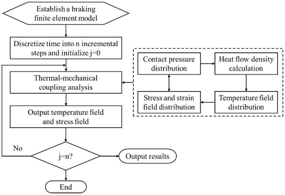
A flow chart for the thermal direct coupling method.
Basic assumptions
When creating the brake finite element model, the following presumptions are made because the finite element simulation cannot be entirely compatible with the real working conditions.
(1) The friction heat flow coupling is taken into consideration in order to solve the distribution problem of friction heat flow between the disc and the brake pad. The contact interface between the brake disc and the brake pad is thought to be an ideal plane, and there should be identical instantaneous temperatures at each location on the interface within the contact region.
(2) During braking, friction conforms to Coulomb’s law. Assuming that the coefficient of friction at the brake contact interface remains constant and the train moves with uniform deceleration
(3) It is thought that all friction work is transformed into friction heat, regardless of the effect of material wear.
(4) The materials of the brake disc and brake pad are isotropic, and the materials only undergo linear elastic deformation.
The finite element model is practicable because it fully takes into account situations like convection conduction, thermal convection and thermal radiation, and it includes fundamental elements like rotational speed variations, frictional heat generation and brake pressure during braking.
The relevant material parameters of each component of the brake pad and the brake disc are presented in Tables 1 and 2. 24
Material properties of each component.

Material parameters of brake discs changing with temperature.

Basic theory of thermal-mechanical coupling
Frictional heat flux
Huge amounts of heat are produced by the disc brake when it comes into contact with friction. The surface of the brake disc and brake pad is supplied with friction heat flow density that satisfies 25

For the braking disc and brake pads, the heat flow densities that are delivered to them are


Where q1(r,θ,t) and q2(r,θ,t) are the heat flux densities on the surface of the brake disc and brake pad respectively, η is the proportion of heat flow absorbed by the brake disc to friction heat energy, μ is the friction coefficient, p(r,θ,t) is the friction surface pressure and v(t) is the relative speed of the brake disc and brake pad.
Heat transfer method
Thermal conduction, thermal convection and thermal radiation are the three transfer modalities for the heat produced during braking, as determined by the actual braking conditions of high-speed train disc brakes. Among these, thermal conduction is the primary means of internal heat transfer for the materials that make up the brake disc and brake pad, and it also predominates in the area where the surfaces meet. Convection is the primary heat transfer mechanism between the brake’s non-contact area and the surrounding air. Another significant method of heat energy exchange is thermal radiation, which is brought on by the high temperatures created during the braking process. 26
During heat conduction, the heat flux density q of each cross-section is shown in the formula.

Where q is the heat flow density, λ is the thermal conductivity of the material, T is the temperature of the material, and ∂T/∂n is the temperature gradient in the direction normal to the boundary and the negative sign on the right side of the equation indicates that the direction of heat transfer is opposite to the direction of the temperature gradient.
When a fluid (gas or liquid) moves away from a solid surface, heat is transferred through a process known as thermal convection. Convection heat transfer is calculated as follows.

Where h is the convection heat transfer coefficient, and ΔT is the temperature difference between the fluid and the solid.
Thermal radiation is the constant, non-mediating emission of electromagnetic waves into space by things with a temperature higher than zero. Objects will simultaneously take in radiation from other objects in the universe. The radiation is stronger the greater the object’s temperature. The following is the radiation heat transfer computation based on the Stefan-Boltzmann law.

Where ε is the thermal radiation emissivity of the radiating surface, which is generally considered to be no greater than 1, σ is the Stefan-Boltzmann constant and its value is 5.67 × 10⁻⁸ W/m2 K4, and T1 and T0 are the radiating surface and ambient temperature respectively.
Thermal stress calculation
Assuming that the object only creates linear strain owing to thermal expansion and that the shear strain is zero, the material only experiences linear elastic deformation. This strain resulting from thermal deformation can be thought of as the object’s original strain. Add the initial strain term to the stress calculation. 25

Where
In this case, the first strain in the stress-strain relationship is represented by

Where α is the linear expansion coefficient of the material,
Boundary conditions and meshing
Thermal boundary conditions
(1) Heat flow distribution coefficient
The total of the heat flows that enter the brake disc and the brake pad is the heat flow q that is produced by the friction of the high-speed train disc brake on the contact interface. The following formula is used to determine the distribution coefficient γ of heat flow between the brake disc and brake pad. 27

Where ρ is the density, c is the specific heat capacity, λ is the thermal conductivity of the material and the subscripts d and p represent brake discs and brake pads respectively.
The ratio η of the heat energy absorbed by the brake disc to the total friction heat energy is

(2) Convection heat transfer coefficient
Convection heat transfer is thought to be the primary mechanism in the field of braking for dissipating frictional heat energy, particularly near the end of braking. Three types of convection heat transfer during braking can be distinguished based on the principle of heat exchange, natural convection, forced convection and mixed convection. The convection heat transfer coefficient h of the brake disc surface can be determined by the Nusselt number Nu. 28

Where λ a is the thermal conductivity coefficient of air, Nu is the Nusselt number and d is the brake disc diameter.


Where Pr is the Prandtl number of air, Re is the Reynolds number, ρ a is the air density, μ a is the aerodynamic viscosity and v is the brake disc linear speed.
The formula shows that the size of the brake disc and speed have an impact on the convection heat transfer coefficient. The linear speed of the brake disc and the airflow rate both drop while braking occurs, lessening the heat convection effect and causing a change in the convection heat transfer coefficient.
Displacement boundary conditions
High-speed train braking structures are symmetrical about the brake disc thickness centre plane in practice. Just half is used as the research object in order to minimize the quantity of computation. Crucial parts of the brake finite element model are braking discs, friction bodies and snap rings. Their primary dimensions are listed in Table 3.
Key dimensions of key components of disc brake.

50 km/h and 13.5 s are the braking parameters. The brake piston applies a braking pressure of 23 kN, which is equivalent to 7.26 MPa. The explicit thermal-mechanical coupling analysis method is the analysis technique used. The brake disc is initially subjected to an angular velocity of 36.2 rad/s before the analysis starts, and a starting temperature of 20°C is chosen from room temperature. The steel back only releases the x-direction degree of freedom when the analysis begins. The other direction degrees of freedom are therefore limited, that is, U2=U3=0 and UR1=UR2=UR3=0. To ensure that the symmetrical brake pads on both sides have the same degree of freedom, x-axis symmetry and anti-symmetry restrictions must be added to the rear of the brake disc during the simulation of a single brake pad, that is, U1=UR2=UR3. To simulate the braking operation of a train, define the angular velocity amplitude curve for the brake disc such that it moves uniformly and decelerates.
Before computing the finite elements, the model needs to be meshed. The accuracy and computation time are directly impacted by the rationality of the meshing. The mesh density needs to be uniformly distributed before the mesh is divided. Verify the mesh quality after meshing. Higher solution efficiency and better convergence are associated with a lower number of harmful and erroneous meshes. Hexahedral meshes are typically used in braking discs and brake pads, with tetrahedral meshes being used in addition. A total of 883,009 meshes are included, with the unit types being C3D8T and C3D10MT, respectively. The boundary conditions of the finite element model are displayed in Figure 7, and the mesh details of each component are included in Table 4.
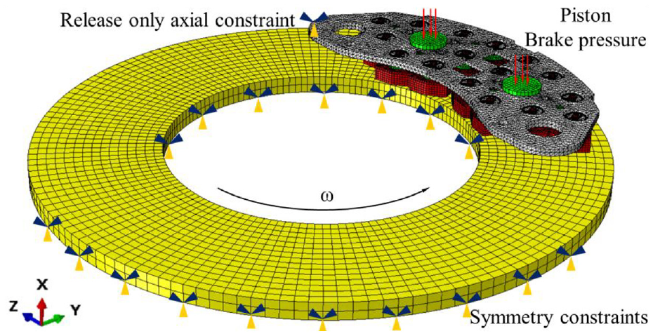
The braking finite element model.
Mesh information of finite element model components.

Number and group the snap rings
The support positioning seat serves as the pivot for the grouping of 3 friction bodies and 3 snap rings that make up the brake pad’s structural features. Eighteen snap rings are numbered and arranged together as seen in Figure 8. The snap ring is divided into the speed inlet area (groups IV and VI), the transition area (groups II and III) and the speed outlet area (groups I and V) based on the brake disc’s rotation direction. The snap ring is further divided into inner, middle and outer rings based on the brake disc’s diameter direction.

Snap ring position numbering and grouping.
Analysis and discussion of simulation results
Analysis of brake disc temperature results
The temperature cloud diagram of the brake disc surface at different times throughout the braking operation is displayed in Figure 9. Figure 9(a) shows that in the early stage of braking, the highest temperature band of the brake disc appears on the outside. Figure 9(b) shows that in the middle stage of braking, the brake disc forms three temperature bands. This is because the brake disc’s speed reduces with increasing braking duration, its exterior heat dissipates more effectively than its interior, and its interior temperature rises more steadily than its exterior temperature. The brake disc’s maximum temperature now shows up in the interior temperature zone. Figure 9(c) is at the end of braking, the brake disc temperature shows a flake distribution, which is a manifestation of the heat transfer effect of the brake disc.
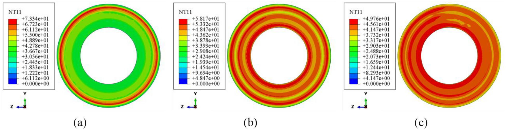
Brake disc temperature cloud diagram at different times: (a) 4.05 s, (b) 7.425 s and (c) 13.5 s.
Extract the brake disc surface’s highest temperature at each instant and plot it on a curve, as in Figure 10. The brake disc’s maximum temperature is 73.34°C at 4.05 s of braking, which is in the zone outside the disc. Because the heat dissipation effect is better on the outside of the brake disc than it is on the inside, the maximum temperature value of the brake disc shows an upward trend at 7.425 s. The highest temperature point of the brake disc appears in the temperature zone on the inside of the brake disc, and the value changes slightly. The maximum temperature of the brake disc demonstrated an overall tendency of initially rising and then falling during the entire braking procedure, which is in line with the real circumstances.

Maximum temperature curve of brake disc.
X-direction displacement change of snap ring
X-direction displacement phenomenon of snap ring
The snap ring produces mechanical force to tighten the friction body by structural deformation at the start of braking, and the warp height of the deformed snap ring is h1. Because of its rounded bottom, the snap ring is susceptible to the force and movement of the surrounding components when braking, which will cause a change in the snap ring’s x-direction displacement. The warp height of the deformed snap ring becomes h2 at the end of braking. Take the snap ring’s x-direction displacement cloud diagram at the beginning and end times. Because of the small change, the snap ring’s degree of warp is magnified ten times. Figure 11(a) shows a schematic diagram of the snap ring’s warp height decreasing in the x-direction, and Figure 11(b) shows a schematic diagram of the snap ring’s warp height increasing in the x-direction. Δh = h1-h2, Δh > 0, indicates that the component’s force applied to the snap ring decreases as the snap ring’s height decreases during braking. Δh < 0, on the other hand, indicates that the component’s force increases as the snap ring’s height increases during braking.

Displacement changes in the x-direction of the snap ring: (a) height decreases and (b) height increases.
Causes of x-direction displacement of snap ring
Due to the existence of a floating construction, there is a space between the steel back and the brake pad support positioning seat. The high temperature of the friction interface will have an impact on the performance of the contact during braking. There is instability in the friction body-brake disc interaction. This is sent to the support positioning seat, where it acts on the snap ring and modifies its displacement in the x-direction. The support positioning seat is a hub component and has the most obvious changes.
A cloud chart representing the displacement change of the support positioning base in the x-direction is shown in Figure 12. Figure shows that the warp of the seats in groups V and VI for support positioning is greater in the x-direction. The snap ring’s displacement in the x-direction will be impacted by the warping of the support positioning seat, and the degree of variation in the snap ring will vary.

Displacement changes in the x-direction of the support positioning base.
X-direction displacement results of snap ring
The x-direction displacement change of 18 snap rings throughout the braking process is given in mm, as Table 5 illustrates. The height at the beginning moment less the height at the end time is the change in the snap ring spring height during the braking process. In other words, Δh = h1-h2, where Δh is the change in the snap ring’s x-direction displacement during braking.
Displacement changes in the x-direction of the snap ring during braking.
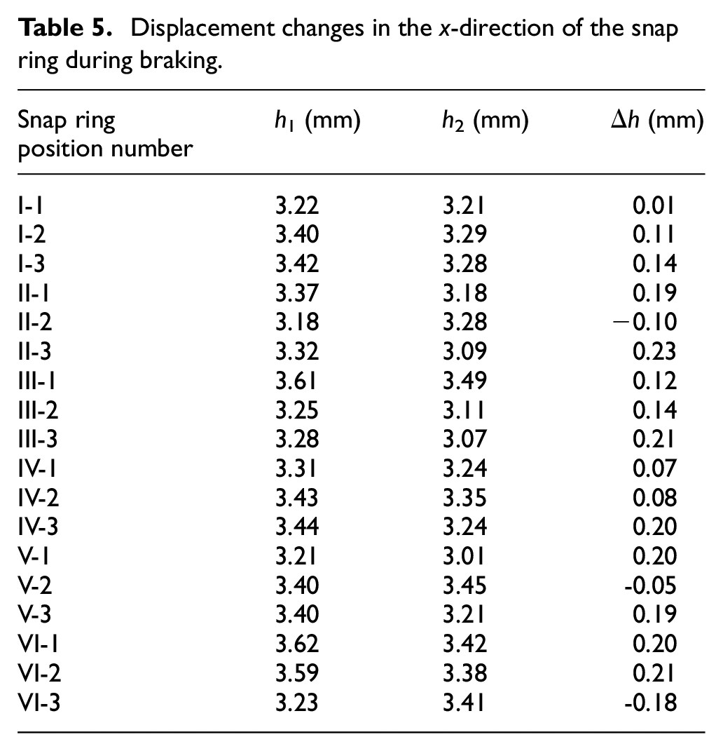
A cloud chart showing the change in height at various snap ring locations is shown in Figure 13. Three snap rings form a group. together. When there is a positive height difference, the snap ring’s final height is lower than its starting height. There is less force applied to the snap ring by the component. When the height difference is negative, it means that the component is applying more force to the snap ring. The results show that the majority of the changes in the snap ring’s height difference are positive, which suggests that the majority of the forces applied to the snap ring by the components during the braking process tend to decrease.
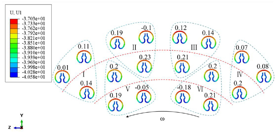
Cloud diagram of the displacement results of the snap ring in the x-direction.
The positive and negative changes in the height of the snap ring represent the increase or decrease in the force exerted by the component on the snap ring. Since the displacement change of the snap ring during the braking process is the main focus of this research and analysis, the absolute value change is taken into consideration when analysing the snap ring displacement change results.
Analysis of snap ring x-direction displacement results:
(1) The snap rings are divided into six groups. The average displacement change in the x-direction of each group of snap rings is calculated. Group VI snap rings have an average displacement shift in the x-direction of 0.1967 mm, with the highest change.
(2) Snap rings in the speed entrance area have an average x-direction displacement change of 0.1567 mm, in the transition area, the average x-direction displacement change is 0.1417 mm, and in the speed exit area, the average x-direction displacement change is 0.1167 mm.
(3) The inner ring snap ring’s average x-direction displacement change is 0.1575 mm, and the middle ring snap ring’s average x-direction displacement change is 0.1733 mm, the outer ring snap ring’s average x-direction displacement change is 0.1025 mm.
The snap ring is displaced in the x direction when the heat generated during braking generates unstable contact between components. The findings show that the snap ring’s x-direction displacement in the brake disc’s inner ring, middle ring and speed inlet area is very visible. This is due to the fact that the brake components in the speed entrance area make contact with the ground first, move quickly, and have a greater impact on the snap ring from surrounding components than they do in the speed exit area. The brake piston is located close to the inner and middle rings of the brake disc. The maximum temperature band on the disc surface moves inward as the braking time increases, as the brake disc temperature findings demonstrate. Temperature increases have an impact on the brake pad components, as does a decline in contact performance and displacement movement between them. As a result, the snap ring’s x-direction displacement varies dramatically and its balance is impacted at this position.
Z-direction displacement change of snap ring
Z-direction displacement phenomenon of snap ring
Through the clamping component, the snap ring accomplishes its goal of regulating the positioning of its movement range. The z-direction displacement of the snap ring, meaning the snap ring’s opening distance, will vary as a result of displacement changes and component impacts during the braking process. The degree of expansion of the snap ring is amplified ten times due to the modest quantity of change. The displacement cloud diagrams of the snap ring at the beginning and end of the process are displayed in Figure 14. By calculating the difference between the displacement values of two symmetrical places at the snap ring opening end, the distance of the snap ring opening is found. The snap ring’s opening distance at this point is d1, and it will be d2 at the end of the time. It is specified that when Δd = d2-d1, Δd > 0, the snap ring expands while braking, and when Δd < 0, the retraction will occur.

Displacement changes in the z-direction of the snap ring.
Causes of z-direction displacement of snap ring
The disc brake’s operation relies on the frictional contact between the brake disc and friction body to produce braking force. Each component will exhibit a fairly noticeable displacement along the tangential direction of the brake disc rotation, that is, in the z-direction, following the conversion of static friction into sliding friction. The fastener snap ring will be negatively impacted by this and will be shifted in the z-direction.
The support positioning seat’s z-direction displacement cloud diagram may be shown in Figure 15. The support placement base exhibits an anticlockwise rotation tendency, as can be observed in the image. The support positioning seat serves as a pivot component. The friction body will deflect as a result of the support positioning seat’s displacement in the z-direction. The snap ring’s equilibrium state will be harmed by component displacement, as seen in Figure 16, and the snap ring’s displacement in the z-direction will alter.

Z-direction displacement cloud diagram of the support positioning base.

Effect of friction body displacement on snap ring service.
Z-direction displacement results of snap ring
The opening variations of the 18 snap rings during the braking process are displayed in mm, as indicated in Table 6. The change in the snap ring’s opening end during the braking process is equal to Δd = d2-d1, which is the snap ring’s opening distance at the end time minus the opening distance at the beginning time. The snap ring’s displacement shift in the z-direction during braking is represented by Δd.
Displacement changes in the z-direction of the snap ring during braking.

The z-direction displacement change cloud diagram for each snap ring at various places is displayed in Figure 17. Three snap rings form a group. The snap ring opening distance at the end time is subtracted from the snap ring opening distance at the beginning time to determine the opening change. The results demonstrate that all of the opening changes are positive, indicating that every snap ring exhibits an expansion tendency when the brakes are applied.

Cloud diagram of the displacement results of the snap ring in the z-direction.
Analysis of the displacement results of the snap ring in the z-direction:
(1) The snap rings are divided into six groups. The average displacement change in the x-direction of each group of snap rings is calculated. Group VI snap rings have an average displacement shift in the z-direction of 0.1233 mm, with the highest change.
(2) Snap rings in the speed entrance area have an average z-direction displacement change of 0.1083 mm, in the transition area, the average z-direction displacement change is 0.0733 mm, and in the speed exit area, the average z-direction displacement change is 0.0983 mm.
(3) The inner ring snap ring’s average z-direction displacement change is 0.1575 mm, and the middle ring snap ring’s average z-direction displacement change is 0.0833 mm, the outer ring snap ring’s average z-direction displacement change is 0.0678 mm.
Based on the snap ring’s z-direction displacement change findings, it is discovered that the displacement change’s obvious position matches the snap ring’s x-direction displacement result. In extreme circumstances, the snap ring may fail due to reduced tightening performance caused by displacement beyond a predetermined value. In real brake pad repair, these positions’ snap rings frequently fail. The basis for researching snap ring failure is laid by the snap ring displacement data, which shows the locations of the snap ring that are vulnerable to failure.
Changes in the stress of snap ring
Results of change in contact stress of snap ring
As a fastening element, the snap ring plays a clamping and positioning role in the brake pad and is in close contact with the component. There is reciprocal displacement between components during the braking process, as well as variations in motion. Because of component interaction, there will be a concentration of stress. Fatigue failure of fasteners will result from prolonged concentration of stress. As a result, analysis of the snap ring’s contact stress results is required.
The distribution of contact stress at the end of snap ring braking is depicted in Figure 18. It can be seen from the stress cloud diagram of the snap ring that the stress concentration flash points are mainly concentrated at the front end and middle arc position of the snap ring. The contact between the pressure block and the snap ring during tooling in the preceding analytical phase is what causes the stress concentration flash point at the front end of the snap ring, which is consistent with the snap ring tooling results. The stress concentration flash point appears in the middle arc of the snap ring because it is in contact with the pin of the friction body. During the braking process, the snap ring and the friction body will have an interaction force. The contact surfaces rub against each other, and stress concentration occurs in the snap ring.
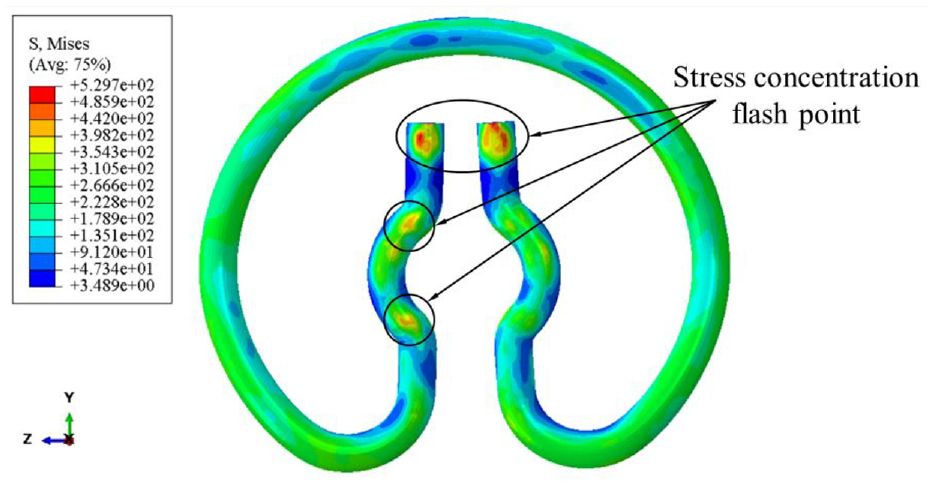
Contact stress cloud diagram of snap ring.
The maximum contact stress values at the beginning and end moments of the 18 snap rings and changes are displayed in Table 7.
Maximum contact stress value amount at the initial and end moments of the snap ring and change.

The contact stress cloud diagram and the maximum contact stress change at the end of the 18 snap rings are displayed in Figure 19.

Contact stress distribution cloud diagram and variation of snap ring.
The positive and negative changes in the contact stress of the snap ring represent the increase or decrease in the maximum contact stress of the snap ring. Since the focus of this research and analysis is on the stress change during the snap ring’s braking process, the absolute value is taken into consideration when analysing the results of the change in contact stress of the snap ring.
Analysis of snap ring contact stress results:
(1) The snap rings are divided into six groups. An average is computed for the maximum contact stress change for every set of snap rings. Group VI snap rings had the biggest change in maximum contact stress, with an average of 9.8 MPa.
(2) The snap ring’s average maximum contact stress change in the speed inlet zone is 5.1 MPa, while the average maximum contact stress change in the transition zone is 0.5 MPa and the average maximum contact stress change in the speed exit zone is 3.1 MPa.
(3) The inner ring snap ring’s average maximum contact stress change is 5.4 MPa, the middle ring snap ring’s average maximum contact stress change is 4.4 MPa, and the outer ring snap ring’s average maximum contact stress change is 0.5 MPa.
Stress variations are also influenced by the movement of the brake pad’s component parts. The inner ring of the brake disc and the speed entrance area of the snap ring experience substantial fluctuations in contact stress, suggesting that the contact between the snap ring and the components in these areas is relatively harsh.
Result of internal stress change of snap ring
The snap ring is an elastic element that relies on its own structural characteristics to convert elastic potential energy into mechanical energy. It is in a state of deformation during the entire service process. There are areas of stress concentration inside it. Long-term stress concentration will lead to fatigue damage to the internal structure. Therefore, it is necessary to analyse the internal stress distribution of the snap ring and obtain the changing trend of the internal stress of the snap ring at different positions.
As can be seen in Figure 20, the snap ring’s service height is h. To produce the snap ring’s stress profile cloud diagram, a section with a height of h/2 is constructed on the y-z plane. The snap ring’s internal stress cloud diagram is displayed in Figure 21. The snap ring’s internal stress cloud diagram illustrates that the snap ring’s maximum internal stress is primarily concentrated in the snap ring structure’s bending area. This is due to the snap ring’s constant expansion and tightness, which serves to tighten the friction body. Furthermore, it is also very evident where the stress is at the point of contact between the friction body pin and the snap ring. This is a result of the snap ring’s constant contact with the pin portion, which is similar to the snap ring’s contact stress result.

Schematic diagram of the position of the snap ring cross-section.

Internal stress cloud diagram of the snap ring.
The maximum internal stress values at the beginning and end moments of the 18 snap rings and changes are displayed in Table 8.
Maximum stress value amount inside the snap ring at the initial and final moments and change.

The internal stress cloud diagram and the maximum internal stress value change at the conclusion of 18 snap rings are displayed in Figure 22.

Cloud diagram and variation of stress distribution inside snap ring.
The positive and negative changes in the internal stress of the snap ring represent the increase or decrease in the maximum internal stress of the snap ring. Since the focus of this research and analysis is on the stress change during the snap ring’s braking process, the absolute value is taken into consideration when analysing the results of the change in internal stress of the snap ring.
Analysis of internal stress results of snap ring:
(1) The snap rings have been divided into six groups. The average maximum stress change inside each group of snap rings is calculated. Group VI’s snap rings have the largest average maximum stress change, at 15.5 MPa.
(2) The average maximum stress change inside the snap ring in the speed inlet zone is 15.1 MPa, the average maximum stress change inside the snap ring in the transition zone is 12.7 MPa, and the average maximum stress change inside the snap ring in the speed exit zone is 10.8 MPa.
(3) The average maximum stress change inside the inner ring snap ring is 19.0 MPa, the average maximum stress change inside the middle ring snap ring is 7.4 MPa, and the average maximum stress change inside the outer ring snap ring is 13.9 MPa.
The contact stress change and the internal stress change of the snap ring are clearly located in the same place. Long-term stress concentration will lead to fatigue, which will cause the snap ring to fail, whether it is from internal or exterior contact stress. In order to investigate the failure of the snap ring and provide the groundwork for future research, it is imperative to analyse the stress findings of the snap ring.
Conclusions
This paper establishes a brake pad/disc brake finite element model to simulate the braking process of high-speed trains. With an emphasis on fastener snap ring service behaviour during braking, alterations in snap ring service behaviour are examined and described in terms of displacements and stresses. The following conclusions are reached.
(1) Braking to 4.05s, the brake disc appeared to have a maximum temperature of 73.34°C, located on the outside of the disc. As braking time increases, the highest temperature band moves inward and is located on the inside of the brake disc when braking to 7.425 s. At the end of braking, the temperature of the disc surface is distributed in a sheet-like manner, which is a manifestation of the heat dissipation of the brake disc. Throughout the braking process, the maximum temperature on the surface of the brake disc showed a trend of increasing and then decreasing.
(2) During braking, the contact performance of the friction interface deteriorates under the influence of high heat and friction torque. In order to ensure a tight fit between the friction body and the brake disc for maximum braking performance, the support positioning seat and the friction body is adjusted by means of a floating structure. The movement of the brake brake pad components has an effect on the service performance of the fastener snap rings, which change in displacement and stress.
(3) In the velocity entrance area, the snap ring displacement and stress changes are always larger than in the velocity exit area. The inner and middle ring snap rings of the brake pad have larger displacement changes than the outer ring snap rings, and the inner ring snap rings have larger stress changes than the middle and outer ring snap rings. Group VI snap rings that are located inside the brake pad and in close proximity to the speed inlet area exhibit the most noticeable displacement and stress variations. In the x and z directions, the average displacement changes are 0.1967 and 0.1233 mm, respectively. The average changes in contact stress and internal stress are 9.8 and 15.5 MPa.
This research derives and compares the changes in the displacement and stress of the snap ring at each position, taking into account the impact of the thermal-mechanical coupling field on the service behaviour of the snap ring during the braking process. Better research on the failure of snap rings can be conducted on the basis of the comparison results. However, the braking process not only includes the coupling of these two physical fields, but also physical quantities such as vibration and wear. But in addition to the coupling of thermal-mechanical physical fields, physical quantities like wear and vibration are also involved in the braking process. These consequences on the service performance of the snap ring have gone ignored. More physical quantities can be taken into consideration in the study to better analyse the changes in the service behaviour of the snap ring.
Footnotes
Appendix
Handling Editor: Sharmili Pandian
Author contributions
All authors contributed to the study’s conception and design. The idea building of this work is done by J. Y. and Z. Z., the simulation is done by Z. Z. and L. S., the data management is Z. W. and Z. L., the original draft writing is Z. Z. and the article review is Y. L. and Z. S. All authors commented on previous versions of the manuscript. All authors read and approved the final manuscript.
Declaration of conflicting interests
The author(s) declared no potential conflicts of interest with respect to the research, authorship, and/or publication of this article.
Funding
The author(s) disclosed receipt of the following financial support for the research, authorship, and/or publication of this article: This study was funded by the National Natural Science Foundation of China: 52375169, Liaoning Provincial Science and Technology Program: No. 2022JH2/101300228, Liaoning Provincial Doctoral Research Foundation Project: No. 2022-BS-260, Liaoning Provincial Department of Education Scientific Research Project: LJKZ0479, Liaoning Provincial Department of Transport Research Project: No. 202148.
Data availability statements
The data that support the findings of this study are not openly available due to reasons of sensitivity and are available from the corresponding author upon reasonable request.