
Abstract
To accurately explore the numerical vibration response and heat transfer characteristics of heat exchanger with fluid-solid coupling in the actual working environment. According to the finite volume method and Euler-Lagrange method, the three-dimensional model and mathematical model of coupled vibration are founded. The 0.5 m/s working condition is taken as the experimental object to verify the rationality of the coupling calculation model. Then, bidirectional and unidirectional fluid-solid coupling simulation methods are chosen to resolve the vibration acceleration and heat transfer characteristics of heat exchange tubes at different speeds, and the effects of the two methods on the vibration response of heat exchange tubes are contrasted. Results indicate that under bidirectional coupling, the heat transfer characteristics of the heat exchange tube will experience significant fluctuations due to the vibration of the tube bundle. The shell-side domain has more prominent influence on the vibration of the heat exchange tube when the water velocity is greater than 0.5 m/s. Typical digital features of vibration acceleration and vibration frequency are improved by 110.03%–140.47% and 99.71%–99.88% respectively. The research not only provides a valid analysis approach for fluid-solid coupling vibration of heat exchanger, but also gives theoretical guidance to its vibration optimization design.
Keywords
Introduction
Due to the widespread application and important role of heat exchangers in various industrial scenarios, people have increasingly high requirements for heat exchanger capacity and recycling in high energy consuming industries. In addition, with the increasing requirements for the safety property and thermal transfer efficiency of heat exchangers, researchers are paying increasing attention to the lateral vibration of heat exchangers. In industrial production, the shell side domain of heat exchanger design is usually closed and limited. When a heat exchanger operates under different operating conditions, the flow field around it has undergone drastic changes. These changes cause deformation in the solid domain where the heat exchange tube is located, thereby exacerbating the lateral vibration of the heat exchange tube. Therefore, as the fluid operating speed increases, the interactive coupling effect between the shell side drainage basin and the heat exchange tube would become increasingly important. The lateral vibration of heat exchange tubes (HETs) not only damages some major components of the system and reduces the lifespan of a heat exchanger, but also seriously affects the safety and stability of the heat exchanger device.1,2 Thus, the fluid-structure interaction transverse vibration response mechanism of the heat exchanger in the real operating environment is explored.
In addition, domestic and foreign scholars have achieved certain results in the research of the transverse vibration characteristics of heat exchange tubes. Su et al. 3 proposed a new type of elastic heat transfer element based on the idea of fully utilizing fluid induced lateral vibration to enhance heat transfer; at the same time, the uneven fluid impact excitation affecting the transverse vibration of the heat exchange tube is transformed into the Contact force between the fluid domain structures, and the transverse vibration dynamic model of the heat exchanger is established. Lai et al. 4 studied the influence of periodic fluid forces on flow induced vibration of tube bundles in a rotating triangular tube array; based on the theory of solid dynamics, a dynamic model of tube bundle vibration under the influence of periodic fluid force and gap limitation was established, and numerical simulation calculations were conducted using periodic fluid force as the disturbance source. Ding et al. 5 explored the vibration between cylindrical tubes at different staggered positions, and established the transverse vibration model of coupling between the drainage basin and the solid domain. At the same time, the effects of various parameters; for instance, the distance between heat exchange tubes and the cross angle on the dynamic characteristics of the fluid solid coupling surface is studied. Then, the influence of near wake structure and temperature distribution on the transverse vibration of heat exchange tubes is analyzed. Zhang et al. 6 utilized the fluid kinetic energy caused by flow induced vibration, based on the unsteady RANS method and the Spalart-Allmaras turbulence model, combined with dynamic grid technology, to determine the separation characteristics of vortex induced vibration galloping coupling and the average response of composite random vibration of heat exchange tubes. Finally, the influence of parameter changes and system natural frequency on lateral vibration response was analyzed.
With the continuous improvement of water flow velocity in the fluid field of heat exchanger, the flow field and flow characteristics in the fluid field of the heat exchanger have undergone significant changes, making a larger number of complicated and grave flow problems in the heat exchanger more prominent. Meanwhile, the drastic changes in the flow field also exacerbate the lateral vibration response of the heat exchange tube in the heat exchanger. So, considering only the self-motivation interference of the solid domain within the heat exchanger system, the related scholars are unable to exactly describe the time-domain response of lateral vibration during the operation of the heat exchanger in actual environments. Researchers have begun to delve deeper into the flow field characteristics inside heat exchangers and the lateral vibration characteristics under fluid flow disturbances. Yakut and Sahin
7
measured and recorded the amplitude and vortex shedding frequency changes along the axis under different pitch sizes of heat exchange tubes through flow induced vibration characteristics testing experiments in conical ring heat exchangers. They analyzed the influence of different heat exchange tube structural parameters on fluid flow characteristics. Wu et al.
8
used ANSYS FLUENT software to construct a three-dimensional model of the heat exchange tube and flow field domain, and solved the motion of the heat exchange tube based on dynamic grid theory. Then, the variation process of the shell side flow field was described using pressure fluctuations and pipeline vibration, and the influence of pipeline vibration on the flow field under various flow velocities was analyzed. Anantharamu and Mahesh
9
simulated the three-dimensional turbulence in the shell side of rectangular tube bundles at different Reynolds number through the steady incompressible Navier Stokes Equation. The simulation analyzed that the interaction between fluid and structure is unidirectional coupling, and expounded the dynamic characteristics of water flow in the shell side flow field. Carrillo Segura et al.
10
constructed a three-dimensional vibration dynamic model of the interaction between an elastic tube plate and surrounding fluid, and proposed an accurate three-dimensional solution to solve the free vibration problem between the fluid and a simple support plate. Liu et al.
11
studied the water flow vibration response caused by lifting pipe bundles for mining ore under seawater. A nonlinear vibration control model of pipe bundles coupled in multiple flow fields under seawater mining was set up using finite element numerical simulation. At the same time, the longitudinal transverse coupling effect was considered to make use of element method, energy method, and Hamiltonian variational principle. The
To increase the heat transfer effect and service life of the heat exchanger, Delgado et al. 12 and Salinas-Vázquez et al. 13 used the heat exchange tubes with different parameters and establish a fluid-structure interaction vibration dynamic model when exploring the lateral vibration response of the heat exchange tubes under fluid disturbance. Only the unidirectional effect of fluid perpendicular to the tube bundle on lateral vibration is considered. However, in the actual operating environment of the heat exchanger, there is a bidirectional coupling effect between the transverse fluid and the heat exchange tube. Currently, many scholars are conducting research on the fluid-structure interaction of fluid and solid in the fields of ocean, natural gas, petrochemical industry, et al; for example, the hydrodynamic effect and fluid-structure interaction vibration of underwater tail fins driven by composite materials, the gas-solid flow characteristics in inclined tubes, the interaction vibration of fluid and solid in cylindrical shells based on energy method, etc.14–16 However, currently the majority of scholars have not conducted research on the bidirectional fluid structure coupling lateral vibration control of the fluid in elastic heat exchangers. The operation of an elastic structure heat exchanger can be simplified into the fluid domain and the solid domain of the heat exchange tube, and its various operating characteristics are similar to the state of the solid at different wind speeds. Numerous researchers have conducted relatively mature research on the dynamic characteristics of gas-solid coupling.17–20 Therefore, this paper draws lessons from the related research in the domain of air-solid coupled, and combines the characteristics of the elastic structure heat exchanger, proposes a suitable fluid-structure interaction vibration calculation method.
Heat exchanger raises the vibration of the elastic tube through fluctuating fluid, thereby improving the heat transfer efficiency of the heat exchanger. Currently, there are relatively few literatures about fluid vibration enhancing heat transfer in elastic tubes. However, the structure of the traditional elastic tube bundle makes the heat exchange area per unit volume smaller, the comprehensive heat transfer performance is lower, and the energy utilization efficiency of the heat transfer performance of the tube bundle is lower, resulting in poor overall efficiency of the heat exchanger, so it is urgent to optimize and popularize it. According to the flow conditions inside the heat exchanger, the influence of the tube bundle on the shell side condition is much greater than that on the tube side condition. Firstly, this paper addresses the problems in the study of fluid-solid coupling characteristics in the actual operating environment of heat exchangers. The mathematical model and calculation model of coupled vibration of flow field and heat exchange tube were established based on the consideration of fluid-structure interaction. Meanwhile, the numerical calculation results of this article were validated with experimental results from publicly available literature. Two solving methods were adopted sequentially to iteratively resolve different computational domains, and the flow load (impact force of water flow) and vibration acceleration of heat exchange tubes under different working conditions were obtained. At the same time, the influence of coupling phenomena of heat exchange tubes under different flow fields on their vibration response was analyzed. Finally, according to the calculated numerical results, a quantitative analysis was conducted on the heat transfer enhancement characteristics under shell-side conditions, and the heat transfer performance of the elastic tube bundle was discussed using the Performance Evaluation Criteria (PEC).
A framework of this study is as follows: The second part mainly focuses on numerical calculation methods, including geometric calculation models, flow field control, grid settings and boundary conditions, as well as verification of grid independence; By comparing the experimental results with similar literature, the correctness of the mathematical model and calculation method was verified.
Models and numerical methods
Mathematical model
Flow field control equation
When the fluid flows fully in the heat exchanger, the flow field around the heat exchange tube presents an incompressible flow state of high Reynolds number, so it can be considered that the flow field in the shell side is a three-dimensional, viscous, incompressible unsteady turbulent flow field. The numerical calculation mathematical model in this paper is based on the following assumptions21,22 and simplifications:
(1) The working medium is an incompressible Newtonian fluid;
(2) Neglecting the coupling effect between the vibrating wall and the fluid;
(3) The heat loss generated by viscous dissipation during fluid flow is negligible;
(4) The floating force caused by the density difference and gravity of the fluid is ignored;
The motion of pipe wall vibration is harmonic motion, and its motion parameters depend on the amplitude and frequency of wall motion.
Moreover, taking into consideration the pipe wall boundary of the vibration velocity flow field in this study, on the basis of two methods (finite volume method and Euler method) and two equations model (standard

where
In real life, when the heat exchanger is working, its structural components will not only improve the amount of work of simulation model, but also reduce the universality of simulation results. Due to the data of fluid-solid coupling in this paper were processed at the junction of fluid solid surfaces, the physical model of the actual operating environment of the heat exchanger was further simplified as follows:
(1) The heat exchange tube was seen as a relatively regular “hollow” thin-walled tube, neglecting the internal and external connection components of heat exchange tubes.
(2) Due to the long shell side of the heat exchanger, the fluid has a relatively small impact on the tube at the end of the shell side. So, the influence of the end of the heat exchange tube on the uniform velocity section can be ignored.
(3) In this paper, the influence of changes in physical properties was ignored, and the energy loss both the heat exchanger and the working environment was ignored.
Based on the above assumptions, the flow field control equation for this study is as follows:
Mass conservation equation:

where
Momentum conservation equation:


where
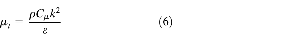
Considering that the vibration of the tube bundle can generate vortex streets, using the

where

By coupling equations (4) and (5), the following equation can be obtained:
where
The above equations were solved using simulation software ANSYS FLUENT 2021. R1 CFD. SIMPLE algorithm is selected to deal with the coupling problem of boundary pressure and water velocity in flow field. During the whole of simulation process, monitoring the residual of each operating equation and setting the convergence criteria for all variables to

Three-dimensional geometric modeling of heat exchanger.
Parameters of geometric modeling.

Grid setting and boundary conditions
This paper used MESH CFD (ANSYS MESH CFD version 2021. R1) to grid the flow field inside the shell side. In simple to even better catch the flow field changes of heat exchange tubes and enhance the interconnection computing efficiency. Boundary layer is put up on the heat exchanger shell wall and tube wall, and grid refinement treatment should also be used here. Due to the flow distribution is relatively simple at a distance from the surface of the solid domain, it is necessary to divide the mesh here more roughly. Furthermore, to assure that the mesh density does not have a marked influence on the simulation results, this paper determined the height of mesh near the shell wall and tube wall, and set various mesh sizes and quantities to divide according to the same growth rate. Taking into account the complexity of exchanger shell, a tetrahedral mesh is used for modeling. As the structure of heat exchange tube was comparatively simple, it is mainly established by hexahedron mesh. According to Figure 2, there are eight layers of boundary layer grids near the wall of the heat exchange tube. According to this study, the standard

Grid division and boundary conditions: (a) shell side, (b) heat exchange tube.

Verification of grid independence.
In computer simulation, the parameters are set as follows:
(1) The inlet of shell-side fluid: water flow velocity
(2) Fluid outlet pressure:
(3) Coupling interface: wall temperature
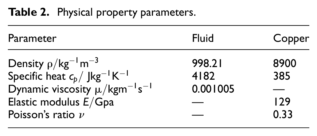
In this study, the heat exchange tube was made of red copper, and its specific parameters are shown in Table 2.
Physical property parameters.
This paper takes the tube in the heat exchanger as the simulation object during the time period from start to stable operation. Inspired by the wind tunnel experiment, the heat exchange tube is in a stationary state in the heat exchanger shell, and the water flow can flow to the heat exchange tube at different water flow velocities. Not only does this method affect the respective positions of water flow and pipe wall, but also the influence between water flow and pipe wall is not significant. Besides, the parameters in each domain of the simulation are shown in Figure 2. At the bottom of the heat exchanger shell, there is a velocity inlet, at the top, there is a pressure outlet, and the wall of the heat exchanger shell is an adiabatic and anti-skid moving wall. This paper selects four operating conditions:
Solid motion equation
In this paper, the fluid-solid coupling calculation follows the conservation law, and the position of the contact surface between fluid and solid realizes the equality or conservation of parameters such as force, displacement, heat flow and temperature, with the following relationship:
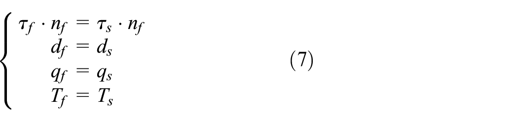
where
During the fluid-solid coupling vibration between shell and pipe wall, due to the problem of energy loss on the fluid-solid interface, the wave equation of fluid-solid coupling whole is as follows:

For the solid motion, the comprehensive motion analysis of the tube wall is carried out through the arbitrary Euler theory. Heat exchange tubes vibrates under the flow fluid working medium, and after discretization treatment, the dynamic balance expression is as follows:

By combining equations (8) and (9), the following discretization expression of fluid-solid coupling whole can be obtained:

In the formula,
Model calculation and analysis method
This paper mainly studies the coupling effect between fluid and heat exchange tube in a heat exchanger. In simple to more accurately calculate the true coupling between the fluid and solid domains in the heat exchanger, this paper adopts a bidirectional coupling analysis method. This method simultaneously solves the fluid domain control equation in the heat exchanger and the transient equation of coupled vibration in the solid domain of heat exchange tubes. It considers the real-time interaction between the fluid flow in the heat exchanger and the vibration posture change of the heat exchange tube. The heat exchange tube is constantly in different vibration posture changes, and different vibration postures correspond to different fluid loads on the heat exchange tube, different fluid loads will react on the heat exchange tube and disturb its vibration posture. The specific bidirectional coupling analysis method flow is shown in Figure 4.

Flow chart of bidirectional coupling analysis method.
In the simulation calculation of this paper, in each time step, data exchange and iteration were carried out between the heat exchanger flow field calculation domain and the heat exchanger pipe calculation domain. Using the interpolation algorithm of coupling module to finish data conversion of fluid impact force and deformation displacement at nodes, and using the bidirectional coupling method to quantity the coupling effect of fluid and solid in the actual operating environment of the heat exchanger. According to Figure 5, the iterative coupling starts at a certain time point
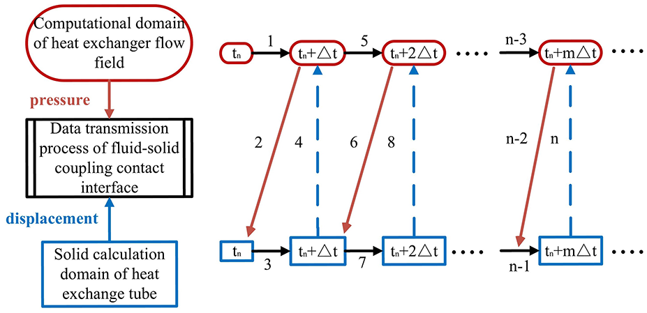
Bidirectional coupling interaction iterative calculation process.
Verification of calculation results
For verifying and testing the accuracy and reliability of the numerical method proposed in this paper, the numerical results were compared with those in relevant literature.21,22 The mathematical model with the same parameters was established based on the cone spiral tube bundle vibration test bench in reference 21 and the single row elastic tube bundle vibration test bench in reference. 22 During the experiment, the acceleration amplitude and vibration frequency at diverse inlet flow rates were measured by an acceleration sensor. Adopting the grid setting and numerical simulation method described in this article, the experimental results were used to compare with the numerical results, as shown in Figure 6(a) and (b). From the following two figures, it can be seen that the numerical results are basically consistent with the experimental results in relevant literature. The maximum relative error between the numerical results and the experimental results is 5.79%, which meets the requirements for subsequent vibration calculation analysis in this paper.

Comparison chart of simulation results and experimental results under different flow velocities: (a) comparison chart of simulation results and experimental results of frequencies at different flow rates, (b) comparison between simulation results and experimental results of acceleration amplitude at different flow velocities.
Based on the numerical calculation method of this study and using the same physical parameters, the numerical results were compared with the experimental results in reference. 25 The elastic tube model constructed in this paper is the same as the heat transfer tube used in the experiment in reference 25 in terms of tube structure size, material, and fluid flow. Using the numerical calculation method and geometric model in this article, the heat transfer of shell side water flow velocity in the range of 0.019–0.136 m3/s was simulated. According to reference, 25 different Nu values can be obtained at different Reynolds numbers Re, and are shown in Figure 7(a) with a 10% error bar. The error between the Nu gained from numerical simulation and experimental data is within the range of 3.48%–8.42%. These errors all originate from the simplification of measurement and geometric models, which ensures the accuracy of numerical results and lays the foundation for the follow-up. Moreover, this paper also compared it with the simulation in reference. 26 Parameters that are the same as those in reference 26 are adopted to simulate various working conditions. The average heat transfer coefficient of tube bundles with different Reynolds numbers is calculated and compared with the numerical results in reference, 26 as shown in Figure 7(b). Comparing with the simulation results in this paper, the numerical results in the literature are represented by a 10% error bar. The error of the heat transfer coefficient is within the range of 3.48%–8.42%, which further shows that the numerical calculation method in this paper can meet the subsequent analysis of heat transfer data.

Comparison of heat transfer numerical calculation results: (a) comparison chart with experimental results, (b) comparison chart with simulation results.
Results and discussion
Flow field response of heat exchange tube vibration
For understanding the vibration characteristics of heat exchange tubes, the shell side drainage basin is first analyzed. Figure 8 shows the velocity vector diagram of the shell side at an inlet velocity of 0.5 m/s. At this point, the fluid flow inside the shell has reached a stable state and the flow field has fully developed. In Figure 8(a) and (b), the fluid flows around the heat exchange tube, leading to a great deal of vortices in the gap between adjacent tube spacing. Moreover, for the bottom of the heat exchange tube, it is more susceptible to fluid impact. According to Figure 8(a1)–(a5), it can be seen that after the fluid enters the shell of the heat exchanger, the water flow will impact the inner wall of the shell, and then the direction of the water flow will change, causing the water flow to impact the inner cavity of the heat exchanger shell again. Due to the reflux phenomenon of the fluid, a large number of eddies will be generated. As we know, the fluid flow impacting the tube bundle and the inner wall will produce vortex, and the vortex has a certain scouring effect on its surface, which not only reduces the thickness of the Boundary layer of the velocity field on the outer surface of the tube wall, but also improves the vibration effect of the tube.

Shell side velocity vector diagram: (a) z = 0, (b) y = 0. (a1) x = 22.5, (a2) x = 67.5, (a3) x = 112.5, (a4) x = 157.5, (a5) x = 202.5.
Time domain response of heat exchange tube vibration
When the heat exchanger operates in a real environment, it will generate forward and backward vibrations and lateral vibrations in the vertical and parallel directions to the heat exchange tube. From the previous study, the vertical vibration of heat transfer tube bundles is not only similar to the up-and-down vibration in the dynamic model, but also close to their inherent properties.27,28 According to Section “Flow field response of heat exchange tube vibration” of this paper, we know that due to the asymmetric arrangement of the heat exchange tube structure at the axis, asymmetric flow loads are generated when subjected to fluid action, making it easier to exacerbate the lateral vibration of the heat exchange tube. Therefore, this section simulates the transverse vibration acceleration of the solid region of the heat exchange tube under four diverse working conditions: single direction coupling, two-way coupling and without other fluid disturbance (only the frequency disturbance of the heat exchange tube itself). The results are shown in Figures 9–Figures 12. The typical numerical characteristics of lateral vibration acceleration are taken as root mean square, mean, minimum, and maximum values. Table 3 shows that the typical values without other fluid disturbances are taken as evaluation indicators or comparative analysis of coupled vibration effects. During this paper, the calculated lateral vibration acceleration refers to the up-and-down vibration.

Time domain response of vibration displacement in the x, y, and z directions of the heat exchange tube: (a) x-direction, (b) y-direction, (c) z-direction.
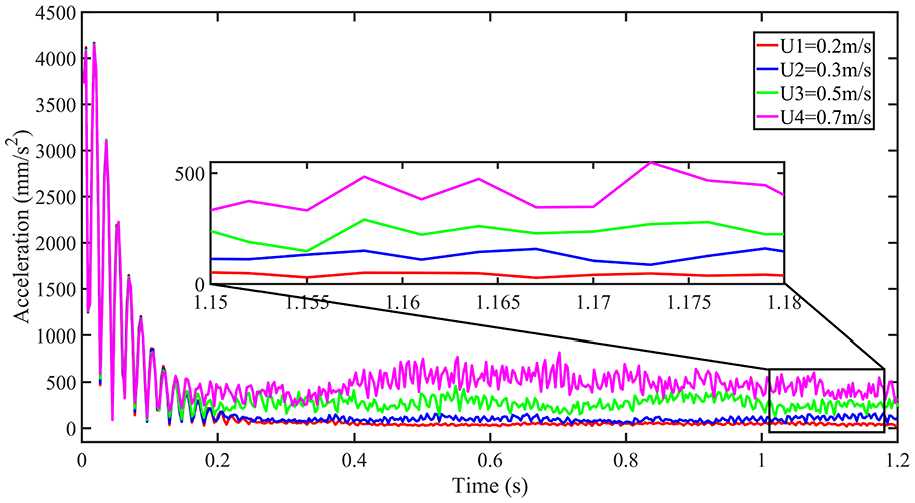
Time domain response of vibration acceleration of the heat exchange tube.

Frequency domain response of vibration acceleration of the heat exchange tube.

Horizontal vibration response of heat exchange tube: (a) 0.2 m/s, (b) 0.3 m/s, (c) 0.5 m/s, (d) 0.7 m/s.
Comparison of the representative numerical features of the vibration acceleration under different velocity conditions.

From Figure 10 and Table 3, we can see that in relative to the horizontal vibration velocity which ignores the fluid disturbance, when the water velocity is less than 0.5 m/s, the representative numerical features of one-way coupling and two-way coupling have varied by 65.13%–92.97% and 92.57%–94.33% separately, and the vibration amplitude has also changed by 93.95%–100.21% and 93.93% respectively. By combining the time-domain response diagrams of the heat exchange tube in different directions again, we can see that when the water velocity is less than 0.5 m/s, the fluctuation caused by the fluid load on the heat exchange tube and itself vibration is relatively small. Thus, the interconnection influence between the fluid and the heat exchange tube has a reversely weak impact on vibrations in different directions, while the self-excitation of the heat exchange tube is the main source of disturbance.
Combined with Figures 11 and 12, we can see that when the water flow velocity is greater than 0.5 m/s, the difference in water pressure characteristics around the heat exchange tube becomes increasingly significant as the water flow velocity in the shell side increases. Combined with Figure 9, it can be seen that when the water flow velocity is greater than 0.5 m/s, as the water flow velocity on the shell side increases, the difference in water flow pressure characteristics around the heat exchange tube becomes greatly obvious. This causes a corresponding increase in the flow load on the heat exchange tube, and the horizontal vibration response of the heat exchange tube ultimately increases. In addition, from Table 3, we can see that when the water velocity is not less than 0.5 m/s, the representative numerical features of one-way coupling and two-way coupling have improved to 102.57%–134.67% and 110.03%–140.47%, and the vibration amplitude has also increased by 99.74%–99.94% and 99.71%–99.88%, respectively. According to Figure 12(a)–(d), we can see that at each iteration time step, compared with the one-way coupling between the shell side and the water flowing outside the heat exchange tube, the horizontal vibration acceleration under the two-way coupling is obviously increased, and it is more prominent with the increase of water velocity. From Figures 9 to 10, it can be seen that in each iteration time step, the fluid on both sides of the heat exchange tube is more asynchronous because the moving state of the heat exchange tube changes the flow field around it, which leads to significant fluctuations in the “equilibrium” flow load. In addition, fluctuating flow loads and external random excitations also play a role, ultimately leading to a significant increase in the horizontal vibration acceleration of the heat exchange tube, making the structural safety of the heat exchanger more important.
Frequency domain characteristics of heat exchange tube vibration
The research takes into account the idea of normalizing random variables, which transforms the horizontal vibration acceleration signal of heat exchange tubes randomly distributed in time domain into the vibration acceleration power density spectrum in frequency domain. According to Figure 13, this paper not only discussed the change rule of transvers random vibration of heat exchange tubes, but also gained the frequency domain distribution of random vibration of heat exchange tubes under one-way coupling, two-way coupling, and no other interference factors. For more clearly comparing the influence of “one-way coupling, two-way coupling, and no other interference factors” on the transvers vibration of heat exchange tubes, the linear scale of the maximum amplitude of transvers vibration acceleration in the frequency domain is transformed into a scale

Power density spectrum of fluid-structure interaction horizontal vibration acceleration of heat exchange tube at different speeds: (a) 0.2 m/s, (b) 0.3 m/s, (c) 0.5 m/s, (d) 0.7 m/s.
As can be seen from Figure 13(a) and (d), the power spectral density values of horizontal vibration acceleration of heat exchange tubes are all close to
According to the discuss in Section “Time domain response of heat exchange tube vibration,” when the heat exchanger runs in actual environment, the mutual coupled between the fluid in the heat exchanger shell and the heat exchange tube makes the horizontal vibration of the heat exchange tube more intense.
Analysis of heat transfer performance of heat exchanger
Kinetic energy distribution in fluid domain
For exploring the heat transfer performance of the heat exchanger, the turbulent kinetic energy diagrams of the shell side of the heat exchanger were studied on the cross-section at various inlet velocities. Figure 14(a)–(d) show that the diameter of the heat exchange tube is 110 mm. It is not difficult to see from Figure 14 that as the inlet velocity increases, the turbulent kinetic energy in the computational domain significantly increases. The greater the turbulent kinetic energy, the stronger the turbulent characteristics of the fluid, and the better the heat transfer effect obtained. This is also the reason why the heat transfer efficiency inside the tube increases with the increase of inlet velocity.

Turbulent kinetic energy distribution diagram in various inlet velocities in the shell side domain: (a) 0.2 m/s, (b) 0.3 m/s, (c) 0.5 m/s, (d) 0.7 m/s.
Heat transfer analysis of heat exchanger
In simple to measure the comprehensive enhanced heat transfer performance of heat exchangers,

where

where
In the shell side basin, the calculation expression for the fluid resistance coefficient is 30 :
where
According to the analysis in Section “Frequency domain characteristics of heat exchange tube vibration,” the larger the flow velocity of the water flow, the greater the vibration amplitude of the heat exchange tube. At the same time, the vibration performance of the heat exchange tube also affects the heat transfer performance of the heat exchanger. Figure 15 shows the heat transfer coefficients of the shell-side of a heat exchanger at several inlet velocities

Heat transfer capacity of heat exchange tubes at various inlet flow rates.
The vibration of the heat exchange tube improves its own heat transfer performance and plays a positive role in the heat exchanger. From Figure 15, it can be seen that the inlet flow rate is within the range of
As shown in Figure 16, it represents the comprehensive heat transfer and enhanced heat transfer performance of a heat exchanger at different water flow rates

Overall heat transfer performance of heat exchanger at various inlet flow velocities.
Conclusions
The coupling calculation model of fluid and solid domains was built on the basis of finite volume method (
The correctness and rationality of the three-dimensional calculation model for the coupled vibration between the shell side drainage basin and the heat exchange tube were verified through numerical simulation of the liquid-solid coupling of a 0.5 m/s heat exchanger. The vibration acceleration calculated by bidirectional fluid-solid coupling simulation not only has a smaller error with the real value, but also can express the fluid-solid interaction coupling of the heat exchanger more correctly in the actual working scene.
Compared with the situation where the influence of fluid on the heat exchange tube is not considered, as the flow rate increases, the difference in flow characteristics on both sides of heat exchange tubes becomes more significant, and the fluid load on heat exchange tubes increases significantly. In addition, the self-excitation of heat exchange tubes intensifies the vertical vibration of heat exchange tubes.
Maximum amplitude of the lateral vibration acceleration of heat exchange tubes is mainly concentrated in the range of 20–32 Hz. Moreover, when the water velocity is higher than 0.5 m/s, power density spectrum value of two-way coupling influence between the fluid in the heat exchanger and heat exchange tubes increases greatly, indicating that the horizontal vibration response of the heat exchange tube is the most obvious for this coupling effect.
Due to the two-way coupling influence between axial flow and heat exchange tube, the flow load not only fluctuates greatly with the variation of the motion state of the heat exchange tube, but also the peak of the wave is directly proportional to the second power of water flow velocity. During the whole operation, as the fluid attitude changes, pressure also acts on the heat exchange tube, making the transverse vibration of heat exchange tubes more serious. The representative numerical features of vibration acceleration increase by 110.03%–140.47%.
In summary, this method not only improves the shortcomings of numerical simulation vibration research on heat exchangers, but also provides a kind of valid research idea for seeking the fluid structure coupling vibration response of heat exchangers in actual working environments, and gives some theoretical supports to develop new optimal vibration reduction devices for heat exchangers.
This study is part of the basic research on fluid-induced vibration to enhance heat transfer. Due to the constraints of experimental conditions and time, there are still many problems to be further discussed, including:
(1) Lack of systematic research on passive (fluid-induced)-active (mechanical-excited) coupled vibration and heat transfer of elastic tube with the participation of mechanical vibration. On the basis of the research in this paper, mechanical vibration can be effectively used to quickly adjust the vibration intensity and frequency. The fluid induced vibration of the heat exchanger itself is inevitable. Considering these two main factors, a coupled vibration numerical calculation model is established to study the vibration mechanism of the elastic tube of the heat exchanger under passive active coupling.
(2) Effective control of elastic heat exchange tubes, comprehensive heat transfer of heat exchangers and accurate control of heat exchange tubes cannot be achieved. We can develop a vortex generator, which can not only meet the vibration control and prediction of the tubes in the heat exchanger, but also improve the vibration consistency between tubes.
Footnotes
Handling Editor: Dr Sharmili Pandian
Declaration of conflicting interests
The author(s) declared no potential conflicts of interest with respect to the research, authorship, and/or publication of this article.
Funding
The author(s) disclosed receipt of the following financial support for the research, authorship, and/or publication of this article: The authors gratefully acknowledge the support of National Natural Science Foundation of China, scientific problems of energy efficiency and safety coordination of heat exchange equipment, through grant number 52275154.