
Abstract
Dynamic characteristics of the priority control system are of great influence to the control effect, response speed, and working stability of the high-speed on–off digital valve. The main focus of this study is on revealing the dynamic properties of the priority control system for a developed high-speed on–off digital valve. In this article, a detailed introduction to the high-speed on–off digital valve and its priority control system is performed first, which includes the system function, structural composition, and operation principle. Thereafter, a simulation model of the priority control system is established using the AMESim software and the dynamic characteristics are simulated. Simulation results including the variations in the pulse-width modulation signal, coil current, and the main spool displacement of the directional valve are presented and discussed. They indicate that the opening time of the main spool increases with the duty ratio of the voltage signal. Moreover, the main spool displacement is basically equal in one single pulse-width modulation signal cycle, and thus, it is proportional to the cycle number of the pulse-width modulation signal. As a consequence, the priority control system possesses a good dynamic characteristic for the high-speed on–off digital valve as a pilot valve to achieve proportional control of main spool displacement for the directional valve.
Introduction
A high-speed on–off digital valve (HSDV) is essentially a throttle valve with its opening and closing being controlled by the high–low level of a pulse-width modulation (PWM) signal. 1 –4 The flow control of HSDV can be achieved through adjusting the on–off time ratio, namely duty ratio. 5 Generally, the HSDV serves in only two states (opening and closing), which enables it to communicate directly with the computer so as to convert the digital signal into the pulse signal without any digital-to-analog (D/A) converter. In comparison with traditional on–off valves, it has considerable advantages, such as low cost, compact structure, antipollution, high-speed responsibility, and energy saving. 6 –9 As a consequence, the HSDV holds a lot of prospective applications in various fields and equipment for pressure and position control, such as machinery industry, automobile, aviation, high-speed reciprocating drill, as well as crushing machine and printer. 10,11
In consideration of the desirable characteristics associated with the HSDV, experts and scholars have conducted many relevant works and efforts on the structural design, specific application, and service performance of the HSDV. For instance, Yamada et al. 12 developed a high-speed on/off digital valve for use in a hydraulic control system and found that the switching time of the valve is less than 0.7 ms. Rannow et al. 13 utilized the high-speed on/off valve for the control of hydraulic systems as a way to avoid the inefficiency associated with the throttling valves. Fu et al. 14 proposed a new method for testing the dynamic characteristics of the high-speed on–off valve by detecting the output pressure signal of the a-type half bridge. Ouyang et al. 15 introduced an innovative high-speed on/off valve based on piezoelectric actuators and found that the maximal flow rate, pressure, and frequency of the valve were 11 L/min, 20 MPa, and 200 Hz, respectively, through simulation. Liu et al. 16 researched on the precise position control of the hydraulic cylinder using the high-speed on–off valve. Wang et al. 17,18 studied a novel hydraulic pressure-boost system utilizing the high-speed on–off valve and they observed that the system pressure could be successfully boosted from 50 to 116 bar for a duty ratio of PWM signal of 0.7.
Priority control system (PCS) is the foundation for the effective work of the HSDV. Its performance directly affects the response speed, control effect, and work stability of the HSDV. However, there are indeed less works dealing with this essential issue as mentioned above. Therefore, the modeling and simulation are carried out on the dynamic properties of the PCS using the AMESim software. Simulation results concerning the PWM signal, coil current, as well as the main spool displacement of the directional valve under various working conditions are obtained and discussed. Research results of this work can serve to provide a theoretical guidance to the optimization design and practical application of the HSDV.
HSDV and its PCS
As shown in Figure 1, the HSDV is mainly composed of the static iron core, coil, sleeve, moving iron core, valve sleeve, valve base, and spring. Unlike the continuous control method adopted by the servo valve and proportional valve, the HSDV utilizes the pulse control method and the response time can be less than 1 ms.

High-speed on–off digital valve (HSDV).
Specific working process of the HSDV is summarized as follows: (a) the computer sends out the corresponding pulse signal according to the control requirements; (b) the pulse signal is modulated and amplified separately by a pulse-width modulator and a power amplifier, and then it is transmitted to the HSDV; (c) the high-speed forward and reverse movement of the HSDV spool is regulated by controlling the high-frequency electromagnetic force; (d) the on–off switching of the liquid flow is realized and the flow rate can be adjusted through controlling the opening time of the HSDV.
Figure 2 shows a set of HSDVs and its PCS. As plotted, a bridge circuit composed of four HSDVs is used as a pilot valve for the directional valve. Main spool displacement of the directional valve can be controlled through regulating the oil flow rate under the control of PWM signal. And then, the regulation of the flow rate of the directional valve can be achieved.

Priority control system for the high-speed on–off digital valve.
In Figure 2, the electromagnet is electrified when the PWM signal is 1 and the spool of normally closed HSDVs 1 and 3 open while that of normally opened HSDVs 2 and 4 turn off. At that time, the oil flows into the left pressure chamber of the main spool 5, and then it outflows from the right pressure chamber and into the oil tank 8 through the valve 3. On the contrary, when the PWM signal changes from 1 to 0, the electromagnet is powered off and the electromagnetic force disappears. At that time, the valve 1 becomes closed under the spring effect while the valve 3 remains closed due to the blocking effect of the check valve 7. Since the frequency of PWM signal is very high, the single opening time of the digital valve is extremely short. As a result, the oil quantity that flows into the main spool through the valve 1 is rarely little which hardly has any impact on the spool position. However, the average oil quantity per unit time is considerable due to the high-frequency on–off switching of the digital valve, which may make the main spool 5 move to the right. In practical application, the average flow of the digital valve can be controlled by adjusting the duty ratio of the PWM signal, which can thereby control the displacement and speed of the main spool.
Simulation model of the PCS
Dynamic simulation is needed to verify the control properties of the PCS. The main purpose of the simulation includes (a) the analysis of the working performance of HSDV and (b) the verification of whether the usage of HSDV as a pilot valve can achieve the proportional control of the main spool position.
In this article, a simplification of the simulation system is carried out before the establishment of the simulation model. According to the analysis of pilot control process of the HSDV in section “HSDV and its PCS,” the PCS can be simplified as shown in Figure 3. Meanwhile, the movement of the main spool in the cavity of the directional valve can be regarded as the movement of piston in the cylinder. Then, the simulation model of the PCS is established as plotted in Figure 4. In addition, according to the design parameters of the HSDV and its PCS, the main simulation parameters of each component in the model are set as given in Table 1.

Simplified drawing of the PCS.
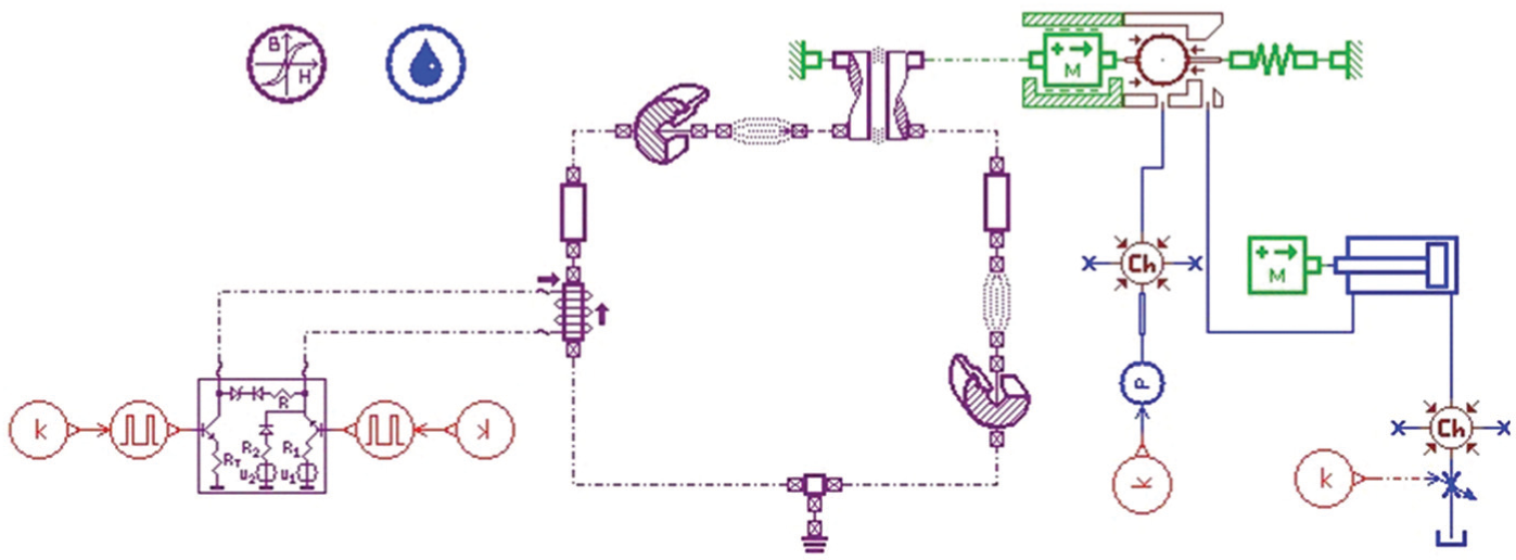
Simulation model of the PCS for HSDV.
Parameter setting of major components in the simulation model.

Results and discussion
PWM signal, coil current, and main spool displacement
As stated above, the displacement and speed of the main spool are controlled by regulating the duty ratio of the PWM signal. In the case of a duty ratio of high-voltage signal τ 1 = 0.1 and a duty ratio of total voltage signal τ 2 = 0.5, the variations in PWM signal, coil current, and main spool displacement with time are obtained as depicted in Figure 5.
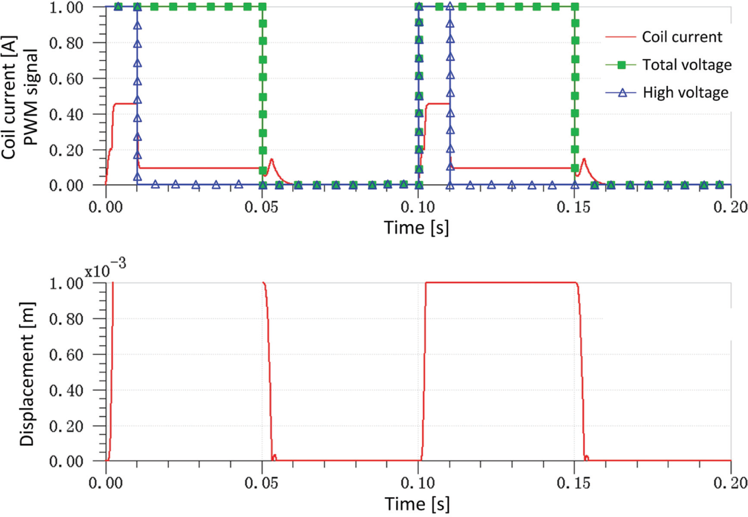
Variations in PWM signal, coil current, and main spool displacement.
As seen in Figure 5, we can draw the following conclusions.
When the starting output voltage of the amplifier circuit is high, it may generate a large current to the coil. Then, the spool becomes to open at a high acceleration due to a great electromagnetic force. Moreover, it can be seen from the figure that the required time for the spool to reach the fully open state, that is, the opening time t on, is 2 ms.
Once the spool is fully opened, only a small electromagnetic force is needed for the HSDV to remain in the open state. Therefore, the high voltage is cut off and the output voltage of the amplifier circuit turns to low-level state.
As the PWM signal begins to drop, the coil current decreases and the electromagnetic force reduces accordingly due to the effect of the diode freewheeling. Once the spring force is greater than the sum of the electromagnetic force and liquid pressure, the spool begins to close gradually. Meanwhile, the required time from the declining moment of the PWM signal to the closing moment of the spool, that is, the closing time t off, is obtained to be 5 ms as seen in Figure 5.
Dynamic property for different duty ratios
Keeping the frequency of PWM signal to be f = 10 Hz and the duty ratio of total voltage current to be τ 2 = 0.5, the variations in PWM signal and spool displacement with various duty ratios of high-voltage signal can be obtained as seen in Figure 6. In Figure 6, the duty ratio of high-voltage signal τ 1 is 0.015, 0.02, 0.025, and 0.05.

Variations in PWM signal and spool displacement for different duty ratios of high-voltage signal: (a) τ 1 = 0.015, (b) τ 1 = 0.02, (c) τ 1 = 0.025, and (d) τ 1 = 0.05.
As seen in Figure 6, the spool cannot open fully when the duty ratio of high-voltage signal τ 1 is 0.015 until τ 1 increases to 0.02. Therefore, we can conclude that the minimum value of τ 1 is about 0.02, that is, τ 1min = 0.02. In practice, a short time of high voltage is better for reducing the hysteresis loss and coil heating in the precondition of satisfying the normally opened spool.
In addition, variation curves of PWM signal and spool displacement for two duty ratios of voltage signal (τ 1 = τ 2 = τ = 0.005 and τ 1 = τ 2 = τ = 0.015) are obtained as shown in Figure 7.
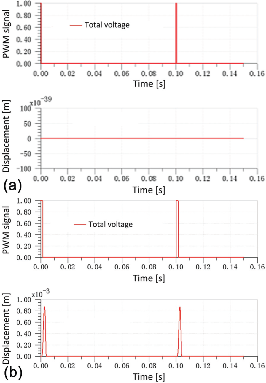
Variation curves of PWM signal and spool displacement for two duty ratios of voltage signal: (a) τ = 0.005 and (b) τ = 0.015.
Keeping the duty ratio of high-voltage signal τ 1 = τ 1min = 0.02 and regulating the duty ratio of total voltage signal τ 2, the variations in PWM signal and spool displacement for various values of τ 2 are gained as presented in Figure 8. In this figure, the value of τ 2 is 0.9, 0.95, 0.98, and 0.995.

Variations in PWM signal and spool displacement for various duty ratios of total voltage signal: (a) τ 2 = 0.9, (b) τ 2 = 0.95, (c) τ 2 = 0.98, and (d) τ 2 = 0.995.
In combination with Figures 7 and 8, the following conclusions can be drawn:
When τ 2 is very small (τ 2 = 0.005), the increasing time of the electromagnetic force is too short. And the maximum electromagnetic force is too small comparing to the required force value for opening the spool. Thus, the spool cannot open at this time.
For a value of τ 2 = 0.015, the maximum electromagnetic force is able to overcome the spring effect and the spool begins to open. However, the electromagnetic force starts to decrease before the spool is fully open which makes the spool close gradually.
While the value of τ 2 increases to 0.98, the electromagnetic force starts to increase before the spool is fully open due to the short declining time of the electromagnetic force. This phenomenon leads the spool to overcome the spring effect and start to open.
Once the value of τ 2 reaches up to 0.995, the spring effect is insufficient to induce the spool to open because the declining time of electromagnetic force is very short and the electromagnetic force is great enough to overcome the spring effect. Therefore, the spool maintains the open state under this circumstance.
Pilot proportional control performance
Figure 9 indicates the variations in PWM signal, spool displacement of HSDV, and main spool displacement with time in the case of τ 1 = 0.02 and τ 2 = 0.5. It can be seen from Figure 9 that the oil flows into the cavity of the main spool to push the spool to move while the spool of the HSDV is open. Also, the main spool displacement presents an approximately linear relationship with time, just as depicted in the main spool displacement curve. Therefore, the proportional control of main spool displacement is achieved by the regulation of the average oil flow while using the HSDV as a pilot valve. Therefore, further research on the main spool displacement is required to verify the proportional control effect of the PCS.

Variations in PWM signal, spool displacement of HSDV, and main spool displacement.
Main spool displacement in several cycles is obtained as plotted in Figure 10. In this figure, the total simulation time is extended to 0.5 s. As can be seen, the main spool displacement in one single cycle presents basically the same. Thus, we can conclude that the main spool displacement is proportional to the cycle number of PWM signal. In practice, proportional control of the main spool displacement can be achieved by adjusting the cycle number of PWM signal. Overall, the PCS of HSDV is capable for the proportional control of the main spool displacement.
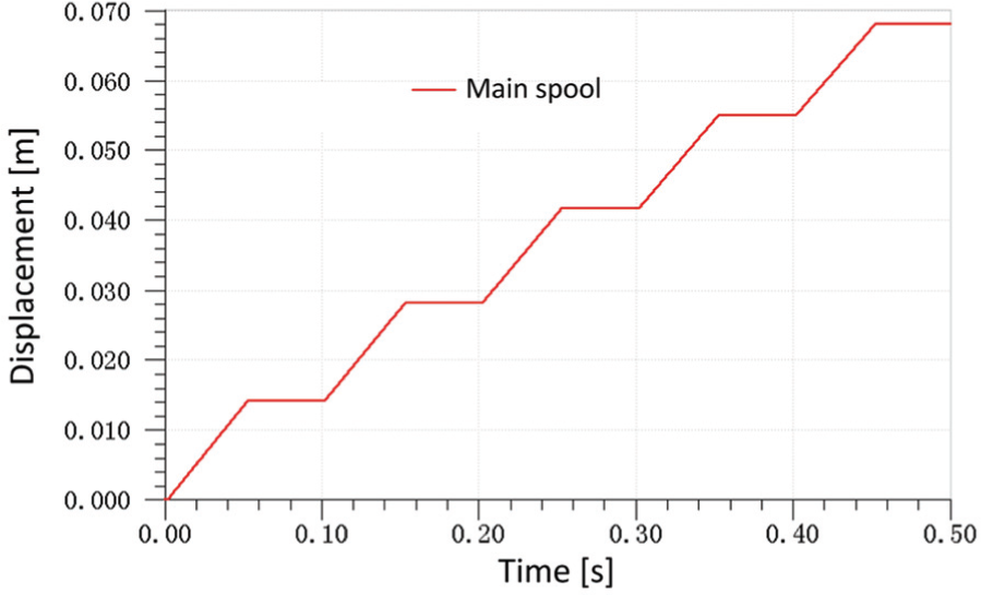
Main spool displacement in several cycles.
Conclusion
This article presents a dynamic simulation and analysis of the dynamic characteristics of the PCS for HSDV as a pilot valve for the directional valve. The simulation was carried out using the AMESim software. Simulation results concerning the PWM signal, coil current, spool displacement of HSDV, and main spool displacement were presented and discussed. They indicate that the opening time of the main spool for the directional valve increases with the duty ratio of the voltage signal. Moreover, the main spool displacement is basically the same in one single cycle of the PWM signal. As a consequence, it is proportional to the cycle number of the PWM signal. On the whole, the designed PCS is proved to possess a good dynamic characteristic for the HSDV as a pilot valve to achieve proportional control of main spool displacement for the directional valve.
Footnotes
Academic Editor: Mario L Ferrari
Declaration of conflicting interests
The authors declare that there is no conflict of interest regarding the publication of this article.
Funding
This work was supported by the State Key Development Program for Basic Research of China (2011CB707305) and the Fundamental Research Funds for the Central Universities (2011HGZ10004).