
Abstract
A rolling bearing plays a key role in the gearbox of the cold rolling mill transmission system. As a result, the degradation and failure of bearings can lead to unplanned shutdowns of the entire rolling mill system. Since on-site cold rolling mills work usually in non-steady lubrication rolling conditions originating form variations of multiple parameters, the uncertainty affecting bearing performance in a cold rolling mill transmission system increases, making it more difficult to assess health status and predict the remaining service life of bearings, Therefore, by establishing a coupling model describing the relationship for the rolling mill and normal /faulty gearboxes under non steady rolling conditions, quantitatively studies the influence of various rolling parameters of a rolling mill on the fatigue service life of bearings in the gearbox of the rolling mill transmission system, and verify the effectiveness of linear cumulative damage theory for bearing fatigue service life through experiments and on-site bearing vibration data. The results indicate that as the thickness of the strip steel inlet, lubricant viscosity, and rolling speed increase, or the thickness of the strip steel outlet and rolling roll radius decrease, the service life of bearings gradually decreases. As the fluctuation amplitude of various rolling parameters in the cold rolling mill increases, the service life of bearings in the gearbox of the rolling mill transmission system gradually shortens. Moreover, when the rolling parameter value or fluctuation amplitude increases to a specific values, the remaining service life of bearings will sharply decrease. Under the same rolling conditions, the service life of bearings in gearboxes with faults decreases more significantly than that in normal gearboxes.
Keywords
Introduction
Cold rolling mill is an important production equipment in steel enterprises. The rolling mill system is mainly composed of the transmission system of the rolling mill (including motor, gearbox, etc.) and the vertical system of the rolling mill (referred to as the rolling mill). As a key component in the gearbox of the cold rolling mill transmission system, bearings are crucial for the safe, reliable, and efficient operation of the process manufacturing industry. For example, during the production process of the second stand of a cold rolling mill in a certain steel plant on May 26, 2022, the bearing in a certain gearbox of the rolling mill transmission system exceeded its safe service life, causing the bearing to lock up, resulting in the fracture of the shaft in the box and the bolt at the connection between the upper and lower boxes. Due to the lack of backup equipment, the rolling mill system was forced to stop production for 120 hours, and the direct and indirect losses amounted to billions of yuan. From this, it can be seen that timely detection, capture, tracking, monitoring, and evaluation of the operating status of bearings, prediction of their remaining life, and adoption of economic and efficient maintenance and updating strategies to achieve early prevention of rolling mill bearing equipment failures and improve the fatigue service life of bearings, ensuring the safe and reliable operation of rolling mills, is an urgent need to support and ensure social and economic development.
At present, the existing methods for early fault detection such as A family of health indicators induced by EOF for condition monitoring of machinery, Coupled neurons with multi-objective optimization benefit incipient fault identification of machinery, 1 Caputo-Fabrizio fractional order derivative stochastic resonance enhanced by ADOF and its application in fault diagnosis of wind turbine drivetrain, 2 Chaotic resonance in a fractional-order oscillator system with application to mechanical fault diagnosis, 3 An adaptive fractional stochastic resonance method based on weighted correctional signal-to-noise ratio and its application in fault feature enhancement of wind turbine. 4 The existing methods for predicting the service life of bearings can be divided into three categories: failure mechanism based, data-driven, and hybrid model-based methods. The data-driven residual life prediction methods represented by artificial intelligence and statistical learning methods5–7 have received widespread attention due to their ability to directly obtain residual life prediction models from data learning.
The traditional service life prediction methods 8 are mainly based on physical formulas to describe the degradation process of bearing performance, such as Paris law and Forman’s law of crack propagation model,9,10 contact stress analysis, 11 and damage mechanics based on stiffness analysis. 12 Empirical models include Wiener process model13,14 and gamma process model. 15 These methods are collectively referred to as model-based methods, as they construct meaningful mathematical function expressions based on the above formulas or models. Essentially, the “model” applied in model-based methods represents prior knowledge summarized by experts about the regularity of performance degradation processes. The parameters in the model can be estimated using only a small amount of data collected from sensors; Then the service life can be calculated. However, the knowledge contained in the model does not always match the facts, which means that there may be biases due to incomplete factors or a lack of stochastic process descriptions.
In recent years, with the continuous development and innovation of intelligent optimization algorithms, deep learning has been widely applied in data-driven bearing life prediction research, such as a novel health indicator based on the Lyapunov exponent, a probabilistic self-organizing map, and the Gini-Simpson index for calculating the RUL of bearings, 16 convolutional neural networks (CNN),17,18 long short term memory networks19,20 and autoencoders.21,22 These deep learning algorithms are applied in equipment life prediction tasks, the main approach is to train a neural network model by constructing a health index and setting target labels, and then use the trained model to predict the service life of the equipment.
In order to construct an intelligent degradation model for rolling bearings, Wang and Xiang. 23 proposed an improved EM to predict the RUL of rolling bearings, Firstly, an adaptive method based on kurtosis and root mean square (RMS) of bearing vibration signals is used to determine the appropriate FPT. Secondly, gradient descent method is used to reliably optimize the EM. Kumar et al. 24 proposed an intelligent framework that seamlessly integrates degradation monitoring, defect identification, and remaining useful life (RUL) estimation, providing a comprehensive and holistic solution for bearing health assessment. Zhou et al. 25 proposed a bearing service life prediction method based on a combination of short-time Fourier transform and CNN. This method uses the time-frequency map of the original vibration signal constructed by the short-time Fourier transform as the model input for life prediction. Ding et al. 26 proposed a bearing service life prediction method based on CNN. Firstly, use 3σ the criterion is to denoise the original data, and then combine it with fast Fourier transform to obtain the frequency characteristics of the original data. Finally, these obtained features are used as model inputs for predicting the service life of bearings. Cheng et al. 27 proposed a multi bearing life prediction method that combines empirical mode decomposition with bidirectional long short-term memory networks.
In summary, domestic and foreign scholars have achieved breakthrough conclusions in predicting the fatigue life of bearings. However, there are few reports on the life prediction of bearings in the gearbox of rolling mill transmission systems. The reason for this is that this study requires a large amount of experimental or engineering data support. In actual engineering of rolling mill systems, subjective factors such as unclear influencing factors and mechanisms, as well as objective factors such as complex on-site conditions and high equipment stiffness, have an impact, It makes it difficult to obtain the stress values and related engineering data of bearings, and ultimately, due to incomplete influencing factors and lack of data, the accuracy of predicting the bearing service life in the rolling mill transmission system is very low. Therefore, based on the achievements of domestic and foreign scholars in predicting bearing life, this article will establish rolling models of rolling mills under different rolling conditions, obtain vibration acceleration spectra of bearings in the gearbox of the rolling mill transmission system under different rolling conditions, clarify the vibration mechanism of the rolling mill system, and solve problems such as unclear factors affecting bearing vibration, And based on simulation data and engineering data, the bearing vibration acceleration spectrum is converted into a nominal stress load spectrum. As real-time monitoring of the bearing vibration acceleration value in the rolling mill site is relatively easy to achieve, it overcomes the problems of complex on-site conditions and difficulty in measuring engineering stress data, achieves indirect real-time measurement of bearing stress value and related engineering data, and increases the engineering data for predicting the bearing life in the gearbox of the rolling mill transmission system, Improve the accuracy of service life prediction.
Dynamic rolling torque model of rolling mill under non steady lubrication Rolling conditions
The lubrication state of the rolling mill during the process of rolling strip steel includes three parts: fluid lubrication, mixed lubrication, and boundary lubrication. The lubrication state is determined by the ratio of the minimum oil film thickness between the roll gaps to the surface roughness of the rolling rolls and the rolled parts.
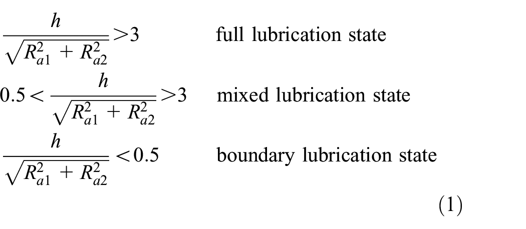
In the formula,
In the actual rolling process of strip steel, the dynamic roller gaps are generally in a mixed lubrication state, so the friction between the roller gaps is generally mixed friction, that is, part of the roller and the rolled piece are in contact with lubricating oil, and the other part is in rough contact with the surface of the rolled piece through the roller. When the rolling mill is in a mixed lubrication state, the frictional shear stress can be expressed as:

In the formula,

In the formula,
Assuming that the thickness of the oil film in the work area satisfies continuity, that is, the grooves on the rough surface of the work area are filled with lubricating oil. Therefore, the calculation method of the oil film thickness in the mixed lubrication state can be obtained through the theory of full oil film lubrication, and

Using equations (2) and (4), and based on the solution method for rolling force and friction force under full oil film lubrication, 28 the expressions for rolling force and tangential friction force in the working area under mixed lubrication state are obtained as follows:


The tangential friction force acting on the roller in a mixed lubrication state consists of two parts. The first part is the tangential friction force generated by the viscosity of the lubricating oil, and the second part is the tangential friction force generated by the rough contact between the roller and the surface of the rolled piece. At any given moment, the area ratio occupied by the first part in the working area is:

The tangential friction force generated in the working area in the second part can be obtained by multiplying the rolling force by the friction coefficient, and the expression of the friction coefficient f is:

In the formula,
By combining equations (7) and (8), the total frictional force acting on the tangent direction of the roller can be obtained, and then the torque acting on the roller can be obtained. The expression is:


In the formula,
Substituting equations (5) and (6) into equation (10) yields the expression for the non-dimensional dynamic rolling torque acting on the rolling mill:

The expression for the thickness of rolled parts in the workspace can be expressed as:

Substituting equation (12) into (11) and solving equation (9) can obtain the functional relationship between different rolling parameters such as strip inlet/outlet thickness, post tension, rolling speed, roll radius, reduction rate, and lubricant viscosity and the load torque value acting on the output end of the gearbox in the rolling mill transmission system at different times.
Establishment of coupling model between rolling mill and gearbox of the rolling mill transmission system
Establishment of nonlinear models for normal and root cracked gearboxes
Based on the gearbox model in reference,
28
a 13 degree of freedom nonlinear dynamic model of the gearbox is established considering time-varying mesh stiffness (


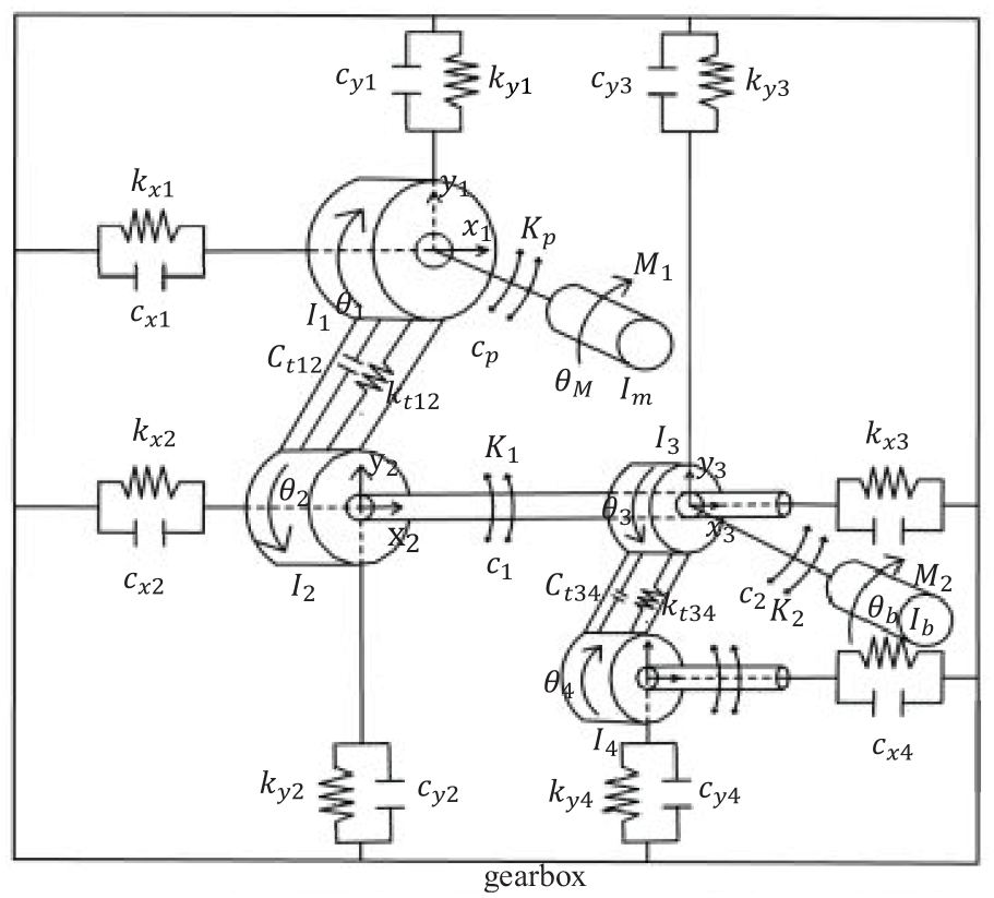
Dynamic model of 13 degree of freedom gearbox system.
Among them, the gear mass matrix M, the axial support stiffness matrix


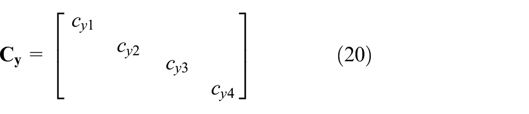


In the formula,
The moment of inertia of each component can be calculated by material mechanics, and its calculation formula is:

In the formula,
Establishment of coupling model between rolling mill and gearbox under non steady lubrication state
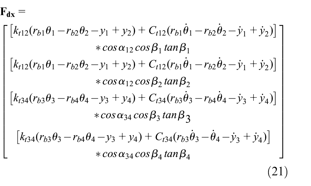
The time-varying rolling torque generated by the rolling mill during the process of rolling strip steel is transmitted to the gearbox through the universal coupling, and the torque generated at the output end of the gearbox serves as power to provide a driving torque to the rolling mill (as shown in the model in Figure 2). However, due to the inclination angle of the universal coupling, it is impossible for all the torque generated at the output end of the gearbox to act on the rolling mill, The dynamic rolling torque generated during the rolling process cannot all act on the output end of the gearbox. Therefore, based on the dynamic rolling torque


Dynamic model of coupling between rolling mill and gearbox.
In the formula,
By jointly solving equations (9), (13)–(27), and (29)–(32), and through simulation calculations, the relationship between the variation characteristics of various rolling parameters and the vibration characteristics of the gearbox under non steady lubrication conditions can be obtained.
Method for predicting the fatigue life of bearings in the gearbox of rolling mill transmission system
The process flow of bearing life prediction method used in this study is shown in Figure 3.
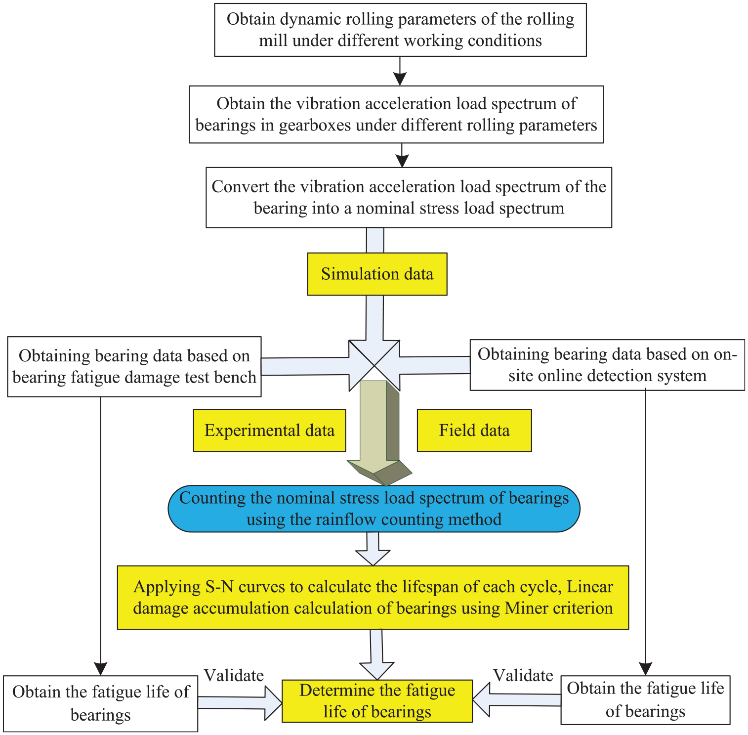
Flow chart of bearing life prediction.
Stress life curve of bearing materials
The bearings in the gearbox of the rolling mill transmission system belong to high cycle fatigue. Therefore, this article is based on the fatigue life prediction method proposed by Wöhler. Standard fatigue specimen tests are conducted on rotating bending and high-frequency tensile compression fatigue testing machines to obtain the stress-strain curve. A set of specimens with the same bearing material and size as those used in this article are used for the test. The stress ratio R = −1 is taken for cyclic loading, and fatigue tests are conducted at different stress levels until the specimens fail. Draw the test results into an S-N curve as shown in Figure 4, with the maximum stress

S-N curve of bearing material.
Using linear accumulation method to determine the fatigue life of bearings
The fatigue process of bearings in the gearbox of the rolling mill transmission system can be seen as both the accumulation process of damage approaching a critical damage value and the consumption process of material inherent life. Therefore, this article applies the linear cumulative damage theory to predict the service life of bearings, and the principle is as follows.
The damage increases linearly with the number of cycles at various stress levels, as shown in Figure 5(a) and (b). If the material undergoes N1 cycles of failure at the
When the fatigue damage reaches its limit (D = 1), failure occurs, that is, D = N1/N1.

Schematic diagram of damage accumulation calculation. (a) The number of times the material acts at each load level and (b) the number of cycles of materials at various load levels.
If the material undergoes N2 cycles of failure at

Similarly, D3 = n3/N3.
Under the action of stress less than the fatigue limit of
When the damage caused by various levels of load reaches the limit, the D value is equal to 1, and the material fails, Using the linear accumulation formula, then:

Namely

A study on the influence of different rolling conditions on the service life of bearings under non steady state lubrication conditions
Based on the nonlinear coupling model between the rolling mill and gearbox established in this article, the relationship between the changes in rolling parameters of the rolling mill and the vibration characteristics of the gearbox under non steady lubrication state can be obtained through simulation. On this basis, the influence of different rolling parameters on the service life of bearings in the gearbox of normal and faulty rolling mill transmission systems is studied. The bearing model used in the gearbox of the rolling mill transmission system is SDAF23272 self-aligning roller bearing. The equivalent dynamic load calculation formula can be expressed as:

In the formula,
The influence of various rolling parameter values in rolling mill systems on the service life of bearings
Using the coupling model between rolling mill and gearbox established in this article, the vibration acceleration spectrum (including axial and radial directions) at the gearbox bearing seat corresponding to a certain dimensionless rolling speed, strip inlet/outlet thickness, rolling roll radius, and lubricant viscosity value within 1 h can be obtained through simulation. The nominal stress load spectrum of the bearing under this rolling parameter value can be obtained through conversion calculation. By using the bearing life prediction method established in this article for the gearbox of the rolling mill transmission system, the fatigue service life of the bearing under this nominal stress load spectrum can be obtained, and finally the fatigue service life of the bearing under this equivalent acceleration load spectrum can be obtained. Similarly, the fatigue life of bearings can be obtained under other non-dimensional rolling speeds, strip inlet/outlet thickness, roll radius, and lubricant viscosity values, as shown in Figure 6(a)–(e).

The influence of various rolling parameter values on the service life of bearings. (a) Dimensionless strip inlet thickness, (b) dimensionless strip steel outlet thickness, (c) roll radius value, (d) lubricating fluid viscosity value, and (e) dimensionless rolling speed.
From Figure 6(a)–(b), it can be seen that the service life of bearings decreases with the increase of the non-dimensional strip inlet thickness or the decrease of the strip outlet thickness. When the non-dimensional strip inlet thickness is greater than 1 or the non-dimensional strip outlet thickness is less than 1, the service life of bearings will sharply decrease with the increase of the strip inlet thickness or the decrease of the strip outlet thickness, The reason is that as the thickness of the strip steel inlet increases or the thickness of the strip steel outlet decreases, the fluctuation amplitude of the rolling torque gradually increases, causing the load fluctuation amplitude acting on the output end of the gearbox to increase, thereby increasing the vibration acceleration amplitude of the gearbox, and ultimately leading to an increase in the stress load spectrum used on the bearing. When the load exceeds the rated dynamic load of the bearing, the service life of the bearing will sharply decrease.
From Figure 6(c), it can be seen that the service life of the bearing decreases with the decrease of the roll radius, and under the same roll radius, the service life of the bearing in the gearbox with root crack faults is shorter than that of the bearing in normal gears. When the roll radius value is less than 0.336 m, the service life of bearings in the normal gearbox begins to rapidly decrease, while the service life of bearings in the gearbox with root crack faults begins to rapidly decrease when the roll radius value is less than 0.338 m.
From Figure 6(d), it can be seen that the service life of the bearing decreases with the increase of lubricant viscosity, and the service life of bearings in gearboxes with crack faults is shorter than that of bearings in normal gearboxes. From Figure 6(e), it can be seen that as the dimensionless rolling speed increases, the service life of bearings gradually decreases. At the same rolling speed, the service life of bearings in gearboxes with root crack faults is shorter than that in normal gearboxes. When the dimensionless rolling speed is lower than 1.1, the service life of the bearing is not significantly affected by the rolling speed. When the dimensionless rolling speed is higher than 1.1, the service life of the bearing significantly decreases with the increase of rolling speed. This is because when the dimensionless rolling speed is higher than 1.1, the vibration acceleration amplitude of the gearbox increases sharply, causing the equivalent dynamic load on the bearing to increase sharply, exceeding the rated dynamic load of the bearing and leading to a sharp decrease in the service life of the bearing.
Therefore, selecting appropriate rolling parameter values can not only prolong the service life of bearings, but also reduce the vibration amplitude of the gearbox and the entire rolling mill system, reduce the occurrence rate of faults, improve the service life of equipment, and increase the quality of strip steel products.
The influence of the fluctuation amplitude of various rolling parameters in the rolling mill system on the service life of bearings
Similarly, based on the nonlinear coupling model between the rolling mill and gearbox established in this article, and using the bearing life prediction method in the gearbox of the rolling mill transmission system established in this article, the influence of different dimensionless strip steel inlet/outlet thickness, rolling roll radius, and lubricant viscosity fluctuation amplitude on the service life of bearings in the gearbox of the rolling mill transmission system with normal and root crack faults under non steady lubrication state can be obtained through simulation. The results are shown in Figure 7(a)–(d).

The influence of the fluctuation amplitude of various rolling parameters on the service life of bearings. (a) Dimensionless strip inlet thickness, (b) dimensionless strip steel outlet thickness, (c) roll radius value, and (d) lubricating fluid viscosity value.
From Figure 7(a) and (b), it can be seen that the service life of the bearing decreases with the increase of the fluctuation amplitude of the non-dimensional strip steel inlet/outlet thickness. When the fluctuation amplitude exceeds 0.06, the service life of the bearing will sharply decrease. And the bearing service life is shorter in gearboxes with root crack faults. From Figure 7(c) and (d), it can be seen that the service life of the bearing gradually decreases with the increase of the fluctuation amplitude of the rolling radius or the viscosity of the lubricant. When the fluctuation amplitude reaches a specific values, the service life of the bearing will sharply decrease.
Therefore, moderate control and reduction of the fluctuation amplitude of the thickness at the inlet and outlet of the strip steel, the fluctuation amplitude of the rolling mill radius, and the fluctuation amplitude of the lubricant viscosity can prolong the service life of bearings, reduce the vibration amplitude of the gearbox and the entire rolling mill system, reduce the occurrence rate of faults, improve the service life of the equipment, and increase the quality of the strip steel products.
Verification of the effectiveness of bearing life prediction methods
Experimental verification of bearing fatigue damage in the gearbox of rolling mill transmission system
Bearing fatigue damage test
To verify the accuracy of the bearing fatigue life prediction method, fatigue failure tests were conducted on the 6313-2RS self-lubricating ball bearing, as shown in Figure 8. The 6313-2RS self-lubricating ball bearing has 8 rolling elements, a rolling element diameter of 24 mm, a maximum speed of 5800 rpm, a rated dynamic load of 93.8 kN, an equivalent dynamic load of 29.8 kN, a test speed of 1300 rpm, an external dimension of 65 mm × 140 mm × 33 mm, and a mass of 2.08 kg. In the experiment, sensors 1 and 2 were arranged in the axial direction of the bearing housing, while sensors 3 and 4 were arranged in the vertical direction. The sampling frequency was set to 5 kHz, the sampling length was 4096, and the sampling interval was 60 s. Four channels of vibration acceleration signals were collected.

Data collection site layout.
The experiment started on June 28th and continued until noon on July 14th when the test was shut down. After dismantling and cleaning the bearing fatigue testing machine, on-site testers found that the inner ring of the test bearing had circumferential fatigue peeling with a large arc angle due to the drying of the sealed self-lubricating grease, as shown in Figure 9.

Test bearing and its inner ring exfoliation diagram.
Failure identification based on the root mean square (RMS) value, skewness, and peak to peak value of the first channel, in frequency domain analysis, the relevant frequencies of the bearing, such as rotation frequency Fr, cage fault frequency FTF, rolling element rotation frequency BSF, outer ring fault frequency BPFO, and inner ring fault frequency BPFI, are first calculated, as shown in Table 1. Finally, the calculated frequency value is corrected. Frequency correction refers to the correction of the calculated value based on the frequency resolution set by the signal acquisition parameters.
Relevant frequencies of 6313-2RS self-lubricating ball bearings.

Figures 10 and 11 show the trend of RMS value, skewness, and peak to peak value changes in the vibration of the test bearing. From Figure 10, it can be seen that there are many outliers in the RMS value, skewness, and peak to peak value characteristics, which are caused by the interference introduced by on-site testing personnel who need to judge whether the test bearing has failed. By judging the RMS value, skewness, and peak to peak value of bearing vibration, it can be concluded that: (1) from the beginning of signal acquisition to the 6250th sampling point is the degradation zone of the test bearing performance; (2) The failure of the test bearing occurred around the sampling point 6250, on July 14th at 07:08.

The change trend value of first channels. (a) Root mean square value and (b) peak to peak value.

Enlarged local graph of the change trend value of first channels. (a) Root mean square value, (b) peak to peak value, and (c) skewness.
Calculating the fatigue life of bearings using the stress life method
Take the axial and radial vibration acceleration spectra at the bearing seat from the online monitoring data within 1 min, and apply equation (37) to calculate the equivalent vibration acceleration spectrum at the bearing seat within 1 min, as shown in Figure 12. Through conversion calculation, convert the equivalent vibration acceleration spectrum in Figure 12 into the nominal stress load spectrum of the bearing, as shown in Figure 13. Using the calculation method in section “Using linear accumulation method to determine the fatigue life of bearings,” use the load spectrum as an impact load spectrum to calculate its damage value. The solution result is the damage value D = 0.00031 per min. This means that the bearing was damaged after a total of 32782.15134 cycles in the load spectrum, and the time for each load spectrum is 1 min. So, the damage to the bearing will take a total of 32782.15134/60/24 = 22.765 days. The service life of bearings measured in the experiment is 15 days, with an error within two factors, which further proves the effectiveness and feasibility of the fatigue life prediction method for predicting the fatigue service life of bearings.

Equivalent vibration acceleration spectrum of bearings.

Bearing nominal stress load spectrum.
Engineering verification of bearing fatigue damage in the gearbox of rolling mill transmission system
Due to the harsh working conditions and various limitations of the steel plant, it is difficult to monitor the stress of bearings in the gearbox in real time. However, it is relatively easy to achieve real-time monitoring of the vibration acceleration value of bearings on site. In addition, a wireless vibration monitoring system has been installed in the gearbox of the steel plant, which can easily obtain the vibration acceleration spectrum of bearings.
Therefore, this section converts the equivalent vibration acceleration spectrum of bearings collected on site into the nominal stress load spectrum through equivalent conversion. The method is to simultaneously detect the vibration acceleration value (including radial and axial) and stress value at the bearing seat of the gearbox (as shown in the on-site test diagram in Figure 14), to obtain the vibration acceleration value and stress value at the bearing seat at the same time and under the same working condition. Multiple sets of data are measured and their average values are calculated, and the conversion relationship between the vibration acceleration value and stress value at the bearing seat can be obtained. Finally, the equivalent vibration acceleration spectrum at the bearing seat of the gearbox under on-site working conditions (as shown in Figure 15) can be converted into a nominal stress load spectrum (as shown in Figure 16).
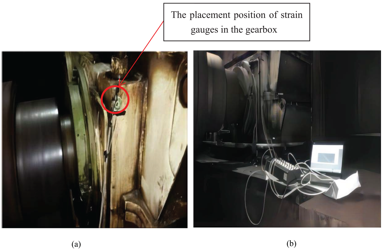
The field collection diagram of the stress value of the gearbox. (a) The placement position of strain gauges in the gearbox and (b) stress-strain acquisition instrument.

Equivalent vibration acceleration spectrum at the bearing seat of the gearbox.

Nominal stress spectrum at the bearing seat of the gearbox.
The above method can be used to obtain the stress load spectra of the rolling mill under various rolling conditions. Using the calculation method in section “Using linear accumulation method to determine the fatigue life of bearings,” the stress load spectra under different rolling conditions are used as an impact load spectrum to calculate their damage values. The solution result is: the damage D per hour is 0.0000290–0.0000953, which means that the bearing is damaged after a total of 34490–78125 cycles in this load spectrum, and the time for each load spectrum is 1 h. So, the damage to the bearing takes a total of 34490–78125 h.
The bearing at the input end of the gearbox in the transmission system of the second cold continuous rolling mill system of the steel plant (the coupling model between the rolling mill and gearbox in this article is based on this rolling mill system) was installed and used in January 2013. The outer ring of the bearing showed indentation (as shown in Figure 17) in February 2022. During this period, it underwent shutdown maintenance and regular maintenance, and the total working time was about 8 years and 10 months, with a total operation time of over 67,000 h. The bearing life prediction method used in this article predicts a service life range of 34,490–78,125 h under various rolling conditions.

Bearing map of outer ring indentation in gearbox.
The fatigue damage engineering test of the bearing verifies the effectiveness and practicality of the bearing service life prediction method, which provides an important theoretical basis for predicting the life of other components in the subsequent rolling mill system.
Conclusion
(a) The service life of bearings decreases with the increase of rolling speed, lubricant viscosity, and strip inlet thickness, or the decrease of strip outlet thickness and roll radius. When reach a specific value, the service life of bearings will sharply decrease with the increase of rolling speed, lubricant viscosity, and strip inlet thickness, or the decrease of strip outlet thickness and roll radius.
(b) The service life of bearings decreases with the increase of non-dimensional strip inlet thickness, outlet thickness, rolling radius, and lubricant viscosity fluctuation amplitude. When the fluctuation amplitude exceeds a specific values, the service life of bearings will sharply decrease. Therefore, moderate control of the rolling parameter values and their amplitude fluctuations can not only prolong the service life of bearings, but also reduce the vibration amplitude of the gearbox and the entire rolling mill system, reduce the occurrence rate of faults, improve the service life of rolling mills, and increase product quality.
(c) Under the same rolling conditions, the service life of bearings in gearboxes with faults is shorter than that of bearings in normal gears. when the service life of bearings begins to sharply decrease, the rolling parameter values in normal gearboxes are higher than that in gearboxes with faults.
(d) By conducting fatigue damage tests on the 6313-2RS self-lubricating bearing, the error between the test results and the simulation results is within two factors, which verifies the correctness of the linear cumulative damage theory for predicting the service life of the bearing. Through on-site damage testing of bearings, verifies the effectiveness and practicality of the linear cumulative damage theory for predicting the service life of the bearing. Therefore, the bearing fatigue life prediction method established in this paper can provide a theoretical basis for predicting the fatigue service life of bearings in the gearbox of rolling mill transmission systems.
Footnotes
Handling Editor: Qibin Wang
Declaration of conflicting interests
The author(s) declared no potential conflicts of interest with respect to the research, authorship, and/or publication of this article.
Funding
The author(s) disclosed receipt of the following financial support for the research, authorship, and/or publication of this article: This work was supported by the Weifang University Research Initiation Fund (Grant Nos 209/44122028).
Data availability
Data will be made available on request.