
Abstract
With the increasing span of steel box-section arch bridges, the stability and ultimate strength of arch ribs under horizontal loading become crucial for earthquake resistance. This paper presents a numerical study on the cyclic behavior of steel box-section twin arch ribs under out-of-plane horizontal cyclic loading to assess the seismic performance of steel box-section twin arch ribs. Seventy-two finite element (FE) models of arch ribs were established and validated based on previous experimental studies. An pseudo static elasto-plastic numerical analysis was conducted to investigate the influence of the inclination angle, rise-span ratio, and width-span ratio on the cyclic behavior of the arch ribs. The results indicate that as the angle of inclination and width-span ratio increase, or as the rise-span ratio decreases, the initial stiffness and ultimate strength of the arch ribs improve. However, this also leads to an increase in internal forces within the transverse brace, resulting in local instability and damage. In addition, the inclination angle of the arch rib and the span-to-rise ratio may influence the yielding sequence of the components. Therefore, while increasing the angle of inclination of the arch rib can enhance the transverse cyclic behavior of the steel box-section twin arch ribs, it is important to consider the potential adverse effects caused by the increased internal forces on the transverse brace.
Keywords
Introduction
In recent years, steel arch structures have been widely applied in long-span bridges.1,2 As the span of the arch bridge increases, the stability and ultimate strength under horizontal loading (earthquake, wind, etc.) become important.3,4 Many experimental and theoretical studies have been reported in reference to the elastic and elastoplastic stability of arches. Sakimoto et al.,5,6 Sakata et al., 7 and Yabuki et al. 8 studied the effects of different cross-section forms of twin arch ribs and support forms between arch ribs on the out-of-plane elastoplastic stable strength of the arch structure by means of uniform load tests on arch ribs, and proposed a formula for calculation of the stable strength of the arch structure by using the method of equivalent slenderness ratio. Pi et al.9–11 studied the influences of the rise-span ratio, form of arch rib cross-section, type of vertical load, etc. on the in-plane strength of an arch structure through theoretical and numerical analysis, and proposed design formulas for the in-plane strength of the arch structure by using the principle of pressure-bending correlation curve and considering the loading mode. Thereafter, scholars used experimental and finite element (FE) analysis methods to study the influences of arch rib bending and torsion coupling, support conditions, spandrel structure, and angle of inclination of the arch rib on the stable strength of the arch rib, which showed that the adverse influences of arch rib bending and torsion coupling on out-of-plane stable strength should not be neglected in the design of such arch bridges, and the arch foot fixation, considering the influences of arch building and inclination of the arch rib can improve the in-plane and out-of-plane stable capacity of the arch bridge.12–19 These research results provided the scientific and theoretical basis for the design and construction of steel arch bridges.20–22
However, steel arch bridges have been damaged in many earthquakes.23–25 This makes the seismic performance of steel arch bridge gradually attract more attention, and scholars are also increasingly studying this aspect of their behavior.26–30 Sun et al. 31 investigated the impact of the inclination angle of the arch rib (0°, 4°, and 7°) on the longitudinal and transverse seismic performances of arch bridges. Xia and Zhong 32 assessed the seismic performance of Nanjing Dashengguan Yangtze River Bridge when subjected to non-uniform seismic excitations. Álvarez et al. 33 carried out the seismic assessment for a long-span arch bridge considering the variation in axial forces. Usami et al. 34 and Lu et al. 35 used elastoplastic time history analysis and pushover analysis to explore the evaluation method of seismic performance of steel arch bridges under rare earthquake excitation. Tang et al. 36 and Wang et al. 37 explored the effects of beam-shell multi-scale modeling and hysteretic constitutive models of steel on the seismic performance of steel arch bridges, respectively, to improve the accuracy of elastoplastic dynamic time analysis of steel arch bridges. Sano et al., 38 Usami et al. 39 investigated the strength of parallel twin arch ribs under horizontal cyclic loading by experiments and FE analysis, as well as obtained a study on the seismic performance of arch ribs for transverse direction and an application of the strength-related performance verification method to steel twin arch-rib structures under cyclic loading. Sui et al. 40 conducted a numerical analysis of a steel arch bridge with dampers and the seismic response of the steel arch bridge was improved by installing dampers. Wang et al. 41 used a deck steel basket-handle arch bridge as the research background, and established four FE models of arch bridges with arch rib angle of inclinations of 0°, 4°, 8°, and 12°, conducted non-linear dynamic time history analysis under rare earthquake excitation; the results show that increasing the angle of inclination of the steel twin arch ribs can reduce the response displacement of the steel arch bridge. Although some researches have been done on the stability and dynamic response of steel arch bridges, the cyclic properties of steel arch ribs under out-of-plane horizontal cyclic loads (such as generated by ground motions) are still unclear, and there are few studies on the force condition of a single component.
Against this backdrop, a detailed study was initiated on the cyclic performance of steel arch bridges with box-section twin ribs. A three-dimensional spatial multi-scale FE model was developed for the arch structure under laterally horizontal cyclic loading. The parametric analysis conducted aimed to evaluate the impact of various parameters such as the arch rib angle of inclination, the rise-span ratio, and the width-span ratio on its cyclic properties. Efforts were made to ascertain the yielding sequence patterns of the arch bridge components, the ultimate strength of the structure, and the internal forces of transverse braces under different settings. The results can provide a theoretical basis for improving the seismic performance of steel arch bridges and the seismic design of bridges. The flow chart of the research is shown in Figure 1.

Flow chart.
Steel twin arch rib structure with box-section
The present study focuses on typical steel twin arch ribs with the lateral bracing system to assess the out-of-plane cyclic behavior, which consists of two steel arch ribs with box-section and 10 X-shaped bracings, as shown in Figure 2. In the figure, f means the rise of the arch ribs, L represents the span of the arch ribs, α refers to the angle of inclination of the arch ribs. B stands for the distance between arch feet, b presents the distance between arches vault, and the bracings are named No. 1 to No. 5. The sections of arch ribs, diagonal bracings, and transverse bracings are welded box section, steel pipe, and steel channel section, respectively, and the arch axis is deemed to be a quadratic parabola.
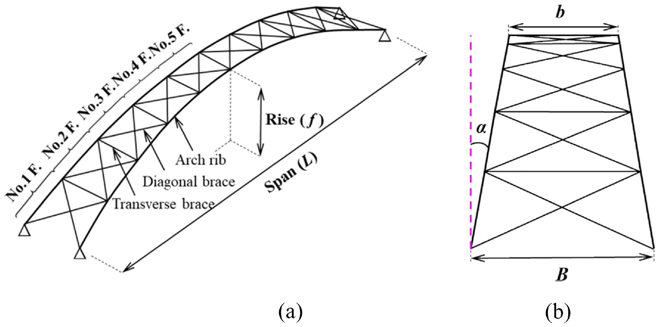
Steel twin arch ribs with the lateral bracing system: (a) configuration of steel twin arch ribs and (b) layout of bracing.
Numerical simulation
FE model
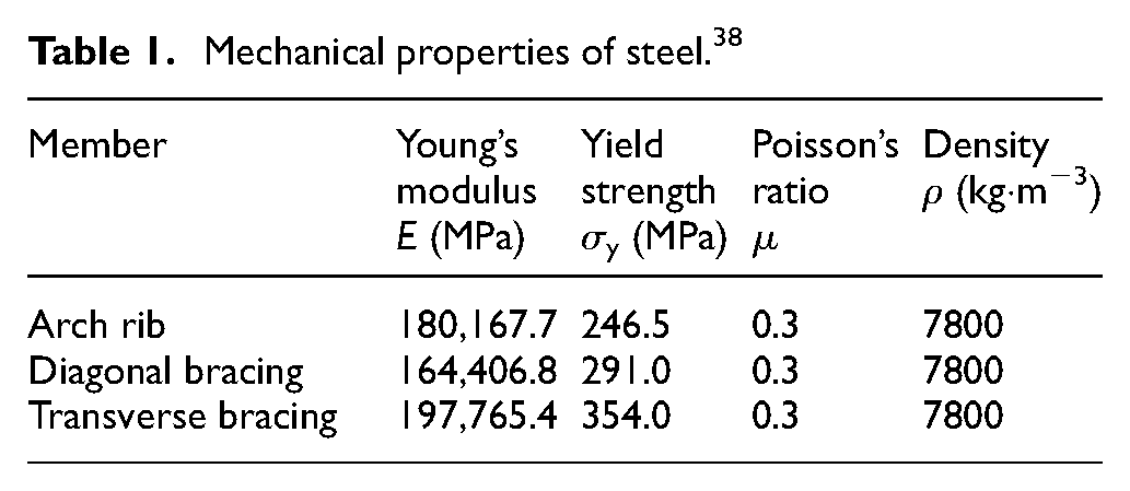
The software ABAQUS was used to build the FE model of steel box-section twin arch ribs. The steel twin arch ribs, diagonal bracings, and transverse bracings were simulated with B31 beam element (Timoshenko beam). The arch feet and mid-span transverse bracing prone to buckling, such as, were simulated by the S4R shell element (Figure 3). The stress-strain relationship is described by a bilinear model, where the plastic secant modulus is 1% of Young’s modulus. Mechanical properties of the steel, derived from experimental tests, are summarized in Table 1. 38 In addition, the kinematic hardening model considering the Bauschinger effect was employed to reflect the cyclic behavior of steel under horizontal cyclic loading.

FE model of steel twin arch ribs with the lateral bracing system.
Mechanical properties of steel. 38
For boundary conditions, the freedoms of arch feet along the X, Y, and Z-directions were constrained, and all rotational freedoms of the arch feet were released.
For the loading condition of FE models, the vertical load was applied first to simulate the effect of dead loads, and then lateral load was applied. Among them, the vertical load represents the self-weight of the arch rib and the external load on the arch rib, which was applied on the joints between arch ribs and bracings, represented by F v , and its value was calculated based on the axial force at the arch feet of the steel box-section twin arch ribs. 38
A cyclic displacement load applied on the arch vault (Figure 4), in which the yield displacement δ y of the steel twin arch ribs is determined by pushover analysis.

Load arrangement and loading protocol: (a) load arrangement schematics and (b) loading protocol.
Validity verification
Based on results of a quasi-static test of steel twin arch ribs, 38 the effectiveness of the FE model was validated. In the test, the span of the arch ribs L is 13,000 mm, the distance between the arch ribs B is 1000 mm, and the rise of the arch ribs f is 2200 mm, as shown in Figure 5(a). For the configuration of twin arch ribs and bracings, the section of arch ribs is a 170 mm × 120 mm box section, and the arch axis is deemed to be a quadratic parabola. The diagonal bracing is a steel pipe with an outer diameter of 48.6 mm and a thickness of 2.3 mm, and the transverse bracing is a steel channel section with a length of 150 mm, outer branch of 50 mm, and thickness of 3.2 mm, as shown in Figure 5(b)–(d).

Test specimen and sectional size of arch component (unit: mm): (a) test model schematic diagram, (b) arch rib, (c) diagonal bracing, and (d) transverse bracing.
The test specimen was positioned within the loading frame, with the arch feet and support platform connected via a hinge pin configuration. Concrete blocks were utilized to simulate the self-weight of the arch as well as the vertical gravity exerted by the structure. Each node experienced half of the gravitational force from a single concrete block (15 kN). To apply a transverse hysteresis force on the arch vault, a horizontal jack was employed through the loading beam. Horizontal cyclic loading was performed on the arch vault, with the amplitudes of the tensile half cycles set at 1.0, −1.0, 1.7, −1.7, 2.0, −2.0, 2.5, and −2.5 times the yield displacement (δy = 75 mm) as shown in Table 2. The test schematic diagrams are presented in Figure 6.
Loading protocol.


Test schematic diagrams 38 : (a) panorama of test specimen and (b) loading schematic diagram.
The hysteretic curves derived from both the experimental tests and numerical simulations at the arch vault exhibit similar results, as shown in Figure 7. Furthermore, the numerical simulation produced the same failure mode as the test, reproducing the local buckling deformation observed on the arch rib in the test (Figure 8). Table 3 lists the critical properties obtained from both tests and numerical simulations, including initial stiffness, yield load, and ultimate load. The maximum errors of initial stiffness and load obtained by numerical simulations are controlled to be within 3.65% and 5.43%, respectively. Therefore, it can be concluded that the FE model has acceptable accuracy.

Comparison of simulated horizontal load-displacement hysteretic curves at corresponding arch vault and test results: (a) case 1 and (b) case 2.

Buckling deformation and stress contours of the arch rib (experimental cases 1 and 2): (a) local deformation of the arch rib case 1, (b) local deformation of the arch rib case 2, (c) buckling deformation and stress contours of the arch rib case 1, and (d) buckling deformation and stress contours of the arch rib case 2.
Comparison of simulation and test results.

Parametric analysis and discussion
Parameter selection
In this study, the rise-span ratio f/L, width-span ratio b/L, and angle of inclination of twin arch ribs α are selected as research parameters to analyze their effects on the cyclic behavior of steel box-section twin arch ribs under laterally horizontal cyclic loading. The range of parameters can be determined by considering structural design, number of models, and mechanical characteristics of arch structure (Table 4). A total of 72 FE models were established. The cross-sectional dimensions of the FE model are as per Figure 2 and b is 1000 mm.
Dimensions and design parameter of model.

The yield displacement of the component
δ y,ar , δ y,db , and δ y,tb , respectively, represent the horizontal displacement of the arch vault corresponding to the yielding of arch ribs, diagonal braces, and transverse braces (Table 5). The values marked in the bold in the table represent the displacement of the first yielding component of the arch. By comparing the relationship between δ y,ar , δ y,db , and δ y,tb , the rule governing the order of yielding for each component of the arch under horizontal transverse load is obtained as follows:
(1) When the angle of inclination is 0°, the yield order is arch rib, diagonal brace, and transverse brace;
(2) When the angle of inclination is 2°, the arch rib yields first, and the transverse brace may yield before the diagonal brace. The possible yield order includes two cases. In Case 1, arch rib, diagonal brace, and transverse brace yield in turn. In terms of Case 2, the yield order is: 1 arch rib, 2 transverse brace, 3 diagonal brace;
(3) When the angle of inclination is greater than 2°, the diagonal braces always yield at last, and the yield sequence between the arch rib and the transverse brace is mainly affected by the rise-span ratio. When the rise-span ratio is small, the arch rib yields before the transverse brace. As the rise-span ratio increases, δ y,tb exceeds δ y,ar , so the transverse brace yields before the arch rib.
Yield displacements δ y,ar , δ y,db , and δ y,tb of arch rib structures (unit: mm).

The influence of α on δ y,ar exhibits linear reduction with approximately equal severity for different f/L values (Figure 9). As α is increased from 0° to 10°, a trend of first decreasing and then increasing in δ y,db is observed. When α increases from 0° to 2°, δ y,tb has a steep downward trend, slowing thereafter.

Variations in the yield displacements of arch ribs under different rise-span ratios: (a) δy,ar (b/L = 1/13), (b) δy,db (b/L = 1/16), and (c) δy,tb (b/L = 1/19).
Horizontal force-displacement hysteretic curve of steel box-section twin arch ribs
The horizontal force-displacement hysteretic curves obtained from FE analysis are presented in Figure 10. In the figure, the ordinate FH represents the horizontal reaction force of steel twin arch ribs at the arch foot, while the abscissa δ denotes the horizontal displacement at the arch vault. The study discusses the steel box-section twin arch ribs under transverse horizontal cyclic load using three different steel arch structure models: 1/13-0.20-0, 1/13-0.20-4, and 1/13-0.20-8.

Horizontal force-displacement hysteretic curves of box-section arch ribs (b/L = 1/13, f/L = 0.2): (a) α = 0°, (b) α = 4°, and (c) α = 8°.
The structure remains in the elastic phase, exhibiting no residual displacement when loaded in the opposite direction of unloading. Subsequently, as displacement increases, the rate of load increment slows down after reaching the yield displacement. Upon unloading to zero, all steel box-section twin arch ribs exhibit varying degrees of residual displacement. The maximum load borne by the three basket handle arches reach 145.98, 169.01, and 183.08 kN, respectively, during the third loop of hysteretic loading. Thereafter, strength decreases with increasing displacement. In comparison to steel twin arch ribs with a box-section angle of inclination α of 0° (1/13-0.20-0), the hysteresis loop for model 1/13-0.20-8° with an angle of inclination α of 8° is fuller. In addition, with the increase of α, the initial stiffness of the arch increases.
To investigate the force state of steel box-section twin arch ribs, the steel arch structure model 1/13-0.20-4 was selected for analysis. The stress distribution and deformation of the arch rib near the arch foot and the transverse brace at the arch vault were extracted for illustration.
(1) First loading cycle: when the displacement reaches 1.0 δy = 44.1 mm, it is observed that the stress on the lower flange of the arch rib at a distance from the loading point exceeds its yield stress (Figure 11(a)), indicating yielding of the arch rib.
(2) Third loading cycle: upon reaching a displacement of 2.0 δy = 88.2 mm, it is found that steel box-section twin arch ribs reach their ultimate strength FH,max = 169.01 kN. During this stage, buckling occurs in the flange of end transverse bracing at the arch vault, resulting in stresses exceeding 400 MPa (Figure 11(b)). Subsequently, upon reverse loading after unloading and as displacement gradually approaches −2.0 δy, diagonal bracings between adjacent arch ribs near their feet start expand outward while experiencing stresses exceeding 300 MPa leading to unstable failure (Figure 11(c)).
(3) Fourth loading cycle: at a displacement of approximately 2.5 δy, buckling occurs in lower flange of the arch rib away from loading point along with stresses exceeding 300 MPa (Figure 11(d)). Upon reverse loading to −2.5 δy, local instability successively occurs at foot of an arch rib at the loading point.

Stress contours and deformation of model 1/13-0.20-4: (a) yielding stress of the arch rib (δ = 44.1 mm), (b) buckling of the transverse brace at vault (δ = 88.2 mm), (c) expansion of the diagonal braces (δ = −88.2 mm), and (d) buckling of the arch rib (δ = 110.2 mm).
Skeleton curves of steel box-section twin arch ribs
Figure 12 represents the horizontal force-displacement skeleton curves obtained from the models with the rise-span ratio f/L of 0.2, the width-span ratios b/L of 1/13, 1/16, and 1/19, and the angle of inclinations α chosen of 0°, 4°, 8°, and 10°, respectively. Figure 12 indicates that in the results of three groups of models, with the increase of the angle of inclination of the arch rib, the initial stiffness of the structure tends to rise and the strength increases. After reaching the maximum strength, with the increase of the angle of inclination, the rate of decline of the strength decreases.

Effect of α on force-displacement skeleton curves of steel box-section twin arch ribs: (a) b/L = 1/13, f/L = 0.20, (b) b/L = 1/16, f/L = 0.20, and (c) b/L = 1/19, f/L = 0.20.
Figure 13(a)–(c) represent the horizontal force-displacement skeleton curves obtained from the models with the wide-span ratio b/L of 1/16, the angle of inclination α of 0°, 2°, and 6°, and the rise-span ratio f/L varying from 0.15 to 0.30, respectively. As illustrated in Figure 13, as the rise-span ratio of the arch rib increases, the initial stiffness and the maximum strength of the structure show a decreasing trend, and the displacement corresponding to the maximum strength increases. After reaching the maximum strength, the rate of change of the strength decreases.

Effect of f/L on force-displacement skeleton curves of steel box-section twin arch ribs: (a) b/L = 1/16, α = 0°, (b) b/L = 1/16, α = 2°, and (c) b/L = 1/16, α = 6°.
Figure 14(a)–(c) represent the horizontal force-displacement skeleton curves of steel box-section twin arch ribs with α of 4°, f/L of 0.15, 0.25, and 0.30, and b/L varying from 1/13 to 1/19, respectively. Figure 14 demonstrates that, with the increase of the width-span ratio of the arch rib, the initial stiffness and maximum strength of the structure show a rising trend, and the displacement corresponding to the maximum strength decreases. After reaching the maximum strength, the rate of change of the strength increases with the increase of the width-span ratio of the arch rib. The maximum strength of all models is listed in Table 6.

Effect of b/L on force-displacement skeleton curves of steel box-section twin arch ribs: (a) α = 4°, f/L = 0.15, (b) α = 4°, f/L = 0.25, and (c) α = 4°, f/L = 0.30.
The ultimate strength FH of the arch structure and axial force FN of brace at the arch vault (unit: kN).

Influences of α on the axial force and deformation of the transverse brace at the arch vault
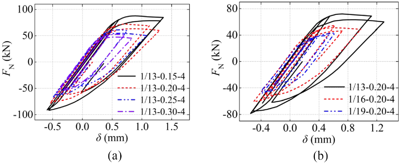
The study found that local instability deformation occurs in the transverse brace at the arch vault when the steel twin arch ribs with box-section reach the ultimate strength (Figure 11(b)). For this reason, the stress contour and deformation of the transverse brace at the arch vault were investigated when the maximum compression deformation is reached from the models with the width-span ratio b/L = 1/13, the rise-span ratio f/L = 0.20, and the angle of inclination α of 0°, 2°, 4°, 6°, 8°, and 10° (Figure 15). The corresponding axial force-displacement hysteretic curves of the transverse brace at the arch vault are shown in Figure 16.

Stress contour and deformation of a transverse brace under maximum compression (b/L = 1/13, f/L = 0.20): (a) α = 0°, (b) α = 2°, (c) α = 4°, (d) α = 6°, (e) α = 8°, and (f) α = 10°.

Axial force-axial relative displacement hysteretic curves of transverse brace (b/L = 1/13, f/L = 0.20): (a) α = 0°, (b) α = 2°, (c) α = 4°, (d) α = 6°, (e) α = 8°, and (f) α = 10°
Figure 15(a) and (b) show the stress contour and deformation of the transverse brace of the models with α of 0° and 2°, respectively. From the graphs, the maximum stress on the transverse brace at α = 0° is 364 MPa, and that at α = 2° is 373 MPa, both of which exceed the yield strength of steel of 354 MPa, indicating that the transverse brace has entered the elastic-plastic state, but no visible local buckling occurs. From Figure 16(a) and (b), the axial force-axial relative displacement hysteretic curves of the two models show that with the increase of relative axial displacement, the transverse brace transitions from the elastic stage to the elastic-plastic stage, and the growth rate of the axial force slows. In the case of the transverse brace axial force of α = 0° and α = 2° models reach 62.73, and 69.05 kN, respectively, the compression and tension show a symmetrical state, however, the steel box-section twin arch ribs fail.
Figure 15(c)–(f) indicate the stress contour of the transverse brace at the arch vault from the models with α = 4°, 6°, 8°, and 10°, respectively. The figures show that local buckling occurs in the upper flange of the transverse brace, and the instability deformation increases with increasing α; however, the maximum stress on the transverse brace of four models is about 380 MPa (changing little). In addition, from the axial force-relative displacement hysteretic curves of the transverse brace (Figure 16(c)–(f)), the transverse brace is mainly in the elastic stage when in tension, on the contrary, it reaches an elasto-plastic state when in compression, and the axial force increases slowly with the increase of displacement. When the axial force reaches a maximum strength, local instability occurs in the transverse brace and the strength reduces. When the hysteresis of the transverse brace reaches the third loop, steel box-section twin arch ribs fails.
Influences of f/L and b/L on the axial force-relative displacement curve of the transverse brace at the arch vault
Figure 17 shows the axial force-axial relative displacement curve of the transverse brace at the arch vault of steel twin arch ribs for cases of the angle of inclination α of 4° with different rise-span ratios f/L and width-span ratios b/L. As shown, the transverse brace is in its elastic stage when in tension. With the increase of displacement in compression, the structure enters its elasto-plastic stage and the axial force increases slowly. After reaching the maximum axial force, local instability deformation occurs in the transverse brace and the strength decreases slowly. The comparison of the hysteretic curve shows that the initial stiffness of the transverse brace is similar regardless of changes in the rise-span ratio and width-span ratio. With the increase of the rise-span ratio or the decrease of the width-span ratio, the yield axial force and maximum axial force of the transverse brace become smaller, which is mainly due to the rigid connection between the transverse brace at the arch vault and the arch ribs. The transverse brace bears not only the axial force but also the bending moment, and the bending moment on the transverse brace increases with the increase of the rise-span ratio or the decrease in the width-span ratio. The ultimate strength and the maximum axial force of the transverse brace at the arch vault of 72 steel box-section twin arch rib models are summarized (Table 5).
Axial force-axial relative displacement of the transverse brace of a vault when the angle of inclination α = 4°: (a) effect of the rise-span ratio and (b) effect of the width-span ratio.
Conclusion
FE analysis was used to investigate the influences of three parameters, including angle of inclination of arch ribs, the rise-span ratio, and width-span ratio, on the cyclic properties of steel box-section twin arch ribs under horizontal cyclic load. The main conclusions are as follows:
(1) The analytical results arising from the FE model established in this paper are close to previous test results. The adopted element type, mesh size, and material constitutive relationship can be considered reasonable and effective.
(2) Under out-of-plane horizontal cyclic loading, the inclination angle of the arch rib and the span-to-rise ratio may influence the yielding sequence of the components. When the inclination angle is 0° or 2°, the arch rib always yields first. However, as the inclination angle exceeds 2°, the transverse braces of arch bridges with larger span-to-rise ratios will yield prior to the arch rib.
(3) Under out-of-plane horizontal cyclic loading, with the increase in the angle of inclination of the arch ribs, the initial stiffness and ultimate strength of steel box-section twin arch ribs are improved. The internal force of the transverse brace also increases, which results in local instability and affects the strength of the whole structure.
(4) Under out-of-plane horizontal cyclic loading, with the increase in the width-span ratio or the decrease of the rise-span ratio, the initial stiffness and ultimate strength of the steel box-section twin arch ribs have been increased significantly. The axial yield force and maximum axial force of the transverse brace still decrease. The transverse brace undergoes bending in addition to the compression/extension under axial load, mainly due to the rigid connection between the brace and the two sides of the arch ribs.
Footnotes
Handling Editor: Aarthy Esakkiappan
Declaration of conflicting interests
The author(s) declared no potential conflicts of interest with respect to the research, authorship, and/or publication of this article.
Funding
The author disclosed receipt of the following financial support for the research, authorship, and/or publication of this article: The research was supported from the State Key Program of National Natural Science Foundation of China (No. 51938009), Shenyang Bureau of Science and Technology Project (23-407-3-18). The writers thank the funding body for their support.