
Abstract
A new configuration of a 9-degree-of-freedom (DOF) robot has been designed to address the prevalence of balance disorders in patients and the increasing demand for exercise rehabilitation training. This lower-limb end rehabilitation robot can assist patients with repetitive movements to stimulate and rebuild their nervous system and improve their pelvic and muscle motion control abilities. Starting from functional requirements, multiple robot configuration design schemes are proposed, and various performance indicators are comprehensively considered to ultimately select and optimize a 9-DOF redundant series-parallel hybrid robot and complete its kinematic analysis and derivation. This robot consists of a 6-DOF vestibular parallel device and a 3-DOF proprioceptive parallel device in series, which are modular in structure and function while retaining the advantages of the strong load-bearing capacity of series robots and the large workspace of parallel robots. A new structural form is proposed for investigating lower-limb rehabilitation robots.
Keywords
Introduction
With the aging of the population, the increases in the incidence of stroke and frequent traffic accidents, motor dysfunction caused by balance disorders have increasingly become a focus of social attention. 1 At present, the main rehabilitation method for patients with balance disorders is exercise training. Patients can repeat different targeted exercises, stimulate the central nervous system to actively guide brain integration, and enhance motor abilities in various muscles and joints.2,3 However, traditional physical therapy is limited by the allocation of medical resources and the degree of personalized treatment. The emergence of robots for lower limb rehabilitation training has led to revolutionary changes in this field.
Two main types of rehabilitation robots exist for balance disorders: exoskeleton robots and end-effector robots. Exoskeleton robots are installed on the outside of the user’s limbs to provide physical assistance. REX is a lower limb exoskeleton rehabilitation robot with self-balancing ability, as shown in Figure 1(a), which provides external support for users and assists them in standing. The user joystick controls REX movement. Su et al. combined brain-computer interface technology with REX and used EEG to control REX movement. 4 ReWalk is a wearable lower limb exoskeleton device that incorporates crutches, as shown in Figure 1(b). When in use, the user’s hands are supported by crutches. When the user attempts to take a step, and the sensor detection data at ReWalk’s joints drive the exoskeleton’s movement through actuators, simulating natural human leg movement, driving stroke survivor movement. 5

Current rehabilitation training robots: (a) REX, (b) ReWalk, (c) GTI, (d) GURR, and (e) Haptic Walker.
The end-effector robot drives the user’s lower limbs to complete various gait training tasks by controlling pedals or treadmills. 2 The gait trainer (GTI) is a pedal-type gait training robot developed by Stefan Hesse in Germany. Its transmission mechanism consists of an electric motor, a planetary gear reducer, and a crank rocker mechanism, which can generate elliptical motion with certain regularity to simulate the gait trajectory of the human foot during walking. However, the training requirements of different patients cannot be met because of its single training mode. 6 Figure 1(c) shows the GTI robot. Imani and Najafi researched the Guilan University rehabilitation robot (GURR). The configuration structure of the GURR includes a 2-degree-of-freedom (DOF) manipulator (orthosis) and a parallel 3-DOF manipulator (programmable plate), as shown in Figure 1(d). Each of these five actuators is driven by a ball screw along with a servo motor. 7 Haptic Walker, developed by the Swiss company Reha Technology AG, can achieve any movement. It can be seen as a redesign and improvement of GTI robots. 8 Figure 1(e) shows the Haptic Walker robot.
However, improvement of existing robot technologies is still needed in terms of applicability and training effectiveness. Exoskeleton robots are highly complex and interdisciplinary, with research difficulties, costs, and safety issues; thus, they are not suitable for patients with severe balance disorders. End-effector rehabilitation training robots often adopt parallel configurations, which may limit their movement space and functionality. Configuration design is a crucial step in robot development that directly affects the performance, reliability, and competitiveness of robots.9,10 The design of lower limb end rehabilitation robot configurations will be the focus of this work to enrich the types of rehabilitation robot products and improve the performance of rehabilitation robots, ultimately providing a new approach to the development of rehabilitation robot products.
The remainder of the paper is as follows. (1) Introduction to the human motion perception mechanism. (2) Design and comparative optimization of the rehabilitation training robot configuration scheme. (3) Kinematic modeling and simulation and workspace analysis. (4) Summary and overview of innovative points in the work.
Motion perception system
Vestibular sensation and proprioception
The vestibule is located in the labyrinth of the inner ear and is an important organ for sensing balance changes. The vestibule perceives the changes in the head angle and acceleration, inputs the characteristics of the human body’s balance state into the central nervous system, and triggers vestibular sensation. Rotational or linear movements can stimulate sensory cells in vestibular organs. The nerve impulses caused by these stimuli are transmitted to the central nervous system through the vestibular branch, where they cause corresponding sensations. 11
Proprioception refers to the proprioceptive receptors distributed throughout the human body, including muscles, joints, and ligaments. For example, the sensations of the human body due to the states such as muscle stretching and ligament pulling caused by exercise are proprioceptive. During walking, mountaineering, rock climbing, or other activities, the proprioceptive receptors transmit pressure and tension information to the brain, resulting in proprioception and completing the perception of movement. 12
Causes of balance disorders and principles of rehabilitation training
Multiple organs related to motion and perception are involved in the process of exercise and balance maintenance. Sensation is the foundation of motion, and vestibular organs and various proprioceptive receptors capture motion information and transmit it to the brain. The central nervous system analyzes and integrates sensory information and issues motor commands. Damage or degeneration of the central nervous system can lead to gait abnormalities. Maintaining balance requires sufficient muscle strength, and normal exercise also requires coordination between various joints and muscles.13,14
A decrease in muscle strength caused by aging, functional degradation of sensory organs or the central nervous system or damage to motor joints or muscles are possible factors that lead to balance disorders. For most types of balance disorders, exercise training is effective for rehabilitation. Patients can continuously practice repeated exercises to maintain a normal balance perception in the brain center, promote brain plasticity rehabilitation, improve lower limb and pelvic muscle strength and muscle control ability, and improve different types of balance disorders.
Overall scheme design and optimization
Functional positioning and performance indicators of rehabilitation robots
Functional positioning
The primary function of lower-limb rehabilitation training devices is to assist in motor training; therefore, the devices must be able to provide assistance to most types of patients with balance disorders, thereby solving the problem of single rehabilitation methods in clinical practice. In addition, real-time data regarding user posture can be collected through posture sensors or plantar pressure sensors fixed to the patient’s body, and secondary development of functions such as motion intention prediction, active training, and gait recognition can be implemented in the future.
Performance indicators
To achieve multiple daily movement modes, lower-limb rehabilitation training robots require at least 5 DOFs. Among these, three translational DOFs achieve foot translational motion, and two rotational DOFs simulate plantar flexion/dorsiflexion and inversion/eversion movements of the ankle joint. The robot also requires sufficient movement range and the ability to achieve high acceleration movements. Motion platforms must not only assist users in exercising but also support them; thus, these platforms must have a certain degree of stiffness and load-bearing capacity.
Based on the abovementioned performance indicators, various alternative configuration schemes have been proposed for structural design in the following. Considering the performance of each indicator, the best scheme is selected and optimized. Based on the optimal configuration, a research and development effort is carried out to ultimately develop a rehabilitation training robot system. Figure 2 shows the overall design process of this rehabilitation training robot.
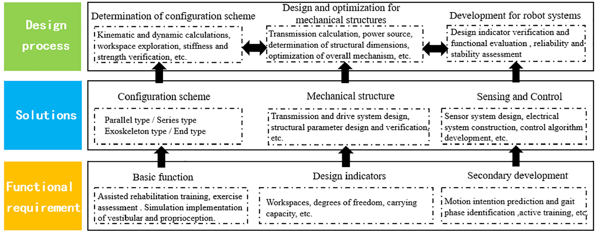
Overall design process of rehabilitation training robots.
Parallel robot configuration
Compared with more mature traditional series robotic arms, parallel robots have smaller workspaces and poorer flexibility. 15 However, these robots have significant advantages in other aspects, and a comparison of the performance characteristics of series and parallel robots is shown in Table 1.

Due to their strong load-bearing capacity, high stiffness, and low inertia, parallel robots are more suitable for application in rehabilitation training. To support training for patients with balance disorders, rehabilitation robots must have good stiffness and load-bearing capacity. Therefore, to meet the motion and power requirements, a parallel configuration was used as the original design configuration. Through homomorphic transformation and innovative and optimized design, a mechanism with a simple structure, a short transmission chain, good motion performance, and a larger workspace can be obtained, subsequently providing a foundation for the mechanical design and system development of rehabilitation robots.18,19
Configuration Scheme 1
Consider using two sets of 6-prismatic-joint-spherical-joint-spherical-joint (6-PSS) parallel mechanisms. The transmission device adopts a combination of three parallel guide rails and six sliders, with the guide rail and sliders serving as active linear motion pairs. Two motion platforms each provide support for the user’s two lower limbs. The motion platform is connected to the slider through six nonretractable connecting rods (6-PSS branch chains). One end of each connecting rod is connected to the motion platform through a spherical joint, and the other end is connected to the base through another spherical joint and a prismatic joint. Figure 3 shows a schematic diagram of the structure of the device designed according to Scheme 1.

A schematic diagram of the structure of Scheme 1.
Configuration Scheme 2
Scheme 2 is based on the traditional Stewart platform. The Stewart platform was proposed by the German physicist D. Stewart in 1965; this platform has 6 DOFs and the advantages of strong load-bearing capacity and stability, as shown in Figure 4. The Stewart platform was originally used for flight simulation; however, currently, it is the most popular parallel robot and is widely used for motion simulation in various scenarios.20,21 Although the Stewart platform is a mainstream motion simulation platform, a high platform height during rehabilitation training can cause psychological fear among users. Moreover, its workspace is small, and its motion performance is poor.
The traditional Stewart platform.
Therefore, an improved Stewart platform for configuration transformation is proposed. Six sets of sliders serve as active linear motion joints. Motion and power are transmitted to the motion platform through six motion branch chains. Each motion branch chain consists of two spherical joints and a nonretractable connecting rod. The power source drives the slider to perform one-dimensional vertical sliding. The motion platform was inverted to lower its height. Figure 5 shows a schematic diagram of the improved Stewart platform structure.
A schematic diagram of the structure of Scheme 2.
Configuration Scheme 3
The configuration design of the rehabilitation robot in Scheme 3 is also based on the Stewart platform. The Stewart platform has high stiffness and strong load-bearing capacity, but its workspace is small, and its motion performance is poor. Motion redundancy can effectively increase the flexibility of robots, avoid obstacles, and improve motion performance; however, the mechanism structure becomes more complex, and the rigidity decreases. The Stewart platform is a 6-DOF platform with full spatial positioning capabilities. Based on this platform, an additional device is added to improve the overall workspace of the robot, optimize the driving torque, and avoid internal singular configurations. The Stewart platform must not only leverage its ability to achieve 6-DOF motion but also serve as an installation benchmark for the expanded device and its support known as the lower platform. The expanded device introduces redundant degrees of freedom and increases the workspace of the robot. One end of the expanded device is connected to the lower platform, and the motion pedals at the other end drive the user to move. The expanded device is called the upper platform. The upper and lower platforms move together and cooperate, transmitting motion and power to the motion pedals of the upper platform, ultimately assisting the user in completing rehabilitation training. The upper platform can be designed as a 3-DOF linear module with a simple structure, light body weight, and fast monomer motion speed. Figure 6 shows a schematic diagram of the structure of the device in Scheme 3.

A schematic diagram of the structure of Scheme 3.
Configuration Scheme 4
The configuration of the rehabilitation robot in Scheme 4 is identical to that in Scheme 1, and two sets of 6-PSS parallel mechanisms are symmetrically arranged and used together. However, the layout of the motion platform is different, with a change in the installation direction of the motion pedal that supports the user’s feet. Six linear pairs are arranged in the same vertical plane and divided into three groups (each group at the same height), and the three groups are parallel to each other. The advantage of this approach is that the platform height is reduced, and the speed of the moving platform can be more easily achieved. Figure 7 shows a schematic diagram of the structure of Scheme 4.
A schematic diagram of the structure of Scheme 4.
Determination and optimization of configuration schemes
Comparison of configuration plans and determination of the best configuration
The device structure in Scheme 1 is compact. Due to the limited foot span of the user, to ensure that the user can stand comfortably on the platform, it is necessary to limit the distance between the two motion platforms. This results in a certain deviation of the motion platform from the base. At this point, the motion platforms must not only support the user’s gravity but also overcome the large overturning torque, adding a great burden to the power source. The traditional parallel Stewart platform is the mainstream platform for motion simulation and has a strong load-bearing capacity; however, high acceleration motion is difficult to achieve, and the platform height is large.
For the improved Stewart platform in Scheme 2, although the height of the motion platform decreased, the platform is prone to interference between the lower limbs of the user and the platform during exercise, resulting in increased safety.
Scheme 3 adopts a redundant structure design with two platforms connected in series. The lower platform has the advantages of high stiffness and large load, while the upper platform expands the workspace of the robot and improves its motion performance. However, redundant structural design also makes the structure complex and reduces the rigidity. The externally embedded connection method between the upper and lower platform increases the platform height and is unfriendly to users.
The device in Scheme 4 retains the advantages of high stiffness and strong load-bearing capacity of traditional Stewart parallel robots. This approach significantly reduces the platform height and is more suitable for application in rehabilitation training. The transmission device adopts a guide rail slider method to overcome the difficulty in achieving high acceleration motion. The movement of the motion platform horizontally along the guide rail is equivalent to direct drive and has high transmission efficiency.
Based on theoretical calculations and kinematic and dynamic simulation analysis, taking into account indicators such as workspace, kinematic performance, acceleration, and considering factors such as height of the motion platform, safety, and economic costs, the optimal configuration for the robot was ultimately determined as Plan 4.
Configuration optimization
The 6-DOF parallel robot in configuration scheme 4 has a strong load-bearing capacity, can easily achieve high-speed motion, and has a low platform height. However, this robot also has drawbacks such as a limited workspace and poor flexibility. Moreover, when completing foot inversion/eversion movements, the lower limbs are prone to interfere with the robot. To expand the workspace of rehabilitation robots and better simulate various motion modes, a redundant design method with multiple DOFs is adopted. A 3-DOF parallel robot is connected in series with the 6-DOF parallel robot, obtaining a redundant robot device with 9 DOFs. Therefore, the workspace is increased, the robot’s motion and dynamic characteristics are improved, and its operability is enhanced. The embedded connection between the two devices can effectively reduce the height of the motion platform.
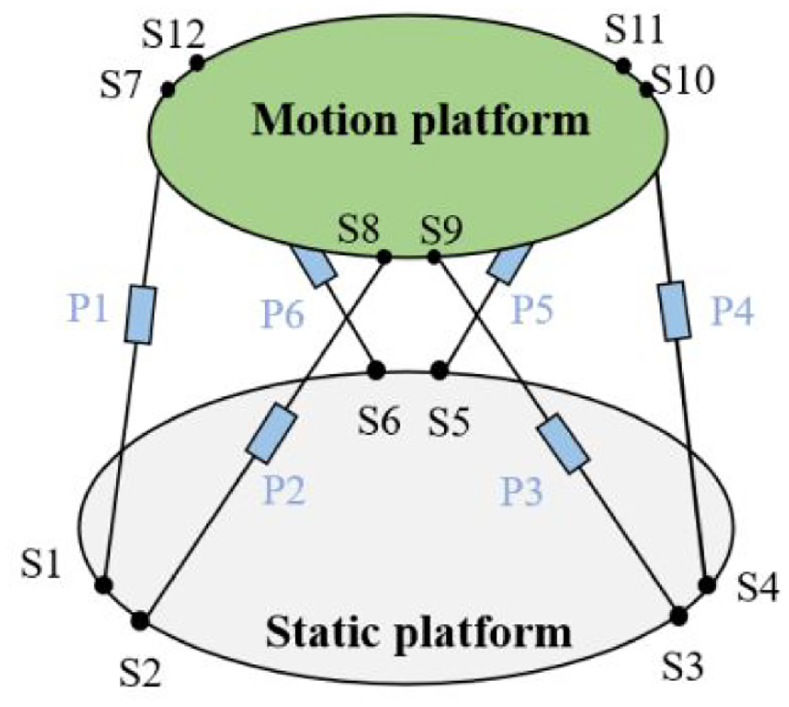
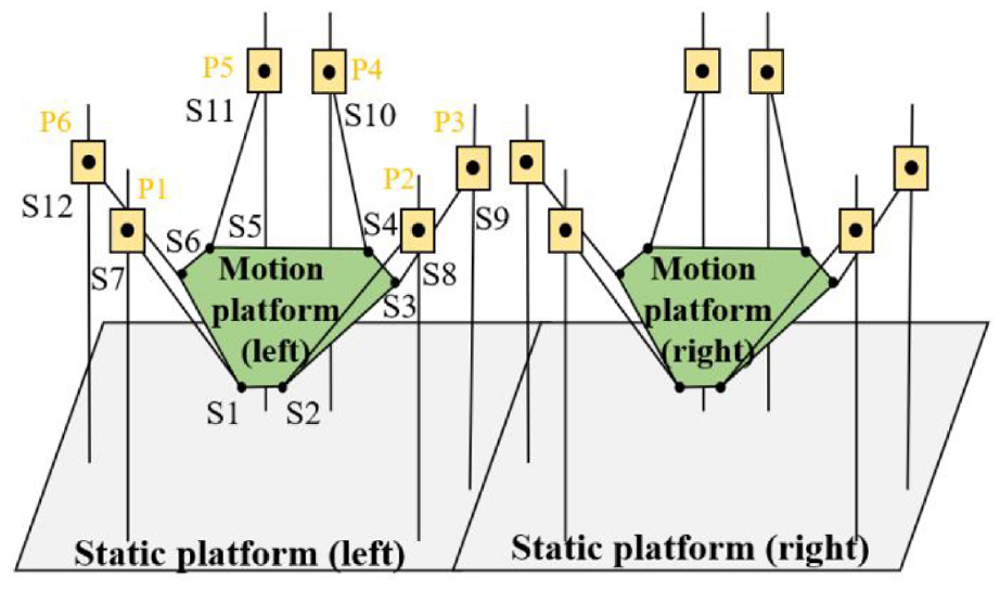
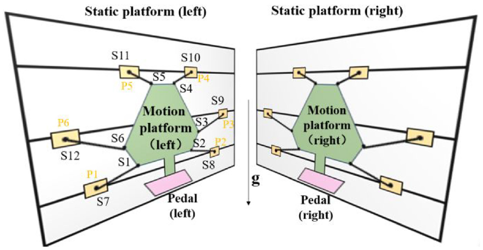
The 6-DOF parallel robot mainly simulates vestibular perception and is referred to as the vestibular device. This device can control the vestibular platform to return to the original position of movement without increasing awareness of the user, thereby providing continuous vestibular motion sensations to the user without exceeding the device’s movement range. A 3-DOF parallel robot, which is called a proprioceptive device, is used mainly to simulate proprioception. The vestibular and proprioceptive perception devices are connected in series and cooperate with each other. Decoupling of DOFs and rapid response can be achieved by reasonably allocating the DOFs between the two devices based on the motion mode. The structural diagrams of the vestibular and proprioception devices are shown in Figure 8. Table 2 shows the DOF of the vestibular and proprioception devices.
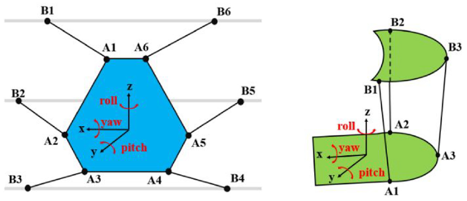
Structural diagram of the vestibular (left) and propriocetional devices. 11
DOF of vestibular and propriocetion devices. 11

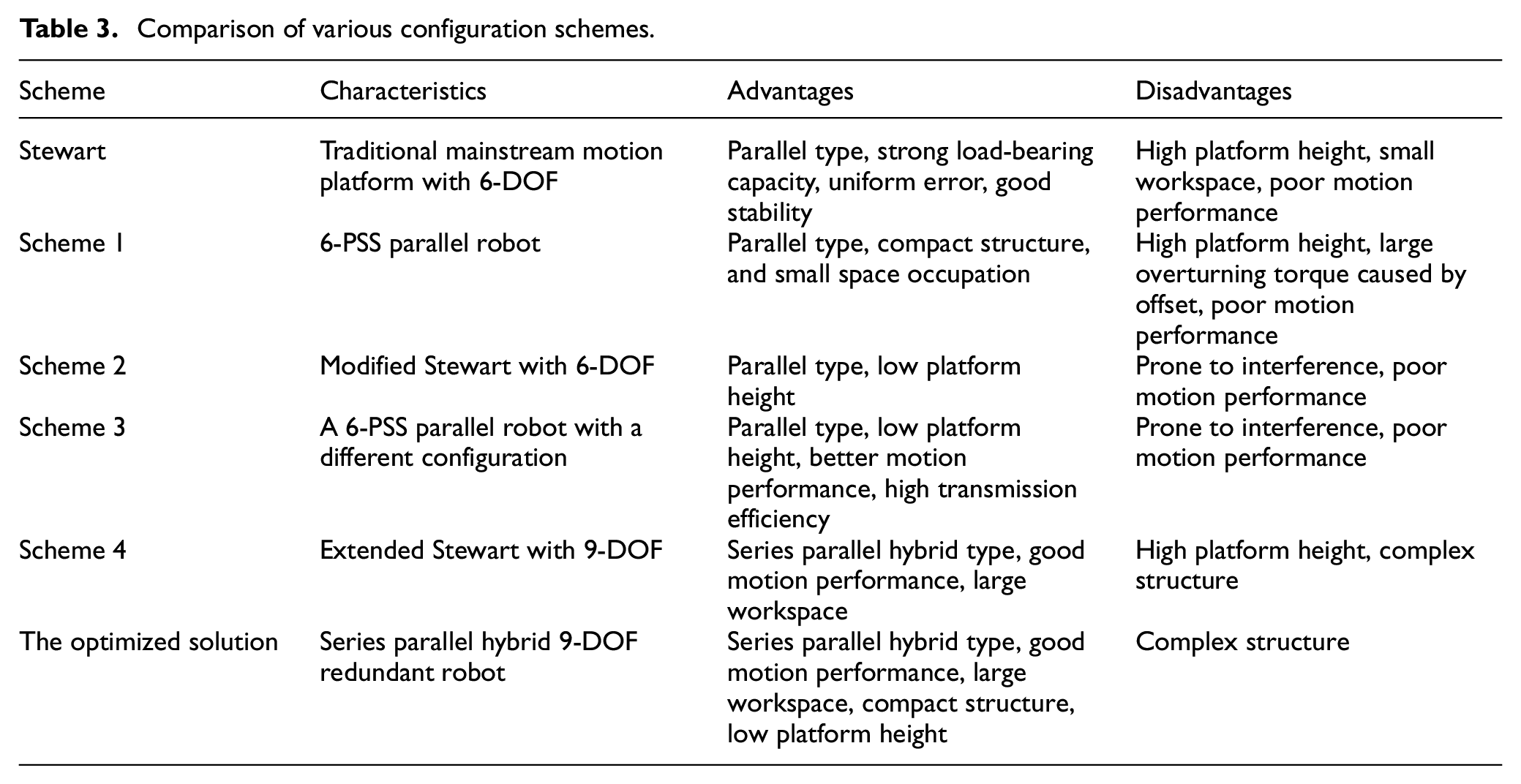
A comparison of the various configuration schemes is presented in Table 3.
Comparison of various configuration schemes.
Vestibular device
The 6-DOF vestibular platform is mainly composed of linear joints and spherical wrists. The linear joints mainly complete one-dimensional sliding in the horizontal direction. The motion and power of the linear joints are transmitted to the end motion platform through connecting rods and spherical wrists. A mechanical interface with a proprioception platform on the end motion platform serves as the installation benchmark for the proprioception platform. Three AC servo motors with fast response and high control accuracy are used as the driving components. This approach can reduce structural complexity, shorten transmission chains, reduce costs, and meet the requirements of high-acceleration motion. Due to the less strict requirements for position control accuracy, the transmission mode can be selected as a belt transmission with low cost, high elasticity and flexibility and is suitable for large shaft spacings. 11
Proprioceptive device
The 3-DOF proprioceptive platform adopts a 3-RPS parallel configuration. Two rotational DOFs and one vertical DOF can be achieved. These two rotational DOFs include inversion/eversion and toe flexion/back flexion. Three AC motors are chosen for the driving components. High-precision electric cylinders that can easily achieve high-speed motion are used as transmission components. One side of the proprioceptive platform is connected to the vestibular end movement platform through a mechanical interface, while the other side is equipped with a foot pedal. The user stands on the pedal with the assistance of suspension and other devices. 11
The 6-SSP vestibular device and the 3-RPS proprioceptive device are connected in series to form the rehabilitation robot body. This body combines weight reduction suspension devices, support and protection frames, safety shells, mechanical hard limits, and software components to form a rehabilitation training robot system. The unilateral assembly model of this robot is shown in Figure 9.

The unilateral assembly model of the robot.
The motion characteristics of robots are important indicators of robot performance, and the structural size parameters of robots directly determine their motion characteristics. Considering the constraints of the mechanical structural parameters, a parameter optimization objective function based on robot dynamics is constructed. The optimization objective function is solved using the genetic algorithm method, and the optimal structural parameters are iteratively obtained.11,22,23,26 Based on the optimization results of the structural parameters, the final structural design of the robot body is completed. In the completed passive training of patients, the control type of the robot is trajectory tracking motion control, and a control method combining the classical proportional–integral–derivative (PID) algorithm with the washout algorithm is adopted.11,24–26 Figure 10 shows a physical image of the rehabilitation training robot. The overall size of the robot system is approximately 3000 mm × 4000 mm × 2400 mm. The main materials used for machined parts are stainless steel and aluminum. The weight of the motion platform is approximately 30 kg, and the weight of the proprioceptive device is approximately 50 kg. During the operation of the robot, the safety of the user is ensured through various methods, such as weight reduction suspension devices, safety handrails, software and hardware limits, and emergency brake switches.

Photograph of the rehabilitation training robot.
Establishment of the kinematic model
The unilateral rehabilitation robot consists of a 6-SSP vestibular device and a 3-RPS proprioceptive device. This paper establishes a complementary method for allocating DOFs between two devices, thereby deriving a kinematic model of a 9-DOF redundant robot and ensuring the uniqueness of the solution. The vestibular device utilizes three translational DOFs to easily achieve high-acceleration motion in a straight-line direction. The proprioceptive device can achieve a larger and more flexible range of rotational motion, utilizing the rotational DOFs of the proprioceptive device. Due to the large range of motion of the feet in the direction of gravity (z-direction) during human movement, z-direction motion is provided by two devices that are distributed proportionally. By fully utilizing the motion advantages of two device modules with different DOFs, the robot’s motion range is significantly increased, and its flexibility and motion performance is improved.
Based on the characteristics of this 6-SSP + 3-RPS hybrid mechanism, the position analysis of the redundant mechanism can be decomposed into two parts: the position inverse solution of the 6-SSP device and the position inverse solution of the 3-RPS device. A global coordinate system

The definitions of coordinate systems.
For the 6-SSP parallel device, let the coordinates of the motion platform in the global coordinate system be

The coordinates of the six ball-joint points on the moving platform in the coordinate system

Given that the distance between the guide rails is D and the length of the connecting rod is
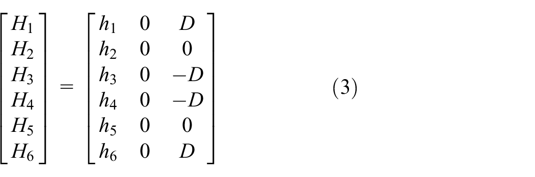
A closed vector equation is established for the i-th branch is shown in Formula 4:

The inverse solution model for the position mapping of the 6-SSP mechanism can be obtained as follows:

The inverse solution model of this position establishes the pose of the motion platform
For 3-RPS parallel mechanisms, let the pose of the motion pedal, which is fixedly connected to the tool coordinate system

If the coordinates of three hinge points on a static platform in the local coordinate system

If the coordinates of the three hinge points on the sports pedal in the tool coordinate system

If the coordinates of the three hinge points on the sports pedal in the local coordinate system

If the length of three electric cylinders is

The position mapping of the 6-SSP and 3-RPS redundant hybrid mechanisms are programmed. Four sets of inverse kinematics solution results are visually displayed. Table 4 shows the four poses of the 6-SSP device and the 3-RPS parallel device, and Table 5 shows the corresponding inverse position mapping solutions. Figure 12 shows the visualization of four sets of inverse solutions for position mapping.
Four poses of 6-SSP device and 3-RPS parallel device.

Four corresponding inverse solutions for position mapping.


Visualization of four sets of kinematic results for the robot: (a) the first set of kinematic solution, (b) the second set of kinematic solution, (c) the third set of kinematic solution, and (d) the fourth set of kinematic solution.
The workspace of the robot was explored based on kinematics. Compared with that of the 6-SSP robot, the redundant structure of the 9-DOF robot significantly improves the workspace. The larger the workspace is, the more motion modes the robot can complete, the larger the range of motion, the more realistic the somatosensory simulation, and the better the training effect. The workspaces of the 6-SSP parallel mechanism, 3-RPS parallel mechanism, and their hybrid mechanism are shown in Table 6.
Workspaces of the three mechanisms.

The theoretical reachable workspace of the 6-SSP device is infinite in the x-axis direction, from 0 to 700 mm and from −24° to 24° in the y-axis direction, from −250 to 250 mm and from −6° to 6° in the z-axis direction, and from −26° to 13° in the x-axis direction. The reachable workspace of the 3RPS parallel mechanism ranges from −150 to 150 mm in the z-axis direction, from −26° to 26° in the x-axis direction, and from −26° to 26° in the y-axis direction. The introduction of 3-RPS has increased the complexity of the structure, but it has also significantly increased the workspace, improving the motion and dynamic performance, operability, and flexibility of the mechanism. The workspace range of redundant mechanisms far exceeds the travel range of gait training, such as walking. By combining the traversal calculation of the Jacobian matrix and kinematic and dynamic simulation methods, the robot is ensured to have no singular points in a reasonable workspace.
Conclusion
Starting from configuration design and optimization, with balance-disorder rehabilitation training as the core function, a layer-by-layer, interweaving forward–reverse direction design was advanced, ultimately providing a new structure for the development of rehabilitation robot products. Multiple alternative configuration schemes were proposed, accounting for various performance indicators, and ultimately optimized to obtain a lower-limb rehabilitation training robot that integrates proprioception and vestibular somatosensory simulation. This robot adopts a series-parallel hybrid 9-DOF redundant structure, which combines the advantages of parallel and series robots. This rehabilitation robot can achieve smooth and vibration-free movement during operation and can assist users in completing various motion training modes. Compared with other end effector rehabilitation platforms, the redundant design of DOF increases the robot’s workspace and improves its motion performance. At a functional level, this device can be divided into vestibular modules and proprioceptive modules based on its structure. Independent or coupled control of two modules is implemented as needed to achieve multibody sensing simulation. By employing a reasonable DOF allocation and complementary approach, the kinematic model of the redundant robot was established and analyzed, and the uniqueness of the kinematic solution was achieved, ensuring that the robot can accurately and reliably achieve the desired motion and provide accurate position and attitude information for use by the control system.
The main innovation points are summarized as follows:
(1) Multiple configuration schemes were proposed, and through simulation analysis, theoretical calculations, and comparative optimization, a 9-DOF structural form combining the advantages of various configurations was ultimately obtained. Redundant structure design can effectively avoid interference between users and platforms, increase the workspace of robots, and improve the motion performance and operability of robots.
(2) The vestibular platform transmission mechanism adopts a parallel guide rail form, which easily achieves high-acceleration motion and has the advantages of a low platform height and a high effective load ratio. The embedded connection between the vestibular platform and the proprioceptive platform can further reduce the platform height.
(3) Rehabilitation robots are divided into two modular units at the structural and functional levels. In terms of structure, modular vestibule device and proprioceptive device can be assembled and disassembled. Two functional modules can be coupled or decoupled to achieve complex motion patterns and complete multibody simulation. The complementarity principle and allocation of DOFs between two modular devices and a kinematic model of the 9-DOF redundant robot were established.
Footnotes
Handling Editor: Aarthy Esakkiappan
Declaration of conflicting interests
The author(s) declared no potential conflicts of interest with respect to the research, authorship, and/or publication of this article.
Funding
The author(s) received no financial support for the research, authorship, and/or publication of this article.