
Abstract
A novel coupled wheel/track mechanism is proposed to overcome the complexity and limited applicability of conventional coupled wheel/track robots. The mechanism is based on the design of a tracked off-road robot, where the track is separated from the driving wheel and the load-bearing wheel by a fork fixed on the frame. The tension-wheel compensates for the shortening of the track winding length by moving along the frame. The chain transmission between the first pair of load-bearing wheels and the driving wheel enables the wheeled operation. The coupling mechanism is characterized by only one set of walking mechanism, and the coupling is realized by separating part of the walking mechanism, avoiding the use of the clutch. The advantages of this mechanism are its simple and reliable structure, low cost, and easy installation of the suspension system. A simulation experiment is conducted to verify the performance of the mechanism, and a prototype is designed and manufactured for testing. The structure was used to design simulation experiments, and a test model of the vehicle was designed and fabricated. The design specifications were achieved by the results.
Keywords
Introduction
As intelligent technology advances, off-road robots are becoming an increasingly important part of inspection, counter terrorism, and reconnaissance. Tracked off-road robots,1–5 as an indispensable type of off-road robot, have received widespread attention. However, due to the characteristics of the track structure: large mass under the suspension spring and large driving resistance, it is difficult to run at high speed, limiting the use of tracked off-road robots.
Multi-walking mechanism, as a new type of special robot chassis structure, can flexibly switch between multiple required walking mechanisms compared with traditional single-walking mechanism chassis. It can have both the fast energy-saving performance of wheeled and the high obstacle-crossing performance of tracked. Therefore, coupled wheel/track robots have become the research object of many scholars.6–12 Unlike wheel-track composite robots,13–15 coupled wheel/track usually only has one set of walking mechanisms. For example, based on the track structure design, using the conversion mechanism to control the overall deformation of the track into a cylindrical shape to achieve the purpose of wheeled operation; or based on wheeled design, using linkages and other mechanisms to expand the retractable track from the wheel to make the off-road robot achieve tracked operation. Therefore, the coupling structure is more compact than the composite robot with two sets of walking mechanisms and one set of conversion mechanisms.
Guo et al. 16 proposed a coupled wheel/track robot as shown in Figure 1. Jin et al.17–19 designed a coupled wheel/track robot as shown in Figure 2. However, existing coupled wheel/track off-road robots20–22 either cannot use rigid tracks or are not round enough when running on wheels. Most of their parts are complex non-standard parts with high requirements for processing technology, which makes them unable to be widely used.

The coupled wheel/track mechanism designed by Guo et al. 16

Therefore, this paper proposes a new type of coupled wheel/track mechanism. 23 This coupled wheel/track mechanism is based on tracked vehicle design and uses a stepping cylinder to drive a fork to automatically disassemble and assemble tracks to achieve coupled wheel/track effect. Not only does it simplify the structure and improve reliability, but more than 80% of the parts of the whole vehicle are general-purpose parts, which increases the applicable field of this type of special robot.
Design of coupled wheel/track transmission mechanism
General part structure design
Figures 3 and 4 depict the modeling design based on UG 3D software. Figure 4 shows the tracked state of the model prototype, which shares a similar overall framework with conventional tracked vehicles. Its walking mechanism mainly includes drive wheels, several load-bearing wheels, guide wheels, support belt wheels, forks, tracks. In addition, the drive wheel is connected to the first pair of load-bearing wheels through a chain transmission. The end of the main shaft is fixed with the drive wheel, while the hanging wheel sleeve is mounted on the main shaft and relies on thrust ball bearings to maintain its axial position with the drive wheel. The support wheel provides tension to the track using a crank and spring, with a stepper motor cylinder connected to a fork on the inside of the vehicle body, and the fork arranged at the upper rear end of the drive wheel.
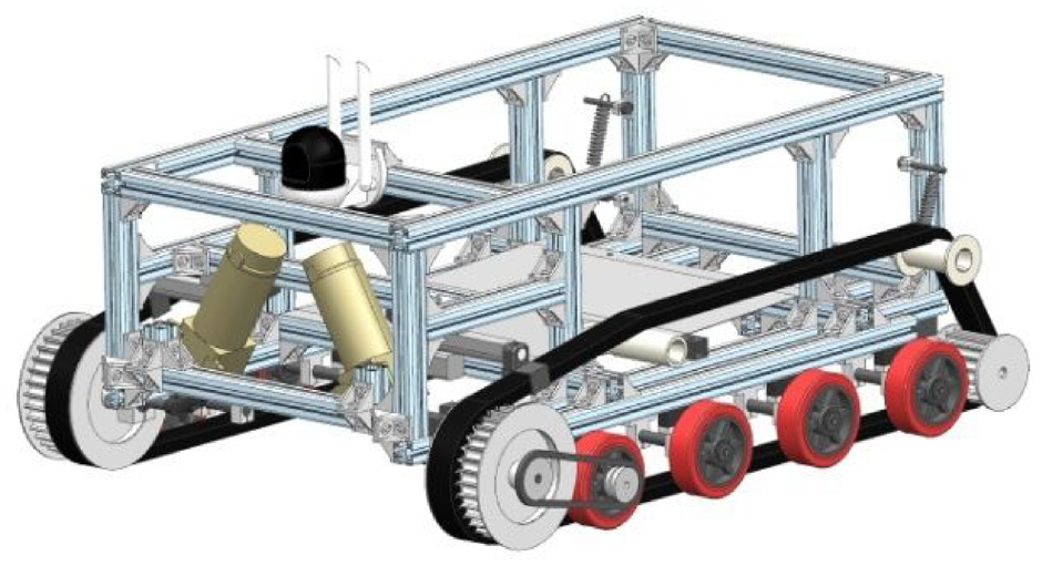
UG model of wheeled prototype vehicle.

UG model of crawler prototype vehicle.
Figure 3 shows the wheeled state of the model prototype, differing from the tracked state in that the track hangs on the hanging wheel without contact with the ground. Contact with the ground is made by four pairs of load-bearing wheels, with power transmitted from the main shaft to the first pair of load-bearing wheels through chain drive. This coupled wheel-track mechanism features a simple structure, low cost, and to some extent reduces the installation difficulties of the suspension system. Although the actual vehicle is not equipped with a long-stroke suspension system, it can be arranged with a Christie suspension like the BT series light tanks.
The track adopts a double-sided toothed belt with an arc tooth shape and a tooth pitch of 20 mm. The drive wheel and guide wheel adopt synchronous belt wheels with corresponding tooth shapes. The load-bearing wheel adopts a polyurethane rubber wheel. The support belt wheel is made by 3D printing and cushioned with foam bath pads (the synchronous belt pitch is large and the vibration is obvious). The fork is made of C-shaped steel. The chain drive between the drive wheel and the first load-bearing wheel is an 08B roller chain. The specific parameters in the model are shown in Table 1.
Main specifications of robot.

This robot has two main motors and two stepping electric cylinders. The main motor uses a 24 v 500 w DC brushed reduction motor with a reduction ratio of 3.6. The stepping electric cylinder uses DS3120 with a thrust of 240 N. The electric cylinder movement speed is 12 mm/s, and the stroke is 100 mm (the practical stroke is 56 mm). The main controller uses a stm32 series microcontroller to receive and process information sent by various units, coordinate the operation of the whole machine, generate corresponding signals after executing control algorithms and send them to devices such as DC motor drivers and stepping electric cylinder drivers to control the operation and track switching of robots. The power supply module uses a 6s lithium battery with 24 v, 40 AH, and 3-5 c, with a maximum output current of 120–200 A. It is connected to a DC motor driver through a Sepic chopper circuit for voltage stabilization to ensure that the motor can obtain reliable voltage while reducing energy loss caused by voltage stabilization. In addition, it is supplied to corresponding modules after multi-channel LDO linear voltage stabilization to other module working voltages.
Design of wheel drive route
When the robot is in wheel operation mode, the track hangs on the hanging wheel, guide wheel, and support belt wheel, and maintains a certain distance from the ground. This distance depends on the ground clearance of the hanging wheel and guide wheel. Due to the large resistance torque brought by the deformation of the track, which is much larger than the resistance torque of the thrust ball bearing between the drive wheel and the hanging wheel, the track is basically stationary during wheel operation.
Since the hanging wheel is arranged between the driving wheel and the frame with a hollow sleeve on the main shaft, when the track is dialed from the outside to the inside (i.e. when the track type is converted to the wheel type), the hanging wheel is driven by the track to rotate. The synchronous teeth on the hanging wheel can ensure that the hanging wheel and the driving wheel rotate synchronously, greatly reducing the friction and vibration of the track during wheel-track switching.
The reduction motor drives the main shaft to rotate through a coupling to achieve the operation of the drive wheel. The drive wheel relies on the chain drive arranged between it and the first pair of load-bearing wheels to drive the first pair of load-bearing wheels to provide traction. Currently, the fork is inward, and the electric cylinder is locked to maintain the lateral position of the track.
Design of crawler drive route
When the robot is in track operation mode, the track hangs on the drive wheel, load-bearing wheel, guide wheel, and support belt wheel. Currently, the track is grounded and uses the operation of the drive wheel to provide traction. At the same time, the drive wheel is still connected to the first pair of load-bearing wheels through a transmission chain, so it is necessary to maintain the transmission ratio between the drive sprocket and the driven sprocket approximately inversely proportional to the pitch circle diameter of the drive wheel and the equivalent pitch circle diameter of the load-bearing wheel:

Where i12 for the transmission ratio between the drive sprocket and the driven sprocket, R1 for the radius of the pitch circle of the drive wheel, which is 105 mm in the prototype, R2 for the radius of the load-bearing wheel, which is about 70 mm in the prototype.
From formula 1, the transmission ratio between the drive sprocket and driven sprocket in the prototype is about 0.7 (Slightly less than or slightly more than the actual value will help with tensioning), which can avoid excessive wear on the first pair of load-bearing wheels. At this time, the fork is outward and the stepping electric cylinder is locked to keep the track outward.
Structure and process design of wheel-track transformation
The structure of the fork used to change the form of wheel-track travel is shown in Figure 5. To improve reliability and controllability and reduce the number of non-standard parts, a stepping electric cylinder is directly used to drive the movement of the fork. When the track is switched to wheel mode, the stepping electric cylinder drives the fork to move inward. At this time, to ensure that it will not be stuck by the hanging wheel when switching in, the edge of the hanging wheel needs to be trimmed. When switching from wheel mode to track mode, the stepping electric cylinder drives the fork to move outward. To ensure that it will not be stuck by the drive wheel when switching in, the edge of the drive wheel needs to be trimmed. Since the lower tangent line of the drive wheel is higher than the lower tangent line of the first pair of load-bearing wheels when in track mode, it is necessary to chamfer the inner side of the first pair of load-bearing wheels. The height of the chamfer should be greater than or equal to the thickness of the track (if the track has a chamfer, then the height of the chamfer required on the load-bearing wheel is equal to the thickness of the track minus the height of the chamfer on the track). In addition, considering that the fork is a stationary part relative to the robot and that the track is a moving part, the track groove on the fork needs to be wider than the width of the track. The width of the track on this prototype vehicle is 50 mm and its groove is about 56 mm. During switching, relying on rotation of drive wheel, tracks are successively switched into (disengaged from) drive wheel, load-bearing wheel, guide wheel, and support belt wheel to achieve transformation of walking form.

Schematic diagram of fork structure.
If the track is severely worn or if there is significant resistance during the wheel-track conversion process, the bend of the C-shaped steel can be sawed to a length of about 1 cm and the two side plates can be bent outward at an Angle. This will allow the track to enter the fork at an incline, effectively reducing wear and tear. If using a metal track, this incline can also help prevent significant impact.
Robot control system design
System overview
The control system of this tracked coupling off-road robot is divided into two modes: manual control and autonomous control.
Manual control uses a handheld terminal remote control device to control the robot. This handheld terminal remote control device uses a 2.4 G wireless communication module to interact with the robot. By obtaining information from the remote-control panel and converting it into a specified data packet format, and sending data according to a specified communication protocol, the robot receives the corresponding frame data and parses it according to the specified data format. Through data parsing, the robot obtains data such as running speed, running mode, and movement direction. Finally, the underlying drive is controlled accordingly through the parsed data.
Autonomous control sends the target position through a remote console. The robot locates itself through Beidou and GPS modules. It can directly send coordinates through a remote terminal and change the robot’s trajectory by controlling the motor to achieve autonomous navigation of the robot. 24 During movement, the robot corrects its posture through a six-axis sensor. The off-road robot has a camera module that can be connected to the network to return image information.
This off-road robot has two structural states: wheel and track. The wheel mode is mainly used on hard smooth ground and hard slopes; track mode is suitable for swampy ground, stairs, and urban ruins. The robot can switch between modes of travel using a stepping electric cylinder. In automatic control mode, wheel-track switching can be performed automatically based on the data obtained by the sensors. For example, in wheeled mode, if the gyroscope pitch axis acceleration is large and the encoder output signal fluctuates greatly, it indicates that the robot is on an uneven road surface such as urban ruins. At this time, it will automatically switch to tracked mode. When the encoder outputs normally and the gyroscope acceleration has small fluctuations in multiple directions and remains for a period, it indicates that the robot is on a flat road surface and can be switched to wheeled mode. When the encoder is operating normally but the gyroscope acceleration is almost zero, it indicates that the robot is in a swamp or stuck. At this time, it can be switched to tracked mode for obstacle crossing.
Hardware system
To achieve path planning, autonomous navigation, autonomous obstacle avoidance, and obstacle crossing functions, the hardware circuit modules of the tracked coupling off-road robot need to be selected and designed in combination with their functions. Reasonable hardware circuit design will provide hardware support for the movement of the off-road robot. The overall design idea of the hardware circuit of the off-road robot is shown in Figure 6, and its main module selection is as follows:
① Main controller: The main controller is the core of the robot. It uses a stm32 series microcontroller to receive and process information sent by various units, coordinate the operation of the whole machine, generate corresponding signals after executing control algorithms and send them to execution devices such as DC motors to control the operation of the robot.
② Motor and its driver: This design uses a DC motor driver with a Modbus communication protocol to communicate with the main controller, which has high expandability. The stepper motor uses a tb6612 driver module, which can control the running speed of the stepper motor by adjusting the subdivision and current.
③ Navigation system: Use a GPS module to calculate azimuth information, supplemented by angle information from a six-axis gyroscope. By continuously adjusting the actual angle of the robot through the motor to approach the target angle, navigation can be achieved.
④ Gyroscope: Use an MPU6050 six-axis sensor to control posture. The MPU6050 integrates a three-axis gyroscope and a three-axis accelerometer. Its built-in MPL library, that is, Motion Processing Library, only needs to push sensor data to MPL lib, and then MPL will process the fusion of six-axis data and calculate the current posture angle with a maximum frequency of 200 Hz. During movement, analyze the posture of the robot and link it with the encoder to determine the scene at the current location of the robot. For example, if the encoder speed fluctuates and the pitch axis of the gyroscope shakes severely, it means that there is an obstacle in the form of ruins currently. At this time, it automatically switches to track mode; when the encoder angular velocity returns to normal and the angular velocity fluctuation of the gyroscope is reduced and maintained for a certain period of time, it means that it has returned to a hard road surface and can switch back to wheel mode; for example, when entering steps or swamp terrain in wheel mode, the encoder will operate normally while the gyroscope hardly senses any angular velocity. Currently, it also needs to switch to track mode. This robot can ensure adaptability in complex scenarios through this algorithm.
⑤ SIM808 communication and Beidou/GPS module: SIM808 is a GSM+GPS+Bluetooth three-in-one combination module launched by SIMCOM. The Beidou/GPS module combines Beidou and GPS technology to obtain current latitude and longitude information. It adopts an industry standard USART interface and can easily exchange data with the main controller through USART.

Overall design idea of hardware circuit of cross-country robot.
Analysis of main bearing structure
The vehicle chassis is an important component that bears the weight and load (60 kg) of the whole vehicle, and the longitudinal beams are subjected to both bending and torsional stresses, which have a significant impact on the reliability of the robot operation. The chassis mainly consists of four load-bearing longitudinal beams, four load-bearing transverse beams, and corresponding angle codes. The chassis model is imported into Ansys software for finite element analysis. The frame adopts European standard 4040L aluminum profile. The specific parameters are shown in Table 2.
Main parameters of the material used.

A force of 100 N is applied at each end of the load-bearing axle; the mesh element size adopts the default value, and the total number of elements of the frame and load-bearing axle is 568,304, and the total number of nodes is 2,959,886, as shown in Figure 7.

Frame unit division diagram.
Finite element analysis was performed in ANSYS: Figures 8 and 9 show the stress distribution and deformation maps of the frame, respectively. Through finite element analysis, it can be seen that the maximum equivalent stress of this structure is at the intersection of the outer longitudinal beam and cross beam, with a size of about 14.33 MPa, which is much smaller than the strength limit of the material; while the maximum strain is at the shock absorber block under the bottom longitudinal beam, with a size of about 0.94 mm, which is also within the safe range.

Stress distribution diagram of car frame.

Strain distribution diagram of vehicle frame.
Analysis of robot wheel track transformation process
An analysis of the theoretical speed of wheel-track conversion based on the movement of the fork. Due to the constraints of assembly accuracy and sheet metal bending conditions, and the need for separation of moving and static parts, the design distance between the track and the fork on both sides is 3 mm, and the width of the track is 50 mm, so the width of the fork groove needs to be designed as 56 mm. The stroke required by the stepping electric cylinder is:

where L1 for the relative distance between the two poles of the track, which is 50 mm in the prototype, L2 for the single-sided gap between the track and fork during normal operation, which is 3 mm in the prototype.
From the above formula, the stroke required by the stepping electric cylinder is at least 56 mm (irrespective of the width of the fork groove).
As shown in Figure 10, when the robot just starts to move, the track is in the middle position of the fork groove, as shown in the figure 10(a). When switching from track mode to wheel mode, the stepping electric cylinder moves inward by 53 mm to the limit point of the fork, The process is shown in figure 10(b). After switching to correct position, figure 10(c), it moves back by 3 mm to separate from track during operation and make track at center position of fork groove, figure 10(d). The direction is opposite when switching from wheel mode to track mode and process is same.

Fork displacement sequence.
After switching to correct position, since completion of wheel-track switching requires track to be connected/disconnected from all load-bearing wheels, in addition to time for fork operation, time for track to move from fork to last load-bearing wheel must be added. According to data measured by prototype model, time is approximately:

where Tfork for time taken by the electric cylinder to move to the end point (excluding return time) s, V for speed at which robot moves m/s, Vfork for Speed at which electric cylinder moves, which is 12 mm/s in prototype, L for the curve distance of the track from a point of the fork to the last pair of bearing wheels, which is 1.5 m in the prototype, M for distance required to move the stepping cylinder, which is 53 mm in the prototype.
In the above formula, when V = 0, the track will jam the fork and cannot perform wheel and track change.
When robot moves at speed of 3 m/s, time for wheel-track conversion is about 5 s according to formula (3). In actual situation, when switching from wheel mode to track mode, Ttotal is slightly larger than above formula; when switching from track mode to wheel mode, Ttotal is slightly smaller than above formula. The reason is that when switching from wheel mode to track mode, first pair of load-bearing wheels need to press on track and consume a small amount of time; while when switching from track mode to wheel mode, track will slip out from under first pair of load-bearing wheels earlier.

Where Toverlap for time when robot is in overlapping state of wheel and track.
Robot kinematic model
To facilitate algorithmic control, a motion model of the robot was established. To simplify the motion model, the following assumptions were made: (1) The robot’s wheels do not produce idling when rolling; (2) The robot’s center of mass (COM) is located on the robot’s geometric longitudinal symmetry line, but not necessarily on the geometric transverse symmetry line; (3) The contact points between the robot and the ground do not move due to acceleration caused by steering or manufacturing errors.
Analysis of robot wheel kinematics model
Since this robot is driven by the first pair of load-bearing wheels in the wheel state and does not have a long-travel suspension, and the second and third pairs of load-bearing wheels are slightly higher than the first and fourth pairs of load-bearing wheels during design (to ensure the stability of the robot, if you want to make the robot more flexible when turning in the wheel state, you can use adjusting gaskets to slightly raise the third and fourth pairs of load-bearing wheels, that is, by changing the main load-bearing wheels to reduce the wheelbase during wheel operation). Therefore, only the first and fourth load-bearing wheels provide ground force when the wheel is on a hard flat surface. Although only the first pair of load-bearing wheels has power, since the fourth pair of load-bearing wheels is not a universal wheel, that is, it can provide effective lateral friction force, it should belong to a four-wheel differential model instead of a two-wheel differential model. In a four-wheel differential model, when the vehicle turns, there is inevitably lateral slippage of the wheels. Therefore, the method of simplifying and equivalently processing the motion model of a four-wheel drive mobile robot as a two-wheel differential drive robot motion model is used for analysis. 25
Since establishing a coordinate system for a four-wheel drive mobile robot has certain particularities because it realizes steering motion through sliding friction,26,27 it is necessary to consider the influence of robot mass distribution on robot motion. As shown in Figure 11, since the geometric center of the robot has no significant impact on the kinematic model, only the coordinate system X-COM-Y is established with the robot center of mass COM as the origin. The forward direction of the robot is the positive direction of the X-axis, and perpendicular to it to the left is the positive direction of the Y-axis. Points A, B, C, and D respectively represent ideal contact points between tires and ground. ICR is the center of vehicle steering. Taking ICR-COM as the horizontal axis line and CENTER-COM as the vertical axis line, assuming that virtual left and right wheel contact points with ground is located at points L and R respectively. Currently, virtual wheelbase LR length is greater than or equal to real wheelbase QP (equal when going straight and equal when turning only when center of mass happens to be on front/rear axle centerline). This virtual wheelbase LR changes dynamically. Let vl and vr represent longitudinal component velocities of left and right wheels respectively; vf and vb represent transverse component velocities of front and rear wheels respectively.

Simplified equivalent diagram of wheeled state model.
If there is no rotational motion (no slip), it means that only vl and vr exist, and both vf and vb are 0. In this case, LR = QP. However, if there is rotational motion, that is, vf and vb are not 0 and there is a slip phenomenon, the angular velocity calculated according to vl and vr and PQ is not the real angular velocity. Different rotational motions have different degrees of slip and different effects on the actual angular velocity. Therefore, the virtual wheelbase LR changes dynamically and is related to the sliding friction situation. Therefore, the contact between the ground and the tire with different friction coefficients has different effects on the actual rotation motion, so it is difficult to control accurately.
Since the virtual wheelbase LR is a parameter that changes with working conditions and cannot be obtained analytically. The method given in Wang et al. 28 introduces a dimensionless parameter γ, dLR = γdwb, that is, γ is the ratio of virtual wheelbase to actual wheelbase. This parameter is related to the total load of the robot, the relative friction coefficient between the tire and the ground, the turning radius and the position of the center of mass. It is a very complex parameter. Therefore, a commonly used method is to do experiments. The robot that is no longer changed controls differential steering motion on a specific ground. After collecting multiple sets of experimental data, γ ratio can be estimated by fitting.
Simplified forward kinematics model of robot
The simplified model of the robot in the wheel state can be transformed into a two-wheel differential model. The kinematic analysis of the two-wheel differential model can be based on the speed of the virtual left and right drive wheels to calculate the speed of the main body reference frame center, which can be expressed as:

When the robot is in the track state, the method of processing the model is like that of the robot in the wheel state. There is also slip, so it is simplified and equivalently processed as a two-wheel differential drive robot motion model, as shown in Figure 12.

Simplified equivalent diagram of crawler state model.
Simplified inverse kinematics model of robot
After the wheel and track models are equivalently processed, they are the same and can be based on the speed of the main body reference frame center to decompose the speed of the left and right drive wheels, which can be expressed as:

Robot kinematics model solving
The above problem ultimately boils down to how to find γ ratio. Since this parameter is related to the total load of the robot, the relative friction coefficient between the track and the ground, the turning radius and the position of the center of mass, it is a very complex parameter. Therefore, a commonly used method is to do experiments. Therefore, a common method is to conduct experiments, install an encoder on the active axle through chain transmission, and install a gyroscope on the control board. The tests are performed under different steering radii, which need to be given in advance. The calculation formula is:

The experimental process is shown in Figure 13. After the test is completed, the relevant data obtained in the wheel-type state are substituted into equation (8), and in the tracker-type state into equation (9).


where nR for speed measured by the robot right-wheel encoder, nL for speed measured by the robot revolver encoder, r1 for radius of bearing wheel, r2 for driving wheel pitch diameter, wC for angular velocity actually measured by the gyroscope, i1 for spindle to encoder transmission ratio, i2 for transmission ratio from spindle to first pair of bearing wheels.

Experimental flow chart.
The γ ratio to be tested in this experiment is divided into γwheel ratio for the wheel state and γtrack ratio for the track state. The test was conducted on a hard asphalt road surface. The collected data fluctuated greatly. After fitting with the trend equation in Excel and substituting it into the above formula for calculation, the calculation results are shown in Figures 14 and 15. The vertical axis is γ ratio and the horizontal axis is the turning radius.

Relation between wheeled γ ratio and steering radius.

Relation between tracked γ ratio and steering radius.
As shown in Figure 14, the function of γ ratio in the wheel state with the change of turning radius is a convex function, although it is different from the theoretical description. However, this is due to the long wheelbase of this robot and severe slip when the turning radius is small.
In Figure 15, the γ value of the track state is a concave function and tends to 1 after the turning radius reaches a certain level, indicating that the slip is not serious and conforms to the above theory.
Robot track obstacle crossing analysis
Since this robot is only suitable for flat hard surfaces in the wheel state and is not suitable for overcoming obstacles, it needs to switch to track mode when overcoming obstacles. When there is a step on the road surface, the theoretical maximum vertical obstacle height that the robot can cross is analyzed based on the center of gravity analysis.
A coordinate system X-O-Y is established at the idler wheel axis, with the vehicle’s forward direction as the positive direction of the X-axis and the vehicle’s height direction as the positive direction of the Y-axis. The radius of the load-bearing wheel is R (including track thickness), and the radius of the idler wheel is r (including track thickness). The center of mass of the robot is M (x, y), as shown in Figure 16.

Demonstration of robot crossing vertical obstacle.
To climb the steps, it is necessary to ensure that the center of gravity of the vehicle can reach the extension line of the vertical surface of the obstacle when climbing. At this time, when the robot’s pitch angle is α, the obstacle height H can be expressed as:

Taking the center of mass coordinates as variables, the derivatives of equation (10) with respect to x and y are respectively:


When α is a constant between 0° and 90°, the theoretical maximum obstacle height of the robot is Hmax. Combining equations (11) and (12), it can be seen that the theoretical maximum obstacle height increases as the center of mass decreases and as the center of mass moves forward. Therefore, the prototype is front-engine and front-driven, and the heavier driving wheel and hanging wheel are arranged in the lower front part of the robot.
According to equation (10), when the center of mass is fixed at (x0, y0), each value of α corresponds to a critical obstacle height. If the critical obstacle height increases with the increase of α, it means that the robot can successfully climb the steps; otherwise, it means that the current obstacle height is the maximum obstacle height of the robot.
The calculation formulas for the first and second derivatives of H(x0, y0, α) with respect to α are as follows:

Since when α∈(0, 0.5π), ∂2H/∂α2 < 0, H(x0, y0, α) has only one maximum value. When (∂H/∂α) = 0, Hmax exists. This means that once R, x0, and y0 are determined, α corresponding to Hmax can be obtained from equation (13), and then the maximum obstacle height of the robot can be obtained by substituting it into equation (10).
After measurement, the actual vehicle R is 90 mm, r is 75 mm, and the center of mass is M (680, 167). The calculated α is 44.976°. Through the above calculation, Hmax is 310.47 mm, which is enough to cross general urban obstacles.
In fact, since the track is not a rigid body and there is a large gap between the two load-bearing wheels (equivalent to a decrease in y0), and common vertical obstacles usually have rounded corners (equivalent to a decrease in vertical obstacle height), the actual obstacle height will be higher than the calculated value.
Test study
To verify the reliability of this structure and the simulated structure, a physical prototype vehicle was made as shown in Figures 17 to 24. The vehicle mass is about 87 kg, and the dimensions of length, width, and height are 1280 mm × 1020 mm × 515 mm respectively. To test whether the speed of wheel-track conversion has reached the expected goal, experiments were carried out in both wheel-to-track and track-to-wheel modes at a speed of about 3 m/s. Both groups of experiments were carried out three times and timed with a stopwatch. The time for the robot to change its walking mechanism is shown in Table 3.
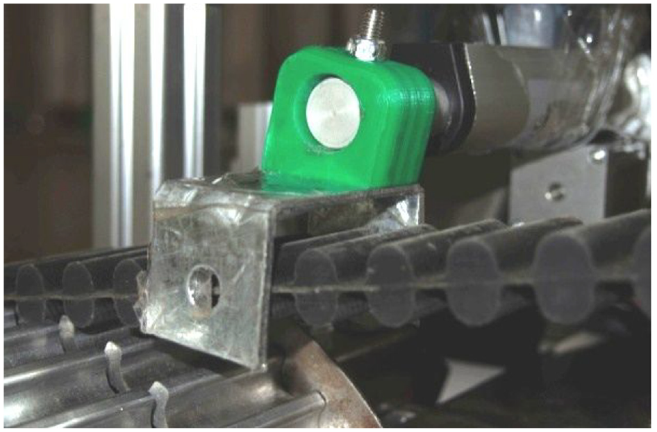
Real picture of the fork.

Wheel track transformation demonstration picture.

Shape picture of solid wheel.

Crawler shape picture of real vehicle.

Picture of solid wheel driving.

Picture of real vehicle crawler crossing mire.

Picture of real vehicle crawler obstacle crossing.

Real wheel track transformation picture.
Schedule of wheel track transformation.

From the above table, the time for wheel-to-track conversion is longer than that for track-to-wheel conversion, which is consistent with the description in the above analysis. The average time of both is slightly longer than the theoretical time due to the pause of the stepper electric cylinder when the control system receives multiple conversion instructions. However, its impact is small and both wheel-to-track and track-to-wheel conversion times have reached their design requirements. This indicates that the new type of coupled wheel/track off-road robot designed in this paper is feasible.
As depicted in Figure 17, the shifting fork is fabricated from C-shaped steel and connected to the stepping push rod via a 3D-printed plastic block. Additionally, it is wrapped with adhesive tape on the exterior to minimize the friction coefficient, thereby reducing resistance and wear during wheel-track transitions. Figure 18 presents snapshots of the wheel-track transformation process. When the shifting fork moves to engage the drive wheel/hanging wheel with the track, it slightly reduces the rotational speed of the drive wheel due to an increase in equivalent inertia. However, this effect is minimal during ground locomotion as the change in equivalent inertia of the locomotion mechanism is relatively insignificant compared to the inertia of the entire vehicle.
Figure 19 depicts the wheeled configuration of the robot, where the tracks are hung on the hanging wheels and do not contact the ground. And the propulsion is provided by the first pair of load-bearing wheels. In contrast, Figure 20 illustrates the tracked configuration of the robot, which is like conventional tracked robots, where the propulsion is generated by the drive wheel wrapping around the tracks.
Figure 21 demonstrates the wheeled locomotion state of the robot. As the power is transmitted via chains, the tight side of the chain between the drive wheel and the first pair of load-bearing wheels is located on the upper side during forward motion. Additionally, since the propulsion is solely provided by the first pair of load-bearing wheels, the robot is limited to operating on hard surfaces. In contrast, Figure 22 shows the tracked locomotion state of the robot, capable of off-road traversal. In this state, the tight side of the chain between the drive wheel and the first pair of load-bearing wheels is located on the lower side during forward motion. This is due to the slightly larger transmission ratio between the drive sprocket and the driven sprocket compared to that between the drive wheel and the load-bearing wheels.
As depicted in Figure 23, the actual vehicle is capable of traversing obstacles of a certain height. This is attributed to the large diameter of the drive wheel and the wide span of the load-bearing wheels, which together provide sufficient thrust to enable the drive wheel to overcome obstacles when in contact. Figure 24 illustrates the process of transforming the robot from tracked to wheeled configuration. During this transition, the shifting fork moves inward, causing the tracks to gradually detach from the load-bearing wheels, starting from the front and ending at the rear, while being hoisted by the tensioning wheel to separate from the ground. During this process, the first pair of load-bearing wheels initiates contact with the ground, facilitating the switch in traction force sources.
Conclusion
Firstly, the mechanical structure, control system, and wheel-track conversion process of the coupled wheel/track robot were designed and analyzed, and finite element analysis was performed on the heavily loaded structural components. Due to its structural characteristics of separating tracks, this coupled wheel/track off-road robot avoids the appearance of complex tire structures and solves the problems of complex traditional coupled wheel/track structures and poor reliability. Moreover, when stuck due to improper operation in wheeled mode (when the driving wheel is suspended), it can still escape by switching to tracked mode. Therefore, this structure is more convenient for mass production and practical use. In addition, since this coupled wheel/track mechanism relies on the automatic assembly and disassembly of tracks for wheel-track conversion and does not depend on the expansion and contraction of tracks, it can use metal tracks that are difficult to use by other coupled wheel/track mechanisms. This allows this type of special robot to operate normally in fire scenes and strong corrosion areas.
Secondly, the kinematic models of the robot in wheeled and tracked states were established and analyzed, and the calculation formula and experimental method of important parameter γ in the kinematic matrix were given. Through prototype measurement on specific roads, the relationship curves between γ ratio and turning radius in wheeled and tracked modes were obtained respectively, providing theoretical support for subsequent algorithm control.
In addition, by analyzing conditions such as the center of gravity on the ability of robots to cross vertical obstacles, it was concluded that this robot can cross a vertical obstacle of 310.47 mm. In addition, after prototype measurement, it can cross a step of about 300 mm, which is basically consistent with the calculated analysis results.
The calculation of the fork results during wheel-track change shows that it takes about 5 s for the robot to complete the transformation of wheel-track walking state at a vehicle speed of 3 m/s. The physical prototype was brought into a hard road surface for vehicle inspection. The results show that this type of robot can complete the transformation from wheeled to tracked mode in about 6.6 s; it can complete the transformation from tracked to wheeled mode in about 5.2 s, which is basically consistent with the calculated results. In addition, experiments have shown that this special robot has strong structural reliability and proved its obstacle-crossing ability.
Footnotes
Handling Editor: Sharmili Pandian
Declaration of conflicting interests
The author(s) declared no potential conflicts of interest with respect to the research, authorship, and/or publication of this article.
Funding
The author(s) disclosed receipt of the following financial support for the research, authorship, and/or publication of this article: Science Innovation Training Key Project for College Students in Jiangsu Province of China (Grant number 202211276018Z).