
Abstract
In view of the current situation of gradual degradation of grassland, this paper designs a water jet grassland root cutting machine based on root cutting improvement technology. The machine achieves the purpose of restoring grassland by the impact of high-pressure fluid on soil. In order to improve the working efficiency, an adaptive position adjustment device (following is referred to as APA device) is designed, which can ensure the adaptability of the fluidic sprinkler to the ground. In this regard, the overall structure and working principle of the water jet grassland root cutting machine are first analyzed. Furthermore, the dynamic model of the APA device is established based on the Lagrange equation, and the motion process of the device is simulated by MATLAB/SimMechanics. The results show that the APA device has good working efficiency in the smooth ground, and there is a significant vibration response in the protuberant ground. In order to reduce the vibration interference, the structure of the APA device is optimized based on the simulation results. The optimized simulation results show that the vibration response generated during the operation of the APA device is reduced, the vibration interference is reduced, and the optimization effect is significant.
Introduction
Grassland is an important natural resource and plays an indispensable role in the development of ecosystems. However, under the combined influence of natural disasters and human factors, grassland degradation has shown a trend of gradual deterioration. Data show that 49% of the grasslands in the world have different degrees of degradation, and have a serious negative impact on ecosystem function.1–3 Based on this, the restoration and reconstruction of degraded grassland has become a key ecological issue. At present, in the field of degraded grassland improvement, the commonly used restoration methods are mainly natural restoration and human-assisted improvement. Among them, the natural recovery methods include fence grazing prohibition and rotational grazing. Mekuria et al. monitored the soil properties within 1–7 years after the enclosure of public pastures. The results showed that the prohibition of mowing contributed to the increase of easily degradable substances in the soil. 4 Abagandura et al. identified the effects of different grazing densities on soil carbon content in grassland during an 8 year meadow rotational grazing study. 5 According to the relevant research results, this method has a certain recovery effect on the grassland while controlling the grazing time and reducing the grazing intensity.6,7 However, due to the long cycle of this method and the unstable recovery effect on the grassland,8,9 the practical application frequency is not high. The artificial-assisted improvement method of grassland mainly relies on artificial active operating machinery to promote the growth and reproduction of grassland vegetation. The types include fertilization,10,11 subsoiling,12,13 drilling,14,15 root cutting,16,17 and other forms. Among them, root cutting improvement is considered to be one of the most effective measures for grassland restoration and improvement. At present, it mainly relies on hanging cutter for root cutting. There are some shortcomings in the process of operation, such as large resistance to soil entry and unstable root cutting depth.
In order to further curb the trend of grassland degradation and improve the efficiency of grassland restoration, this paper aiming at the shortcomings of the hanging cutter root cutting operation, and considering the current situation of drought and water shortage in degraded grassland soil, combined with the existing research foundation, 18 the design and improvement of the structure of the water jet grassland root cutting machine are carried out. This method mainly relies on the booster equipment to empower the water flow, and then through the fluidic sprinkler to carry out high-speed impact on the ground to complete the root cutting operation. In order to ensure that the fluidic sprinkler can adapt to the terrain while maintaining the characteristics of moving forward, a ground adaptive position adjustment device (following is referred to as APA device) is designed to ensure the impact operation efficiency of the fluidic sprinkler. Based on this, this paper first analyzes the overall structure and working principle of the water jet grassland root cutting machine. Taking the APA device as the object, the dynamic analysis model of the device is established, and the motion characteristics of the device are determined. The motion process of the device in different ground environments is simulated by MATLAB/SimMechanics, and the vibration response of the device is analyzed. Finally, the overall structure of the APA device is optimized and its effect is tested.
Overall structure design
The water jet grassland root cutting machine is a new type of root cutting method designed based on the current grassland root cutting improvement technology. This method requires a booster device to supercharge the water flow in order to complete the high-speed and high-pressure impact root cutting operation. Firstly, the overall structure and working principle of the root cutting machine are analyzed.
Overall structure
The three-dimensional model of the water jet grassland root cutting machine is drawn by SolidWorks, and the overall structure and related equipment are shown in Figure 1. The front of the whole machine is connected with the tractor through the Three-point hitch to realize the traction process. The fluid in the water tank realizes the process of pressurization and empowerment by means of the cooperation of the speed increasing box, hydraulic pump, regulating valve, and flow divider. The frame is designed as a double-layer structure to ensure the reliability of all equipment after fixed installation. A total of 12 sets of APA devices are installed in parallel hinges at the rear of the machine, which is convenient for adapting to terrain changes while moving forward. The relevant design parameters of the root cutting machine are shown in Table 1.
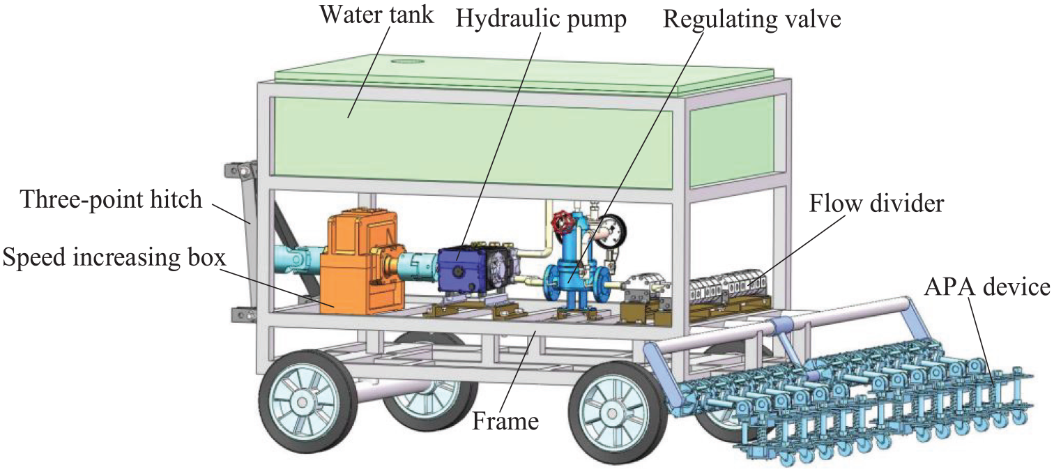
Overall structure of water jet grassland root cutting machine.
Related design parameters.

Working principle
The water jet grassland root cutting machine mainly relies on the impact of high-pressure fluid on the soil to achieve the effect of root cutting improvement, and its working principle is shown in Figure 2. The tractor outputs power to the speed increasing box while providing traction force. The speed increase box drives the hydraulic pump to run after the speed is increased, and at the same time, the fluid in the water tank is inhaled into the pump to complete the process of pressurization and empowerment. The pressurized fluid flows through the flow diverter under the control of the regulating valve, and finally is distributed to the fluidic sprinkler to complete the impact root cutting operation on the soil.

Working principle of the whole machine.
Structural design of key device
The APA device is the key device to improve the operation efficiency and recovery effect of the water jet grassland root cutting machine. This study mainly analyzes the structure, principle, motion, and simulation test of the device. Firstly, the overall design structure and working principle of the device are analyzed in detail.
Structural design
As a booster device in the restoration process of degraded grassland, the APA device can effectively improve the restoration effect and operation efficiency of grassland. The device has the structural advantage of adjusting its instantaneous shape with the change of grassland terrain, and the overall structure is shown in Figure 3. Among them, the fluidic sprinkler is the part that directly impacts and cuts the root of the grassland. The diameter of the flow area in the water outlet is small, and the flow consumption can be effectively saved with the cooperation of the pressurization equipment. The adjustment function of the device depends on the profiling principle of the ground, and the profiling process is mainly realized by the cooperation between the rotating rod, the support rod, and the bearing. The follow-up process of the device is realized by the friction rolling between the follower wheel and the ground. In addition, the protective cover is used to reduce the interference of the ground environment on the operation of the fluidic sprinkler, and the restricted spring is used to reduce the vibration interference of the fluidic sprinkler. The support rod is fixed at the rear of the frame, and multiple sets of the APA devices can be installed side by side to carry out the impact root cutting operation, which can improve the operation efficiency and realize the separate adjustment effect of the device on the ground. The limit sleeve is used to control the installation spacing of the adjacent APA device.

The structure of APA device.
Adjustment principle
The designed APA device is mainly installed behind the frame of the water jet grassland root cutting machine, and the impact root cutting operation is carried out while following the progress. Usually, multiple sets of APA devices can be installed side by side to improve the operation efficiency. According to the actual operation requirements of grassland, the length of the limit sleeve can be changed to control the spacing between adjacent APA devices, which has the characteristics of adjustable working spacing. In addition, when multiple sets of APA devices are arranged in parallel, the device can also meet the separate adjustment function in the parallel installation direction while ensuring the adjustment effect in the forward direction. The principle is shown in Figure 4.

The principle diagram of separate adjustment.
Dynamics analysis and simulation
In order to determine the applicability of the APA device to the ground in different degraded areas of the grassland, the dynamic analysis process of a single APA device was carried out to determine the motion law of the device during operation. The principle of separate adjustment of the device is verified by simulation, and the vibration response of the device is analyzed.
Dynamics analysis
According to the motion characteristics of each component of the APA device, the rear follower components is analyzed as a whole structure, and the centroid position is assumed to be S, then the device can be determined as a three-degree-of-freedom dynamic system. The coordinate system is established with the center of the support rod as the coordinate origin, so the mechanical geometric model of the device is shown in Figure 5. The structural mass of each part of the device is m1, m2, and m3, respectively. The overall structure moves forward under the action of the main power F1, and the displacement generated is x1. Under the influence of grassland terrain changes, the angular displacement generated by the rotating rod with a length of l is φ. The follower components present different position states under the action of their own gravity m3g, ground support force FN, ground friction Ff, and rotating rod tension Fp. In the actual motion process, when the APA device is in a balanced state, the motion characteristics of the device are analyzed as follows:

Force model of APA device.
In the dynamic analysis, the Lagrange equation is one of the widely used dynamic modeling methods.19,20 It provides a unified solution for the mechanical motion of the system. It mainly describes the various motion laws of the particle and the rigid body by establishing the Lagrange equation. The equation has the characteristics of constant form and is the most common dynamic equation in the complete ideal mechanical system. For the APA device designed in this paper, when using the Lagrange equation for dynamic analysis, first of all, for the non-conservative force field model of the system, the general form of the Lagrange equation is selected as 21 :

In the formula, L is the Laplace equation; T is the total kinetic energy of system; V is the total potential energy of system; q is the generalized coordinate of the system; F is the generalized force corresponding to the generalized coordinate; r denotes the position vector of a particle. Applying this formula to the structure of APA device, it can be determined that the generalized coordinate of the system is a function related to time t, which can be expressed as:
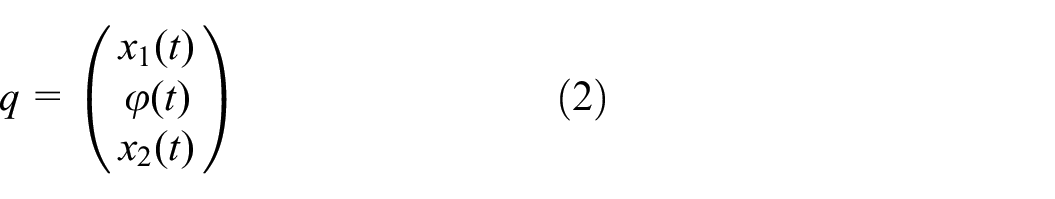
In the formula, x1(t) represents the displacement of the support rod position with time; φ(t) denotes the angular displacement of the rotating rod; x2(t) represents the overall displacement of the follower components. When the APA device is in a stable forward state during the forward process, the external forces on each component are:


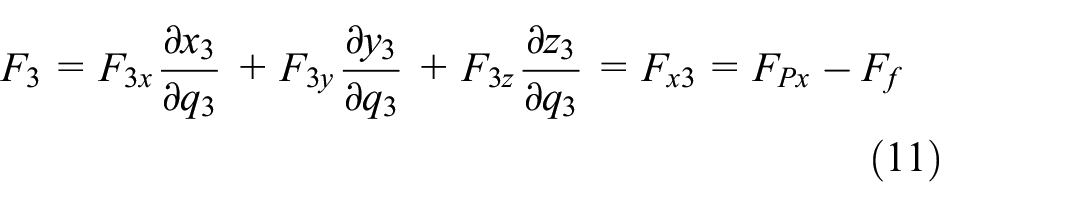
Thus, the generalized forces of the system are obtained as follows:


Accordingly, according to equation (1), the Lagrangian equation of the system can be further solved. When the APA device is moving forward, the position of the support rod is consistent with the forward position of the front-end machine. Under the influence of ground factors, the position of the rotating rod and the position of the rear follower components are in a real-time change state. In a certain period of time, the position coordinates of each component of the device can be expressed as follows:

In the formula, x1 is the forward displacement of the device at the support rod; l is the length of the rotating rod; φ is the angular displacement of the rotating rod; a is the displacement of the center of mass of the follower components from its side; b is the displacement of the center of mass of the follower components from its upper end. Thus, the total kinetic energy of the system during the motion of the APA can be expressed as:

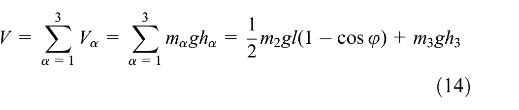
h α is the height change of each component of the device. From equations (13) and (14), the Laplace equation of the system can be further obtained:

According to this, after solving the Laplace equation (15) according to the equation (1), the system dynamics equation of the APA device is obtained as follows:

The second-order differential equations in the above formula can be used to describe the motion law of the APA device at any time. Since the forward traction force of the device remains unchanged when it is installed behind the machine, the forward speed of the machine will also affect the position of the APA device in addition to the interference of ground factors in actual operation.
Dynamic vibration response analysis
In order to determine the adaptability of APA device to the grassland ground environment, different types of grassland ground models were first established, and the ground roughness curve were generated by simulation. Further, based on the different ground models generated, the displacement variation trend of APA device is own vibration response during operation is simulated.
Establish ground model
In the process of the APA device being pulled forward, the vertical displacement will be generated under the excitation of the grassland ground factors. The variation range of the displacement is derived from the influence of the grassland ground roughness characteristics and the terrain environment changes. Among them, the ground roughness is determined by the road surface power spectrum density. According to the ISO 8608 document issued by the International Organization for Standardization, the road roughness is divided into eight levels according to the power spectrum density of the road surface,22,23 and the corresponding power spectrum is shown in Table 2. Here, the one-sided power spectral density function described can be expressed as 24 :

Classification standard of road roughness grade.

In the formula, Gd(n) represents the spatial one-sided power spectral density, m3; n is the spatial frequency, m−1; n0 is the spatial reference frequency, which is 0.1 m−1; w is the frequency index.
According to the classification standard of pavement grade, the grassland ground based on C-grade pavement is selected to simulate the vibration response displacement of the APA device. The simulation model is built by using the filtered white noise method of the MATLAB/Simulink module as shown in Figure 6. Taking the unilateral power spectrum as an example, the noise power is set to 0.5 W, and the random road surface model within 10 s is generated according to the traction speed of 1.2 m/s, as shown in Figure 7.

Ground roughness simulation model.

Road roughness distribution curve.
The Figure 7 shows that the vertical displacement of the grassland ground environment based on the C-grade road surface is between 0 and 60 mm. In order to determine the vibration response of the APA device in different ground environments, two ground models with different cross-section curve types shown in Figure 8 are selected for comparative study. Figure 8(a) shows the protuberant ground with vertical height h1 of 20, 40, and 60 mm, respectively. The ground model will be used to analyze the dynamic vibration response of the APA device. Figure 8(b) is a smooth ground with peak height h2 of 60, 80, and 100 mm respectively, which is mainly used for comparative analysis in vibration response.

Type of section curve of ground model: (a) protuberant ground curve and (b) smooth ground curve.
Physical modeling and simulation
SimMechanics is a visual physical modeling tool in MATLAB, which includes rigid body, coordinate system, hinge constraint, contact force, and other unit modules to model and simulate the mechanical system structure.25,26 When the SimMechanics model of the APA device is built, the structure of each component is drawn separately by SolidWorks software, and it is imported into MATLAB for parameter setting and position constraint of the unit model. The resulting SimMechanics block diagram model is shown in Figure 9.

Block diagram model of APA device.
In the simulation of the advance process of APA device, the cross-section curve model shown in Figure 8 is used as the ground model. The stiffness coefficient of the contact between the follower wheel and the ground is set to 1150 N/mm, the damping coefficient is 1.27 N/(mm/s), and the Transition Region Width is 0.1 mm. After applying the driving torque to the wheel, the traction process is simulated. In order to analyze and determine the vibration response displacement of the device, three kinds of ground peak height and three kinds of forward speed are set on the basis of two kinds of ground models for comparative study. The parameter settings are shown in Table 3.
Setting of simulation parameters.

Before the simulation test, in order to detect the vibration displacement between APA device and the ground during the advance process, the Transform Sensor module is used as the data analysis source for the simulation post-processing. According to the given parameters in Table 3, the simulation results are as follows:
Figure 10 is the displacement curve of the vibration response of the APA device in the protuberant ground environment at three forward speeds. It can be clearly seen from the figure that the peak height and time corresponding to the device under different velocity conditions are different, and the vibration response displacement generated when crossing the protuberant ground model is different. According to Figure 10(a), when the forward speed of the device is 1 m/s, the vibration response displacements generated by the protuberant ground with corresponding peaks of 20, 40, and 60 mm are 3.05, 5.53, and 7.52 mm, respectively. Therefore, the height change of the protuberant ground peak will affect the vibration response of the APA device, which is mainly manifested in the fact that the vibration response of the device gradually increases with the increase of the peak value. Combined with Figure 10(b) and (c), it can be seen that the device also presents this change rule at different speeds. Comparing the data curves of Figure 10(a) to (c), it can be seen that when the peak value of the protuberant ground is 60 mm, the vibration displacement of the device corresponding to the forward speed of 1, 1.5, and 2 m/s is 7.52, 8.09, and 9.02 mm respectively, and the vibration response displacement has an increasing trend. When the peak value is 20 and 40 mm, the vibration response displacement of the device does not change much. Therefore, the forward speed of the device has little effect on its vibration response.
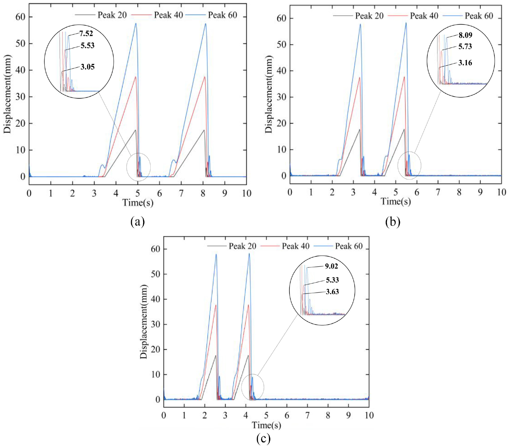
Protuberant ground simulation data curve: (a) V = 1 m/s, (b) V = 1.5 m/s, and (c) V = 2 m/s.
Figure 11 is the vibration response displacement curve of the APA device in a smooth ground environment at three forward speeds. Comparing the data curves in Figure 11(a) to (c), it can be seen that there is no significant vibration response displacement change when the APA device advances in a smooth ground environment with peak values of 60, 80, and 100 mm. When the speed is 2 m/s, it can be seen from Figure 11(c) that the ground environment with a peak value of 100 mm will have a small impact on the vibration response of the APA device.

Smooth ground simulation data curve: (a) V = 1 m/s, (b) V = 1.5 m/s, and (c) V = 2 m/s.
According to the above simulation results, it can be seen that the vibration response of the APA device is less significantly affected by the smooth ground environment, so it can ensure a certain operating efficiency. The vibration response of the device in the protuberant ground environment is more significant, which will affect its actual operation efficiency. It is necessary to optimize the structure of the device to improve efficiency.
Structural optimization of the APA device
Optimize structure
According to the vibration characteristics of the APA device, the overall structure is shown in Figure 12 after the optimization design. In order to reduce the vibration response displacement of the APA device in the protuberant ground environment, a tensile spring is added to generate an internal tension, thereby imposing a rotational torque constraint on the rotating rod. In addition, since the vibration response of the APA device directly affects the stability of the fluidic sprinkler, a damping spring is added to the follower wheel structure to reduce the vibration.
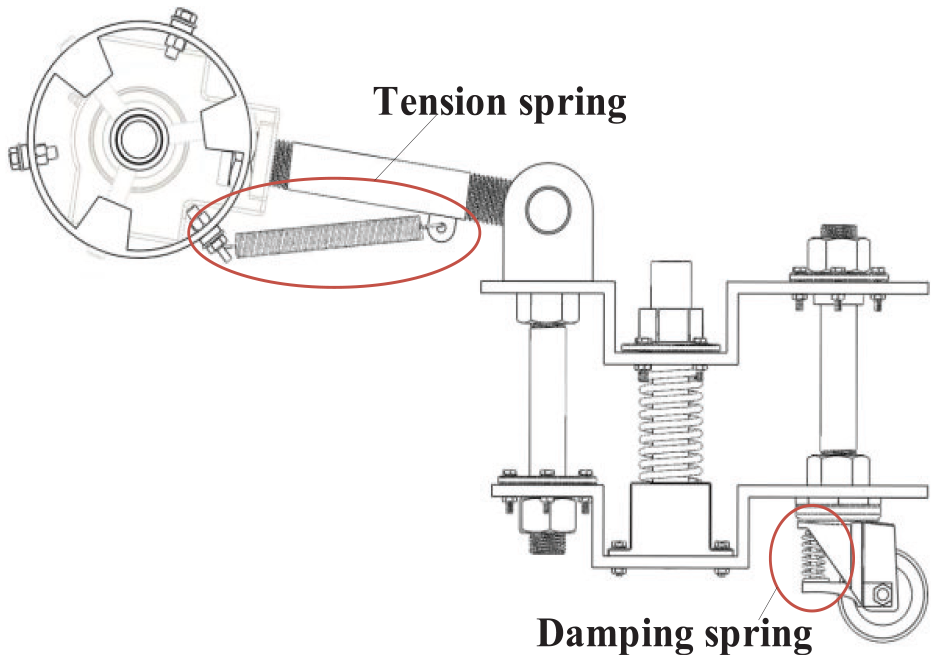
The optimized structure of APA device.
Mechanical analysis
Aiming at the optimized structure of the APA device, the force analysis is carried out to understand the internal vibration reduction principle. Firstly, the force analysis of the rotating rod constrained by the tensile spring is carried out, and the force model is shown in Figure 13. Among them, the length of the rotating rod is l, its own gravity is m2g, and the components of the joint force of the support rod to the rotating rod in the x and y directions are f1x, f1y. The components of the joint force of the rotating rod in the x and y directions are f2x, f2y. T1 and T2 are the feedback torque of the ground environment and the follower components to the rotating rod; f3 is the tensile spring force, and its component force in the direction of the rotating rod and the vertical rotating rod is f31 and f32. Based on this, the motion equation can be obtained after the force analysis of the rotating rod:


Analysis model of force on rotating rod.
In the formula, AS1x and AS1y are the accelerations of the centroid S1 along the x and y directions, respectively. I is the moment of inertia of the rotating rod; α is the angular acceleration of the joint. It can be seen from the above formula that the spring force f3 is the main variable force in the force of the rotating rod, which can make the follower components be constrained to the ground direction in the protuberant ground environment, thus to achieve the purpose of vibration reduction.
For the follower components, in order to reduce the vibration of the fluidic sprinkler, after adding the damping spring at the follower wheel, the follower components is a two-stage vibration reduction system, and its dynamic model is shown in Figure 14. Among them, M1 is the mass of the fluidic sprinkler, M2 is the mass of the lower fixed plate, k1 and c1 are the elastic coefficient and damping coefficient of the constraint spring, k2 and c2 are the elastic coefficient and damping coefficient of the damping spring, x1 and x2 are the vertical displacement of the fluidic sprinkler and the lower fixed plate respectively. Based on this, the dynamic equation of the two-stage vibration reduction system of the fluidic sprinkler is established as follows:


Two-stage vibration reduction model of fluidic sprinkler.
The two-stage vibration reduction principle used in the above-mentioned dynamic equation is also widely used in the stability analysis of vehicles.27,28 This paper, this formula is used to describe the vertical displacement change during the operation of the fluidic sprinkler of the APA device, thus to analyze the vibration response change trend of the APA device after structural optimization.
Simulation analysis
When simulating and analyzing the optimized structure of the APA device, Spring and Damper Force is added to the SimMechanics block diagram model in Figure 9 to simulate the constraint elasticity of the spring. According to the three-dimensional model structure of the device, in the module parameters of the tension spring, the natural length is set to 0.11 m, the spring stiffness is 10 N/m, and the damping coefficient is 0.2 N/(m/s). In the module parameters of the damping spring, the natural length is set to 0.034 m, the spring stiffness is 10 N/m, and the damping coefficient is 0.3 N/(m/s). The optimization results obtained by simulating the optimized structure are as follows:
Figure 15 shows the vibration response results of the optimized structure of the APA device when working in the protuberant ground environment. The figure shows that compared with the structure before optimization, the vibration response displacement gap of the APA device at three different operating speeds is reduced, and the vibration response is significantly reduced. When the device works at a speed of 2 m/s on the peak ground of 60 mm, the vibration response displacement is 3.85 mm, which is about 5 mm lower than that before optimization. From the simulation results, it can be seen that after optimizing the structure of the APA device, the vibration response displacement relative to the ground is reduced, which can further improve the working efficiency of the device.

Optimize the vibration response displacement of the structure: (a) V = 1 m/s, (b) V = 1.5 m/s, and (c) V = 2 m/s.
Figures 16 and 17 are the parameter variation curves of the tension spring and the damping spring after the structural optimization of the APA device. It can be seen from Figure 16 that with the increase of the peak height of the protuberant ground, the elasticity and elongation of the tensile spring gradually increase. Taking the 60 mm protuberant ground peak as an example, Figure 16(a) shows that due to the different time of the frame and the APA device crossing the protuberant ground, there is a positive and negative difference in the elastic direction of the tensile spring, and the overall variation range is −140.42 to 176.84 N. Figure 16(b) shows that the spring elongation corresponding to the elastic force varies from −16.99 to 15.21 mm on the basis of 110 mm. It can be seen from Figure 17 that the parameter variation frequency of the damping spring is high. Figure 17(a) shows that because the upper end of the damping spring is fixedly constrained, the elastic force is mainly distributed on the near-ground side (negative direction) during the operation. When the peak value of the ground protrusion is 60 mm, the positive force point of the elastic force is 14.39 N. Since the number of positive forces is small, it has little effect on the structure. Figure 17(b) shows that when the peak value of the ground protrusion is 60 mm, the elongation range of the damping spring on the basis of 34.5 mm is −0.98 to 2.08 mm, which is basically consistent with the vibration response displacement shown in Figure 15.

Parameter curve of tensile spring: (a) elastic force of tensile spring and (b) elongation of tensile spring.

Parameter curve of damping spring: (a) elastic force of damping spring and (b) elongation of damping spring.
According to the above simulation results, after optimizing the structure of the APA device, under the constraint of the corresponding spring, the vibration response of the device is weakened, the overall structure tends to be stable, and the optimization effect is obvious.
Conclusion
In view of the current situation of grassland degradation, this paper designs a water jet grassland root cutting machine based on the root cutting improvement technology. The machine improves the grassland environment by impacting the soil with high-pressure water flow. In order to further improve the working efficiency of the impact root cutting, an adaptive position adjustment device (APA device) is designed to make the fluidic sprinkler have the characteristics of real-time change with the ground. Based on this, this paper first analyzes the overall structure and working principle of the water jet grassland root cutting machine. After the dynamics analysis of APA device, the vibration response of APA device in different ground environment is simulated. Finally, the structure optimization and effect test of the device are completed. The main research methods and conclusions are as follows:
(1) The operation process of the APA device in different ground environments was simulated by MATLAB/SimMechanics. The results show that the device has good adaptability in the smooth ground environment, and there are different degrees of vibration response in the protuberant ground environment.
(2) Based on the vibration response results of the APA device in the protuberant ground environment, the optimization design and simulation test of the structure of the device were carried out. The results show that the vibration response of the optimized APA device in the protuberant ground environment is reduced, and the optimization effect is obvious.
Footnotes
Handling Editor: Aarthy Esakkiappan
Declaration of conflicting interests
The author(s) declared no potential conflicts of interest with respect to the research, authorship, and/or publication of this article.
Funding
The author(s) disclosed receipt of the following financial support for the research, authorship, and/or publication of this article: This study was supported by the Natural Science Foundation of Inner Mongolia Autonomous Region (Grant No. 2023LHMS05029), the Inner Mongolia Autonomous Region Science and Technology Major Project (Grant No. 2020ZD0002), key R & D projects in Shandong Province (Grant No. 2021JMR0302), scientific research project of Inner Mongolia University of Technology (Grant No. BS2021032 and ZZ202103).