
Abstract
In this paper, the model predictive current control (MPCC) is proposed to reduce the torque ripple of a switched reluctance motor by realizing precise current tracking. The Linear Quadratic Regulator (LQR) is employed to establish the cost functions of MPCC, which can select optimal control variables. Besides, the Kalman filter is employed to estimate the system state to reduce the influence of disturbance. In addition, the PI controller is replaced by automatic disturbance rejection control (ADRC) to further improve the robustness of the system. Finally, experimental results are shown to verify the effectiveness regarding distinguished tracking performance, dynamic response, and robustness of the proposed MPCC. It can be found that the improved MPCC proposed in this paper can achieve lower torque ripple, distinguished current tracking performance, and dynamic response performance.
Keywords
Introduction
As mature motor technologies, permanent magnet (PM) motors and induction motors (IMs) have been widely employed. However, the harsh operation environment in the engine and the high cost of the permanent materials decrease the attention on the PM motors.1,2 In addition, the IMs are usually criticized for their power factor lag and poor speed control performance. Hence, more and more attention has been paid to permanent materials free and wide speed range motors, such as switched reluctance motors (SRMs).3–7 Due to the high robustness and stability, low cost, simple structure, and wide speed range, the SRMs are becoming powerful candidates.8,9 A series of researches, including nonlinear modeling,10,11 position sensorless drive systems,12–17 and torque ripple reduction,18,19 have been significant topics. Among these researches, the torque ripple reduction is necessary to make up for the inherent drawbacks of the SRMs.
The optimization of the structure20–25 and advanced control strategies26–28 are two practical methods to decrease the torque ripple. In terms of control strategies, several advanced control schemes, including the sliding mode control,29–33 torque sharing function control,34–37 direct torque control,38–41 and model predictive control (MPC)42–44 are investigated. Among them, the MPC attracts more attention for its fixed switching frequency, fast response, and distinguished ability to handle constraints of system variables. Hence, the MPC will be researched to control the current in Section “Model of MPCC for SRM.” MPC has been widely used in modern times due to the rapid development of computer technology. The error of numerical integration can be ignored due to the development of computing tools with high performance. The relevant mathematical model used in model prediction has become a common method.45–47
In order to decrease the computation burden, two main groups of predictive control that are usually applied in drive applications, which are deadbeat predictive control,48,49 and finite control set-MPC (FCS-MPC).50–52 The deadbeat predictive control can obtain great dynamic and static tracking performances with less computational effort.53,54 However, this method is absolutely related to the accurate SRM model. The mismatch or change of the SRM parameters would make the actual values depart from the reference values. By comparison, the FCS-MPC has better robustness and stability. Except for these common MPC methods, some other MPC methods are incorporated into MPC for performance enhancements, such as pulse-width modulation control 55 and model-free MPC. 56 For instance, a model-free predictive control is proposed, which only utilizes the stator currents and the current differences. 57 However, the accuracy of MPC depends on the precise model. The variable of the parameters would cause the deviation of the control signals. This is the main challenge for MPC to be widely employed. In this paper, the Kalman filter is employed to improve the conventional MPC. This estimation method can estimate the flux and increase the robustness of the conventional MPC system.
The electric torque of SRM is related to the phase current. Hence, precise current regulation is a method to reduce torque ripple. The model predictive current control (MPCC) is proposed in this paper, which is used as a current-close control loop. Typically, the PI control is added to realize a speed-close loop, which is a common approach employed to improve the static tracking performance of the control system in many applications. However, the disturbance would have an obvious influence on the dynamic performance of PI control. Moreover, there is a conflict between the response time and the overshoot of the system inevitably. Hence, several advanced control methods can be applied to the improved control strategy to further improve the performance, such as fuzzy PI, 58 adaptive PI, 59 and ADRC. 60 The fuzzy PI and adaptive PI will improve the complexity of the system. 61 Hence, the automatic disturbance rejection control (ADRC) has been employed to improve the robustness of PI.62–64 In ADRC, the unknown disturbance can be estimated and compensated. In addition, ADRC does not rely on the precise model. This method can further improve the robustness and dynamic response performance of the system. Hence, the ADRC will be researched in Section “Modified MPCC with ADRC” to replace the typical PI control to realize a speed-close loop. The design of the speed controller does not conflict with the improved MPCC techniques.
The remainder of this paper is organized as follows. Section “Model of MPCC for SRM” presents the modeling process of MPCC for SRM. Section “Modified MPCC with ADRC” proposes a modified MPCC with ADRC. Finally, the performances of the proposed MPCC are verified by experiment results in Section “Experimental result,” followed by the conclusion in Section “Conclusion.”
Model of MPCC for SRM
Dynamic model of MPCC
To ensure phase independence and simple control, the asymmetric half-bridge circuit is employed for SRM drives; the topology circuit is shown in Figure 1. There are two chopping types for this topology structure, including hard-chopping and soft-chopping. Compared with the hard-chopping, the soft-chopping just turns off the low switch device without returnable current. It can decrease chopping frequency to reduce switch losses. Hence, the soft-chopping is employed in this paper.

The asymmetric half-bridge.
Moreover, the hysteresis current, the eddy current, and the mutual inductance between adjacent phases are neglected in the dynamic model to reduce the computational burden. With these assumptions, the dynamic model is expressed as

where ψ(t), i(t), V(t) are the phase flux, the phase current, and the phase voltage, respectively. R is the phase resistance. θ(t) is the rotor position, which can be measured by the hall position sensors. For soft-chopping type, the phase voltage can be expressed as

where Vdc is the bus voltage and d(t) is the conducting time of pulse-width-modulation (PWM) signals. In view of the nonlinear characteristics and inductance saturation of the SRM, the phase inductance is associated with the rotor position and the phase current. Hence, the phase current can be calculated as

However, digital devices operate under a discrete-time state. Hence, it is necessary to transfer the continuous-time model (1) to a discrete model. The Euler-Discrete function is employed to derive the discrete-time model as

where T s is the sample time. In addition, u k is the duty cycle of PWM signals, which is applied to control the switch device in the asymmetric half-bridge topology circuit. It is worth mentioning that b k is an unchanged parameter if Vdc and T s are ensured.
The inductance and resistance play important roles in the model of the SRM. The environment has few impacts on the resistance, which can be assumed as a constant to simplify the dynamic model of MPCC. Compared with the resistance, the inductance is easily affected. On the other hand, the inductance variations are caused by changes in the magnetic circuit, which are regular and related to the rotor positions and the current. Therefore, the phase inductance of the SRM can be estimated by using the Fourier series. Since the harmonic component is much smaller than the fundamental component, the Fourier series can be simplified as

where N r is the number of rotor poles. Lmax, Lmin are aligned and unaligned phase inductance of the motor under the same phase current i k , respectively.
Matrix form of MPCC
The MPC is widely employed in tracking control applications for its efficient tracking capabilities. Typically, it can find the optimal control variables by calculating cost functions to reach the optimal objectives. Generally, the cost functions include a quadratic tracking error function and a quadratic control variable function. It is assumed that the constraints are ignored to improve the computational speed of the MPC controller. In addition, the predictive horizon and control horizon are denoted as P and M (M < P), respectively. ψ k represents the flux linkage model at the kth step. Moreover, the duty cycle u k is the output of the MPC controller and is applied to control the switch device. Several control variables in the control horizon are expressed as U k (matrix size is M × 1). Similarly, coefficients in (4) in the predictive horizon are expressed as the matrix form A k (P × 1), B k (P × M), and C k (P × 1), respectively. Then, the Euler-discrete function is employed to establish the matrix form of MPCC in the predictive horizon, which can be expressed as

where

Since the inductance is related to the rotor position and current, it is difficult for this matrix form to predict the rotor position precisely and decrease the computational burden. Hence, the matrix form needs to be further simplified. It is supposed that the inductance is fixed in a prediction period, which means the inductance in the predictive horizon is the same as the inductance at the kth step, as shown as

Then, the matrix A k and B k can be changed as

Furthermore, the Linear Quadratic Regulator (LQR) is employed to establish the cost function, which is expressed as

where q
i
and r
i
are weight factors, and (

where Q and R are the error weight matrix and control weight matrix, respectively. I* is the reference current matrix. Combining with (6), the quadratic cost function can be derived as

By setting

Finally, the control variable of the kth step can be calculated by uk|k = cTU k , where cT is expressed as cT = [1, 0, …, 0]T.
Important parameters
There are several important parameters which have influences on the tracking stability and control performance of MPCC.
The sample time T s must be selected based on the Shannon sampling theory and the model parameters of the SRM. The small sample time will increase the calculation frequency and decrease the real-time performance of the controller. On the contrary, the robustness and stability will be affected under large sample time. The sample frequency of LQR is set as 10 kHz.
The selection of the predictive horizon P and control horizon M is also important. If M = P = 1, the predictive issue is simplified to choose the control signal uk|k to make the predictive current ik+1|k = i ref , which is denoted as deadbeat control. However, this control type will generate the ripple and is sensitive to the interference. Hence, the predictive horizon P should be increased to strengthen the robustness of the system. In addition, the larger M would improve the control performance. However, the upper limit should be considered to reduce the computational burden. Meanwhile, the relationship M < P should be satisfied.
The error weight matrix Q is selected by model parameters, which is set as identity matrix
Flux estimation
The variations would cause the deviation of the control signals of MPCC. Hence, the Kalman filter is employed to estimate the flux and improve the robustness and accuracy of the controller. The linear system state equation is used to establish the Kalman filter.
Concretely, the prior and posterior error estimations of the flux are expressed as (“−” represents the prior estimation and “^” represents the posterior estimation)

The covariance functions of the error estimate can be expressed as

where K k is denoted as Kalman gain value and can be calculated by the equation.

Since ψ k may be affected by the disturbance, the Kalman filter is employed to maintain an estimation of the mean of ψ k . Based on the previous assumptions and established model, the flux can be estimated as

The estimation flux would be transferred to the MPCC controller to predict the current. The control structure of MPCC is shown in Figure 2.

The control structure of MPCC.
Modified MPCC with ADRC
The system with PI control is easy to be disturbed by the external environment. Therefore, the ADRC has been applied to improve the robustness of the system. Figure 3 shows the typical structure of ADRC, which includes the tracking differentiator (TD), nonlinear state error (NLSEF), and extended state observer (ESO). ADRC classifies the unknown disturbance as the total disturbance. Then, the total disturbance is estimated by ESO and compensated by the appropriate NLSEF. In addition, the TD is employed to establish a stationary transient, which impels outputs approaching reference value smoothly.

The nth ADRC control block.
The modified MPCC with ADRC is proposed to improve the performance of MPCC in this section. The control structure of improved MPCC is shown in Figure 4. The out-loop is the speed loop which is ADRC and the inner-loop is current control which is MPCC. The inputs of ADRC are given reference speed ω ref and feedback speed ω k , and the output is reference torque T ref . Moreover, the inputs of MPCC are reference current i ref , position signals θ k , and feedback current i k .
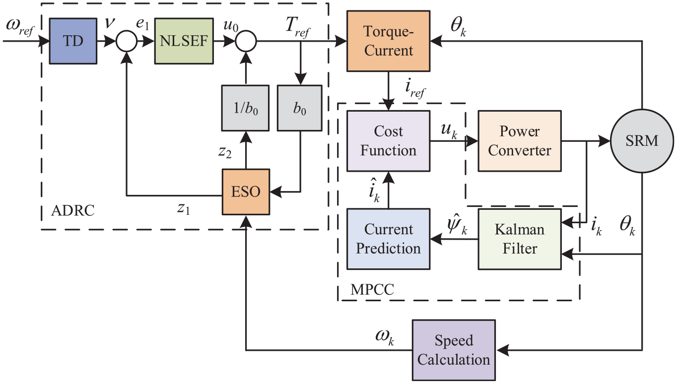
The modified MPCC with ADRC.
Design of TD
The difference between given signals and reference signals is usually used are control signals, which contain disturbance unavoidably. In addition, the response time conflicts overshoot of the system inevitably. Hence, as a signal processor, TD is employed to solve these problems by integration, which arranges the transition process of signals.
Before designing TD, the torque equation of SRM can be established. The total torque T e is expressed as

where J, D, and T L are inertia, damping coefficient, and load torque, respectively. The speed is selected as the control object of ADRC, and the dynamic system is yielded as

where y is the output speed ω k . Then, the total disturbance, including inner and external disturbance, is defined as

The dynamic system can be rewritten as

where b0 is equal to 1/J and u out is T ref . After establishing the dynamic system (21), the TD can be expressed as

where r, α0, and δ0 are parameters need be regulated.
Design of ESO
The ESO is a type of estimator. It is employed to track speed signal x1 and total disturbance x2 in this paper, respectively. The tracking parameters are z1 and z2 corresponding to x1 and x2. The ESO is expressed as

where α1, β2, δ1, α2, β2, and δ2 are parameters need be regulated.
Design of NLSEF
According to the outputs from TD and ESO, the ADRC compensates for the total disturbance via establishing a nonlinear relationship between the difference of these outputs. Then, the output of ADRC (reference torque T ref ) can be expressed as

where α3, β3, and δ3 are parameters.
Experimental result
In order to verify the accuracy of the mentioned analysis regarding the proposed MPCC, the prototype and the experiment setup are shown in Figures 5 to 7, respectively. As shown in Figures 5 and 6, there is a permanent magnet ring between the two stators, and the torque pole is bonded through the aluminum blocks. The torque pole is wrapped with the torque windings. The bias flux provided by the permanent magnet ring forms a closed path only through the suspension pole and does not pass through the torque pole. Therefore, suspension control is independent of torque control, and the bearingless SRM can be used as an ordinary SRM to test and control. Thus, the proposed control scheme is suitable for other SRMs. The specifications of the motor are shown in Table 1.
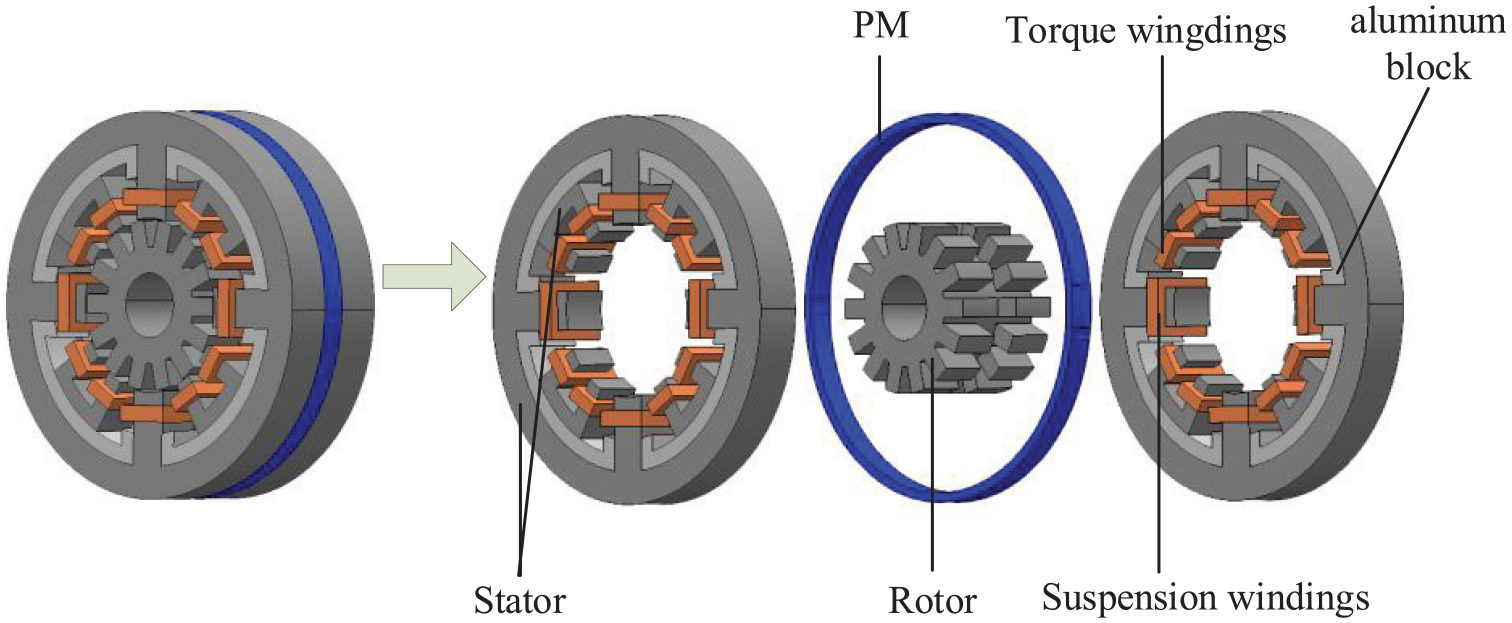
The structure.

The prototype.

The experiment setup.
Specifications of the motor.

As shown in Figure 7, the prototype, magnetic powder brake PB-A-1.2, and torque and speed sensor JN338 are interconnected via two couplings. The position signal detected by the Hall sensor ATS675LSE is fed into the controller, which in turn generates the switching signal based on the compiled control system. The measuring range and measuring error of torque sensor JN338 are 20 N m and 0.2%, and those of speed sensor JN338 are 18000 r/min and 0.5%. As for magnetic powder brake PB-A-1.2, the measuring range and measuring error are 12 N m and 1%. The speed and torque data measured by the sensor JN338 are exported and drawn by the drawing software. The bandwidth of torque transducer JN338 used in the experiment is 500 Hz–50 kHz. First of all, the required peripherals are configured in the compilation environment, and then the control strategy is compiled accordingly. Finally, the control chip is downloaded to carry out the experiment. Because no table lookup method is used in the proposed control scheme, no two-dimensional table data is stored in the storage unit, so the memory required is not large. To validate the effectiveness of the proposed strategy, experimental comparisons were conducted with MPCC using PI control (strategy 1) and MPCC using adaptive fuzzy PI control (strategy 2). For the selection of control parameters, we first use the dichotomy method for parameter debugging and narrow the range of parameters. Then, we used the optimization algorithm to find the value of the parameters. The difference between the stable speed and the given speed is set as the goal.
Figure 8 shows the experimental results of three control strategies including speed and torque performance at 0.4 N m under 2000 r/min. As presented, the speed of the three strategies can all realize the stable tracking of the reference speed. Furthermore, the dynamic response time of strategy 1, strategy 2, and the proposed MPCC are 0.26, 0.25, and 0.21 s, respectively. It indicates that the proposed MPCC has the best performance in dynamic response in the initial stage. As for torque, as shown, the torque values can be well controlled around 0.4 N m. Besides, the maximum and minimum torques of the proposed MPCC are 0.64 and 0.17 N m, while those of strategy 1 are 0.77 and 0.1 N m, and those of strategy 2 are 0.72 and 0.14 N m. The torque ripple ranges of strategy 1, strategy 2, and proposed strategy are 0.67, 0.58, and 0.47 N m, respectively. It means that the proposed MPCC system can reduce the torque ripple compared with strategies 1 and 2.

Speed and torque under 2000 r/min and 0.4 N m: (a) strategy 1, (b) strategy 2, and (c) proposed MPCC.
Figure 9 shows the experimental results of three control strategies including speed and torque performance at 0.4 N m under speed change (from 1600 to 2000 r/min). As presented, the speed of the three strategies can all realize the speed tracking when speed changes. The dynamic response time of strategy 1, strategy 2, and the proposed MPCC are 0.22, 0.2, and 0.18 s under 1600 r/min, respectively. It still indicates that the proposed MPCC has the superiority in the dynamic response. As for torque, the overshoot of torque occurs at 0.5 s when speed changes. Meanwhile, the torque ripple range does not change significantly when the speed changes from 1600 to 2000 r/min. Concretely, the torque ripple ranges of strategy 1, strategy 2, and proposed strategy are 0.65, 0.57, and 0.46 N m, respectively. It means that the proposed MPCC system behaves the best in the torque ripple reduction compared with strategies 1 and 2.

Speed and torque under speed change: (a) strategy 1, (b) strategy 2, and (c) proposed MPCC.
Figure 10 shows the experimental results of three control strategies including speed and torque performance under 2000 r/min and load torque changes from 0.4 to 0.7 N m. As shown, the speed of the three strategies can all track the reference speed well when load torque changes. The overshoot speed of the proposed MPCC is about 68 r/min when load torque changes, while those of strategy 1 and 2 are 186 and 177 r/min, respectively. It is obvious that the proposed MPCC is the best one among the three strategies as it has the lowest speed overshoots. As for torque, the maximum and minimum torques of the proposed MPCC are 1.1 and 0.4 N m when load torque changes to 0.7 N m, while those of strategy 1 are 1.9 and 0.26 N m, and those of strategy 2 are 1.16 and 0.3 N m. The torque ripple ranges of strategy 1, strategy 2, and proposed strategy are 1.64, 0.86, and 0.7 N m, respectively. Therefore, it reflects that the proposed MPCC provides much better control performance in terms of torque ripple suppression and anti-disturbance ability.

Speed and torque under load torque change: (a) strategy 1, (b) strategy 2, and (c) proposed MPCC.
Table 2 lists the experimental results of three strategies under different conditions for a more intuitive comparison. As shown, the proposed MPCC exhibits the best performance in terms of dynamic response, torque ripple reduction, and anti-disturbance ability.
Experimental results of three strategies.

Conclusion
This paper proposed a modified MPCC using a speed controller based on ADRC to suppress the torque ripple and influence caused by disturbance. In this paper, LQR was applied to select the optimal control variables according to the establishment of the cost functions. Then, the Kalman filter was introduced to enhance the anti-disturbance performance and robustness of the control system. Moreover, the LADRC was employed to design the speed controller to improve the dynamic response, tracking performance, and anti-disturbance performance. Meanwhile, the torque ripple can be further reduced. Compared with the PI control and fuzzy self-adaptive PI, the superiority of the proposed MPCC can be proved based on experimental validation under different working conditions.
Footnotes
Handling Editor: Xiaodong Sun
Author contributions
Conceptualization, L.H. and T.Z.; methodology, T.Z.; software, C.C.; validation, L.H., C.C., and T.Z.; formal analysis, L.H.; investigation, C.C.; writing – original draft preparation, L.H.; writing – review and editing, C.C. and T.Z. All authors have read and agreed to the published version of the manuscript.
Declaration of conflicting interests
The author(s) declared no potential conflicts of interest with respect to the research, authorship, and/or publication of this article.
Funding
The author(s) disclosed receipt of the following financial support for the research, authorship, and/or publication of this article: This research was funded by Jiangsu Province Higher Education Basic Science (Natural Science) Research Major Project, grant number 23KJA470001 and funded by Huaian City Key R&D Plan Projects, grant number HAG202302.
Data availability statement
Data are contained within the article.