
Abstract
For the problem of the rotor position estimation and control accuracy of permanent magnet synchronous motor (PMSM), this paper proposes a PMSM sensorless based on radial basis function (RBF) neural network optimized Automatic disturbance rejection control (RBF-ADRC) and strong tracking filter (STF) improved square root generalized fifth-order cubature Kalman filter (SGHCKF-STF). The Automatic disturbance rejection control (ADRC) has strong robustness, but there are many parameters and difficult to adjust. Now we use RBF neural network to adjust the parameters in ADRC online so as to improve the robustness and anti-disturbance ability. In order to improve the estimation accuracy of rotor position and speed, the orthogonal triangle (QR) decomposition and STF are introduced on the basis of the generalized fifth-order cubature Kalman filter (GHCKF) to design the SGHCKF-STF algorithm that not only ensure the non-positive nature of the covariance matrix but also improve the ability to cope with sudden changes in state during the filtering process. Experimental results show that the combination of RBF-ADRC and SGHCKF-STF improve the sensorless control effect of the PMSM to some extent.
Keywords
Introduction
Permanent magnet synchronous motor (PMSM) is widely utilized in the civil, aerospace and defense industries due to its simple structure, good dynamic performance and other advantages. To achieve high performance PMSM control, accurately measuring rotor position and speed is particularly crucial. In a traditional PMSM control system, the rotational speed is acquired by installing a mechanical sensor, but the mechanical sensor occupies a large space, which is not only vulnerable to environmental factors but also increases the cost and complexity of the motor. Sensorless control technology has become a research hotspot for PMSM control systems because of its strong environmental adaptability and low cost.
Common sensorless control of the PMSM technologies include the high frequency injection method, inverse potential integration method, state observer method and other methods. The high frequency injection method 1 needs to be based on the convex stage effect of the motor, which is more effective in the middle and low speed regions, but the estimation effect will become worse as the speed increases. The inverse potential integration method 2 estimates the rotor position from the stator voltage and current information monitored in real time at high-speed conditions, but a sufficiently large inverse potential cannot be obtained at low speeds. At present, state observation methods used to estimate rotor position and speed include the extended Kalman filter (EKF), 3 unscented Kalman filter (UKF) 4 and cubature Kalman filter (CKF). 5 The EKF transforms the nonlinear system into a linear system by expanding the nonlinear function into a Taylor series, omitting the higher order terms, and then using the Kalman filter principle, but the neglect of the higher order terms introduces truncation errors, and the estimation is poor and may diverge when the nonlinearity is enhanced. The UKF approximates the probability distribution of the nonlinear function by sampling near the estimation point, which overcomes the drawbacks caused by local linearization and can obtain higher estimation accuracy than EKF, but UKF does not work well when dealing with high-dimensional states. The CKF uses spherical integration and radial integration criteria to optimize the sampling method and weight proportion of sigma points in the UKF, improving the filter performance, but its estimation accuracy can only reach third order. To increase estimation precision even further, the generalized fifth order cubature Kalman filter (GHCKF) algorithm can be obtained by adopting the generalized fifth order cubature principle. 6 However, the UKF, CKF and GHCKF algorithms may cause the error covariance matrix to be nonpositive definite due to large rounding and initial value errors in the numerical calculation, which may lead to the instability or even failure of the filter.
In addition, it can also improve the PMSM control effect by optimizing the control algorithm. At present, commonly used control algorithms include the PI control, Sliding mode control (SMC) and Automatic disturbance rejection control (ADRC). The PI 7 control is simple, flexible and easy to adjust. However, when the controlled object becomes complex, the PI control cannot consider both good flexibility and toughness, and the ideal control result is tough to acquire. The SMC 8 can overcome system uncertainty, it has a quick reaction and strong robustness, however, as soon as the state trajectory touches the sliding mode surface, chattering will inevitably occur. The ADRC has been widely used because of its simple theory, excellent robustness, insufficient demand for a controlled object model and other advantages. Wu et al. 9 designed a new electro-hydraulic ostrich machine based on ADRC, which effectively improves the damping effect of the start stop transient structure, and has good stability and tracking performance under external interference. To improve the accuracy of mobile robot trajectory tracking when disturbed by external factors, Wang et al. 10 designed a trajectory tracking control method based on ADRC. To reconcile the conflict between observer response speed and system anti-interference brought by fixed bandwidth in ADRC, Wang et al. 11 designed a control system of the ADRC optimized by backpropagation (BP) neural network, the simulation and experiment demonstrate the significant robustness and adaptability of the ADRC optimized by BP neural network. Because a radial basis function (RBF) neural network can approximate any nonlinear function to avoid local minima and has great approximation, learning and analytical capabilities, Li et al. 12 designed a method to obtain the values in ADRC from the transfer function operations generated by RBF neural network training, so that the b-value of ADRC parameters can be adjusted in real time. Therefore, though ADRC performance is better, there are more parameters to be set, so the adaptive tuning and optimization of parameters in ADRC becomes important.13–15
In summary, for improving the performance of rotor position estimation and control accuracy of the PMSM, this paper proposes a sensorless control of PMSM based on RBF neural network optimized Active disturbance rejection control (RBF-ADRC) and strong tracking filter improved square root generalized fifth-order cubature Kalman filter (SGHCKF-STF). First, the PMSM discrete model is established, and the RBF-ADRC is used in the position loop of the PMSM control, the RBF neural network can adaptively adjust the values of three parameters in the extended state observer (ESO) of ADRC according to the PMSM operating state, thus improving the accuracy of the total disturbance estimation and the adaptive ability of ADRC. Second, the SGHCKF-STF algorithm is proposed which not only solves the problem of non-positive covariance matrix that may occur during the filtering process but also enhances the tracking ability of the system to cope with sudden states and improves the estimation accuracy of the filtering algorithm and the robustness of the system. Finally, the experimental analysis showed that compared to the CKF and GHCKF, the SGHCKF-STF algorithm has higher estimation accuracy for the rotor position and speed of the PMSM, and the RBF-ADRC has better control performance than the SMC and ADRC.
PMSM mathematical model
The object of study is a surface mounted PMSM, and the following assumptions are made: there is not oversaturation in the motor magnetic circuit, the motor current is a three-phase sinusoidal wave and the current is symmetrically distributed, the effects of hysteresis and eddy current losses are neglected and the core saturation effect is neglected. Therefore, the PMSM mathematical model in the stationary coordinate system can be expressed as follows:16,17
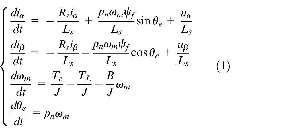
where iα and iβ are the stator winding’s current components, uα and uβ are the stator winding’s voltage components, Rs and Ls are resistor and inductor, respectively, ψf is flux linkage, ωm is the mechanical rotor angular velocity, pn is the polar logarithm, Te is the electromagnetic torque, TL is the load torque, B is the damping coefficient, J is the moment of inertia and θe is the rotor position angle.
Converting equation (1) into a state space expression:
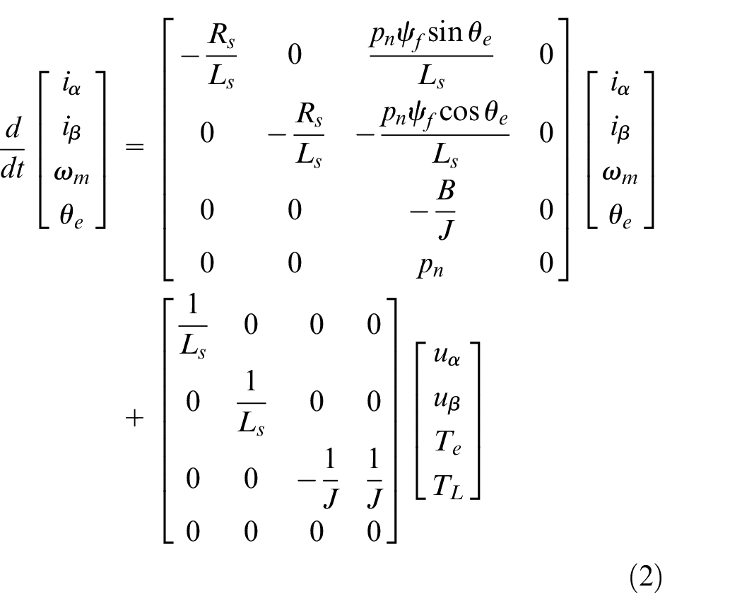
According to the forward Euler method, the PMSM mathematical model can be discretized as follows:
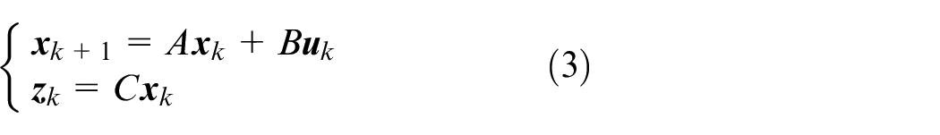
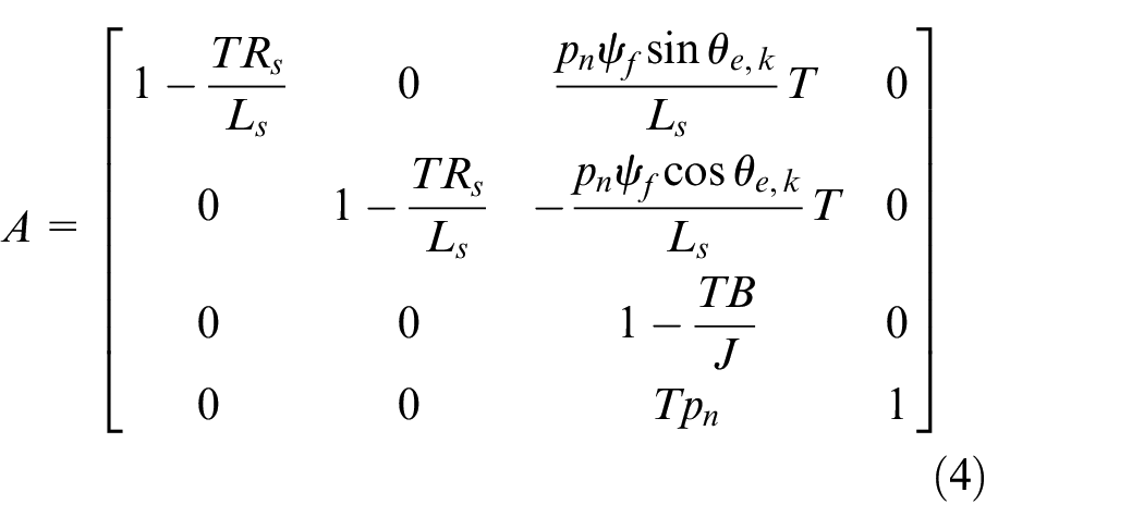
Assume the sampling time is T, the system matrix is:
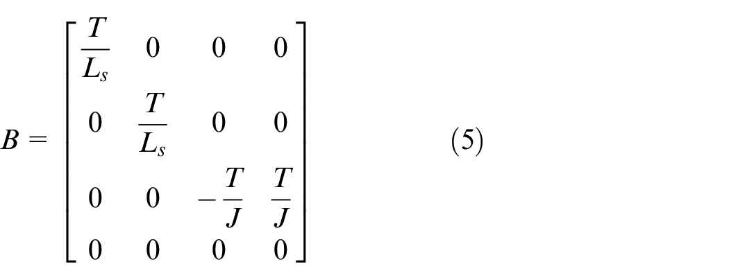
The input matrix is:
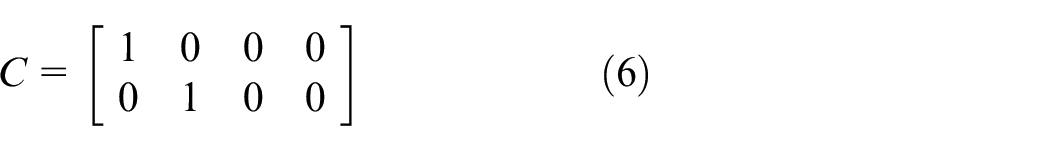
The output matrix is:
where
Sensorless control of PMSM
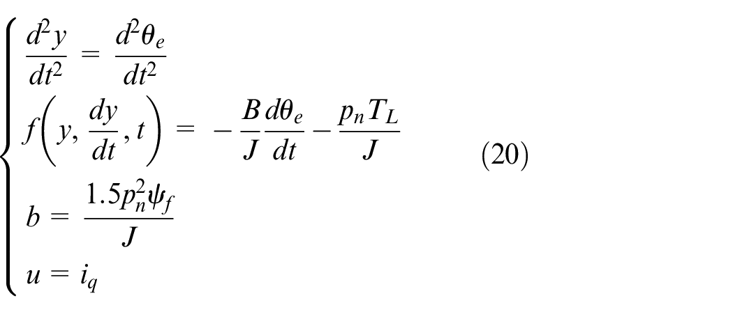
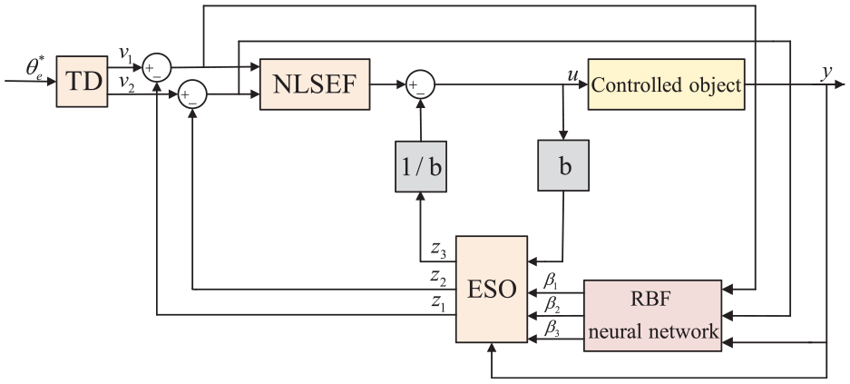
The RBF-ADRC designed in this paper is an online adaptive adjustment of the three parameters of ESO in the ADRC by RBF neural network to improve the control accuracy of PMSM. For the rotor position and speed information required in the control, the SGHCKF-STF algorithm is used to estimate the information according to the PMSM discrete model, and the PMSM control system is shown in Figure 1.
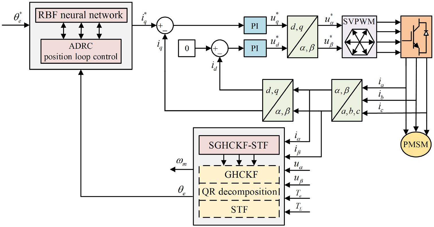
Sensorless control system of PMSM based on RBF-ADRC and SGHCKF-STF.
Design of position loop for ADRC
ADRC can be thought of as a combination of a tracking differentiator (TD), an extended state observer (ESO) and a nonlinear control rate (NLSEF).18–20 The TD is able to track the reference signal very quickly and give a differentiation of the reference signal, the ESO is used for perturbation observation and the NLSEF can adjust the error signal to nonlinear PID control. For the following system:
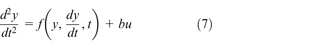
Changing the form of equation (7) to the state equation form by making x1 = y and x2 = dy1/dt as follows:
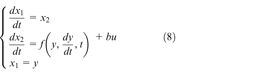
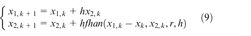
The TD as follows:
where
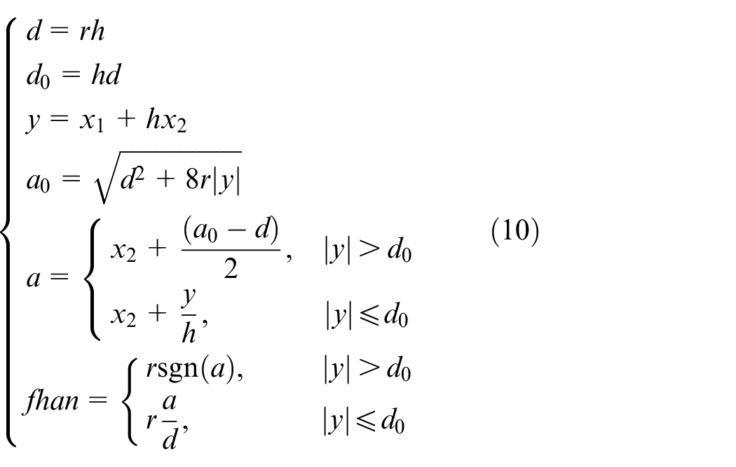
where h is the integration step, r is the velocity factor, fhan (·) is the synthesis function, xk is the input signal, x1,k is the tracking signal of the input signal and x2,k is the derivative of the input signal.
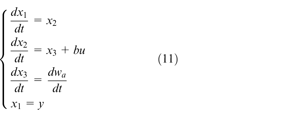
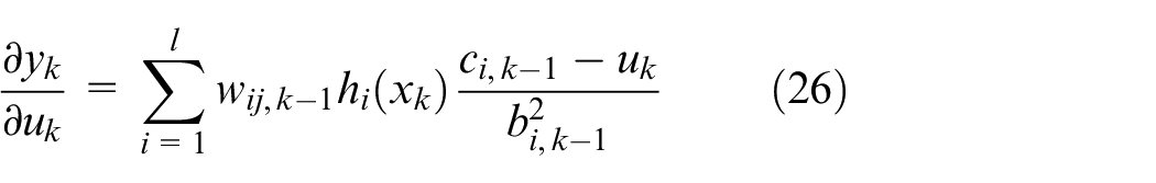
The ESO can observe the generated perturbations based on the input and output signals, and the total perturbation is expanded into new state variable wa, so that the original system becomes:
The ESO as follows:
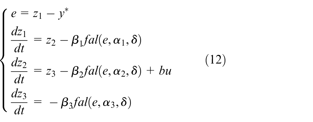
The fal (·) is a function that determines the degree of nonlinearity of the controller and satisfies as follows:
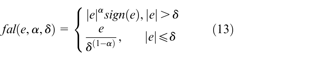
where z1 and z2 are variables describing the current state of the observer, z3 is the overall disturbance observation of the system, δ is the filter coefficient, β1, β2, and β3 are gain coefficients and α1, α2, and α3 are nonlinear coefficients.
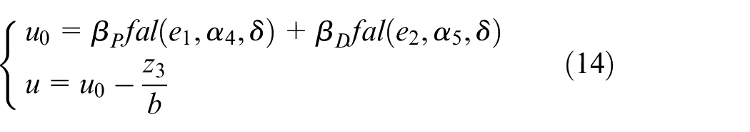
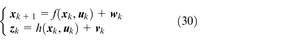
The NLSEF can rectify the error signal into a nonlinear combination similar to PID, and the following form of NLSEF expression is used in this paper as follows:
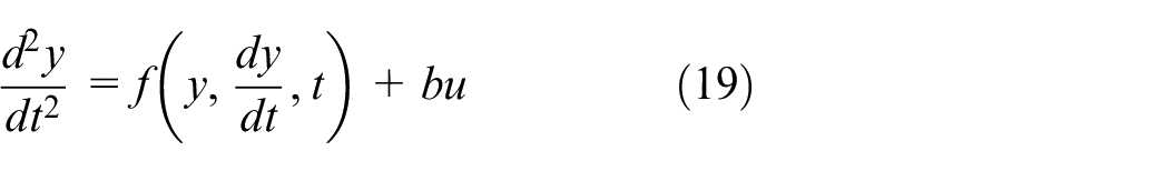
The proposed ADRC transforms the PMSM into a second order system as follows:
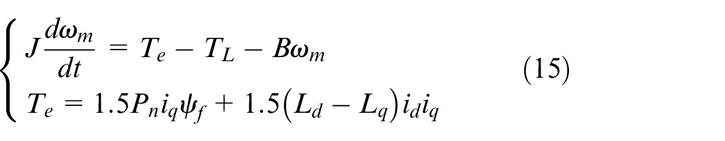
From the above formula, we can acquire as follows:
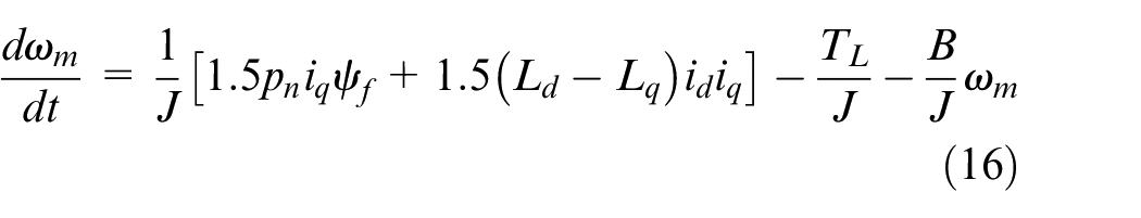
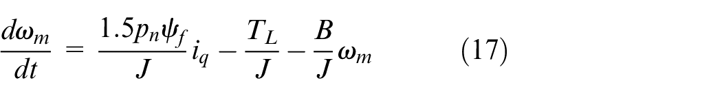
Using the control method of id = 0, the following results are acquired as follows:
Substituting
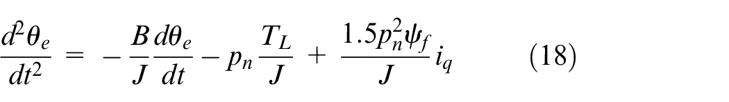
The mechanical equation of motion for PMSM can be reduced as follows:
where
According to the above inference, the ADRC designed is shown in Figure 2.
The structure of ADRC.
Design for RBF-ADRC
The three parameters β1, β2, and β3 in ESO directly affect the state estimation values z1, z2, and z3, where the estimation accuracy of z3 directly affects the accuracy of disturbance compensation, and the direct adjustment of these three parameters based on experience is time-consuming and does not fully utilize the benefits of ADRC. When these three parameters are fixed, the ADRC can have good control performance for systems with small changes in the controlled object, but when the controlled object changes a lot and the system is running fast, the control effect of ADRC will become poor. Therefore, this paper improves the robustness of ADRC by adaptively adjusting the β1, β2, and β3 through RBF neural network so that the system can change the values of these three parameters according to the changes and perturbations of the controlled object.
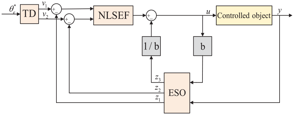
The three layers of RBF neural network are the input layer, hidden layer and output layer.21–23 The input layer is the signal source node, the hidden layer can convert the low-dimensional space vector into a high dimensional space vector to solve the problem of linear indistinguishability in low dimensional space and the output layer can output the information outputted from the implied layer after linear weighting. The structure of RBF neural network is shown in Figure 3.
The structure of RBF neural network.
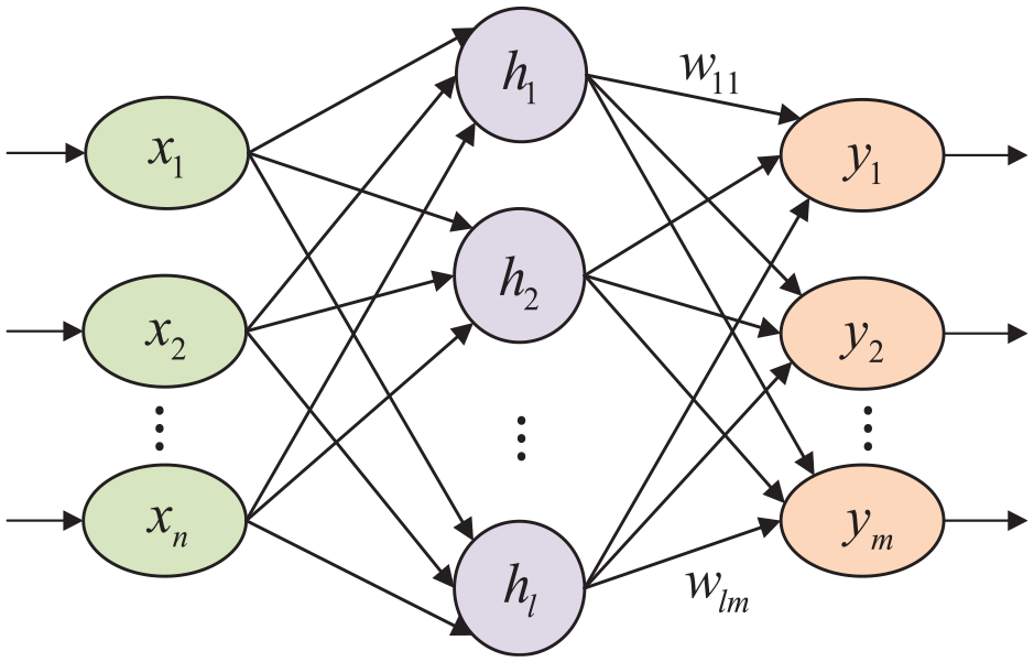
In Figure 3, n, l, and m are the numbers of input layers, hidden layers and output layers, respectively, the hidden layers to output layers connection weight value is w = [w11, w12, ···, wlm] T . The Gaussian function with good performance was chosen for the activation function as follows:
where ci is the central parameter of a hidden layers, and bi is the base width length.
The output layer output is:
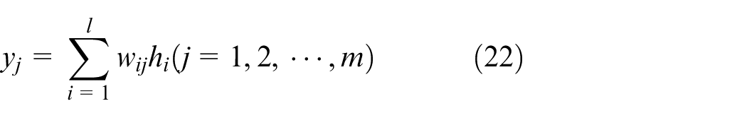
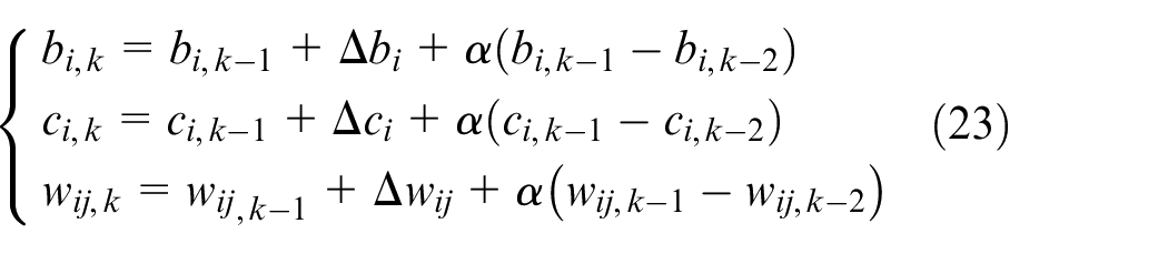
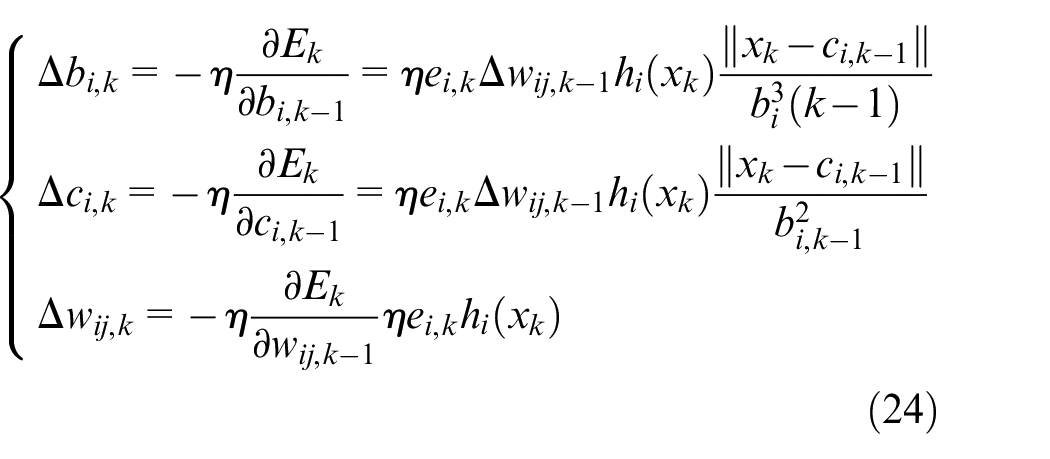
The ci, bi, and w training adopts a gradient descent method, the iterative formula as follows:
where
where η is the rate of learning, and α is the momentum factor.
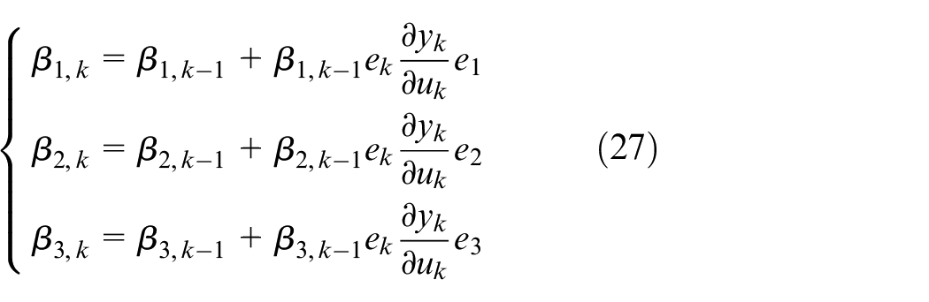
According to the system input and output error, the incremental coefficients of the three important parameters β1, β2, and β3 of ESO are:
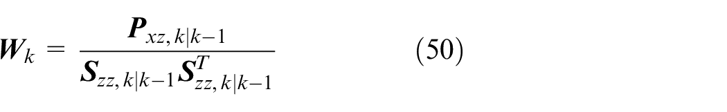
The Jacobian information of the system is:
The β1, β2, and β3 integration formula of the ESO as follows:
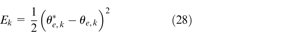
The performance index is:
The structure of RBF-ADRC is shown in Figure 4.
The structure of RBF-ADRC.
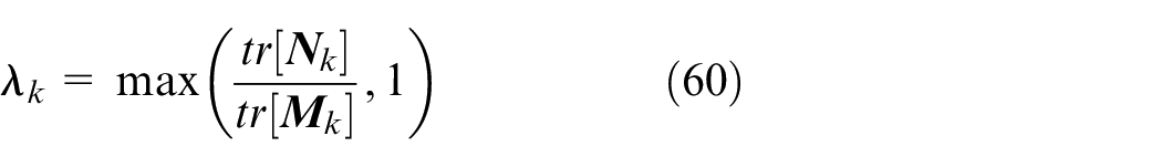
SGHCKF-STF algorithm
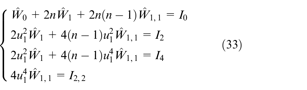
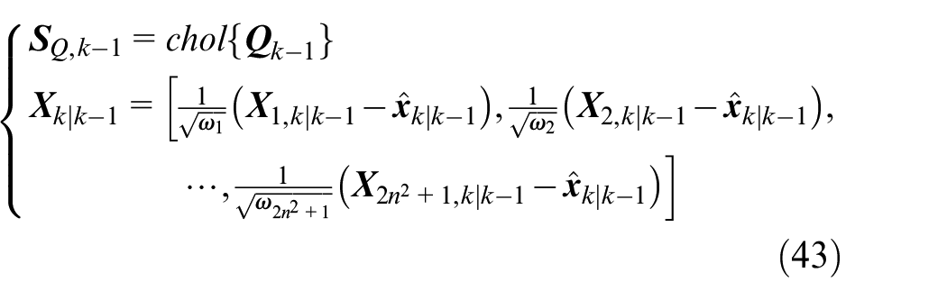
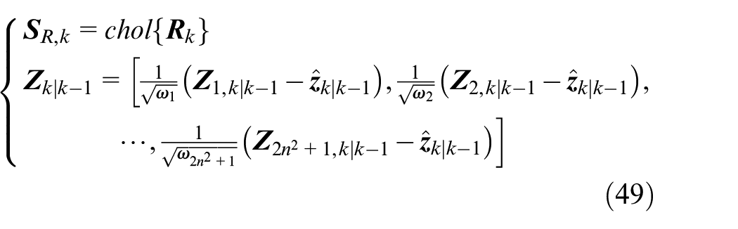
For the designed SGHCKF-STF algorithm, first, the GHCKF algorithm can be derived by combining the Bayesian estimation principle with the generalized fifth-order cubature principle. 24 Second, for further improve the stability of the algorithm, the orthogonal triangle (QR) decomposition is introduced on the basis of the GHCKF algorithm, which leads to the derivation of the SGHCKF algorithm. Finally, in order to enhance the tracking ability of the system to cope with sudden state changes, the STF is added to the SGHCKF algorithm, and the SGHCKF-STF algorithm is designed. For the discrete PMSM system, we can get from the equation (3) as follows:
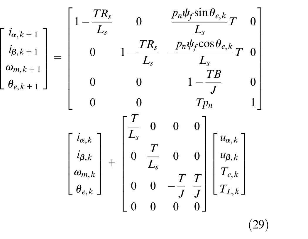
Consider PMSM discrete model with additive noise, we can transform equation (29) into the following form:
where
The formula for the generalized fifth-order cubature integral is:
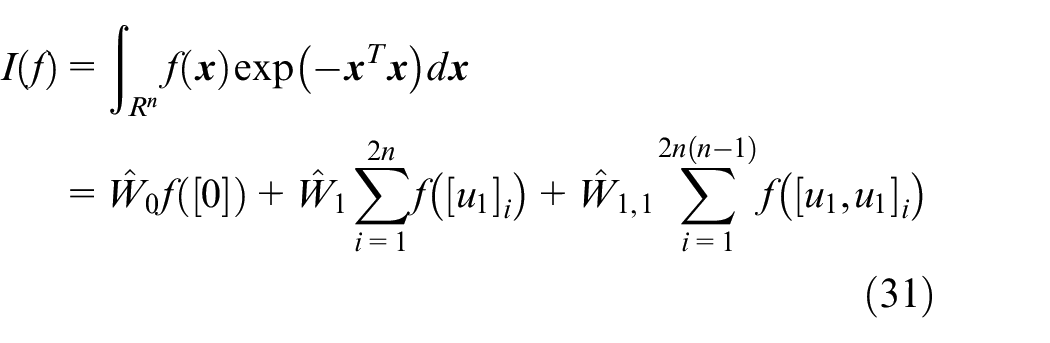
where
where Ŵ0, Ŵ1, and Ŵ1,1 are the weight values of the corresponding [0], [u1] i , and [u1, u1] i trajectories, respectively.
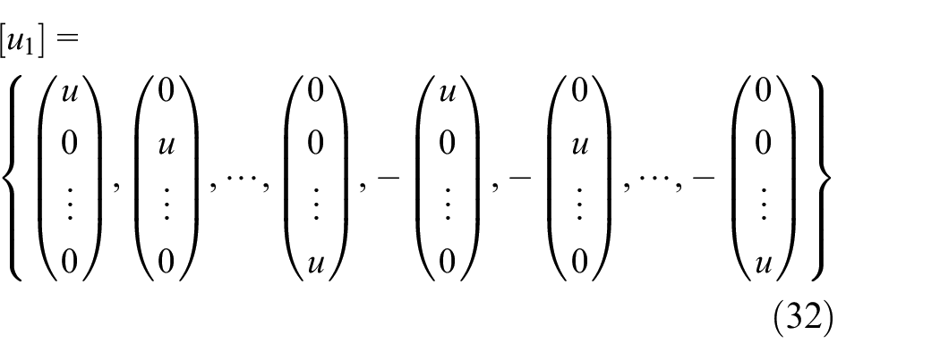
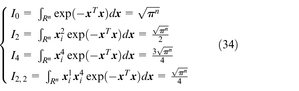
Use equation (31) to calculate the integral of
where
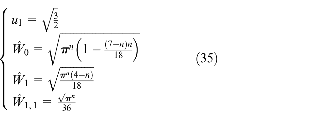
The unique solution can be found as follows:
The cubature integral of generalized fifth order is transformed into a standard Gaussian distribution as follows:
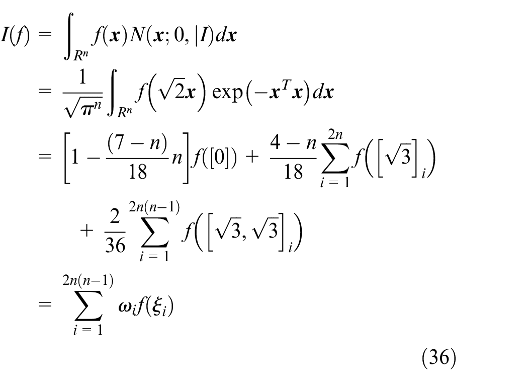
where the set of cubature point ξi and the weight ωi are:
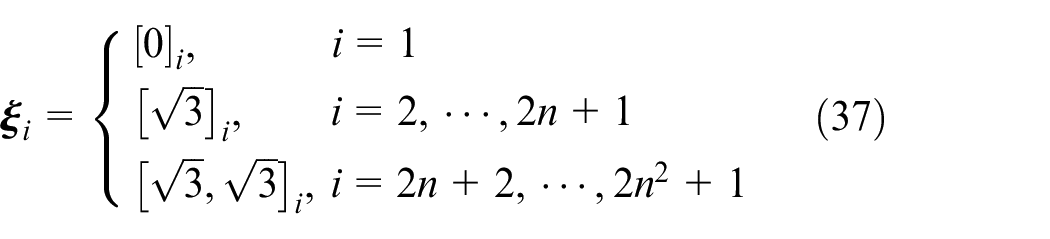
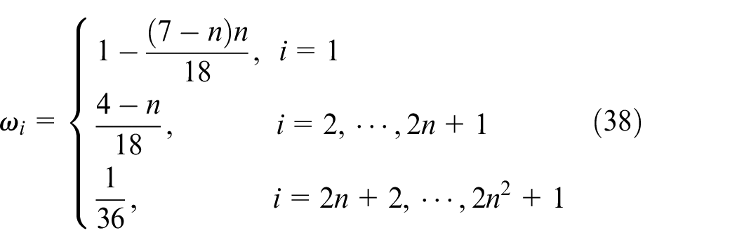
where n is the number of states.
The SGHCKF-STF algorithm flow is as follows:
a. Set the initial value
The initial value of state is
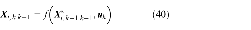
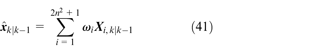
b. Time update
The propagation of the cubature points as follows:

The cubature points by propagation of the state equation as follows:
The predicted state value as follows:
The predicted square root of the error covariance matrix as follows:

where
c. Measurement update
The propagation of the cubature points according to the prediction as follows:

The cubature points by propagation of the measurement equation as follows:
The predicted measurement value as follows:
The correlation covariance matrix as follows:

The square root of the measurement error covariance matrix as follows:

where
d. State estimation
The Kalman gain as follows:
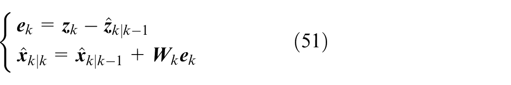
The measurement error value and estimated value of state as follows:
The square root of the error covariance matrix as follows:

e. Strong tracking filter (STF)
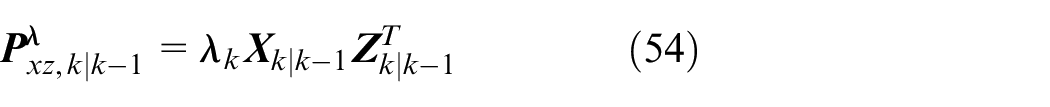
The PMSM is easily disturbed when operating under complex working conditions, which will lead to sudden changes in the system state and uncertainty of the system model. In order to further reduce the possibility of non-orthogonal residual sequences in the filtered output due to sudden changes in system state or uncertainties in the system model, the strong tracking filter (STF) 25 is introduced on the basis of the proposed a SGHCKF to force the residual sequence to remain orthogonal, to extract the effective information in the residual sequence to the greatest extent, and enhance the filtering algorithm’s robustness and accuracy. The STF generally adjusts the Kalman gain online and by the introduction of a fading factor λ k into the state to achieve the effect of quickly tracking the target state, so that:
The STF by introducing λ k to realize online adjustment of the Kalman gain. The recursive formula is:
The residual sequence is:
where ρ is the forgetting factor.
The fading factor λ k calculation formula as follows:

where
The SGHCKF-STF algorithm process is shown in Figure 5.
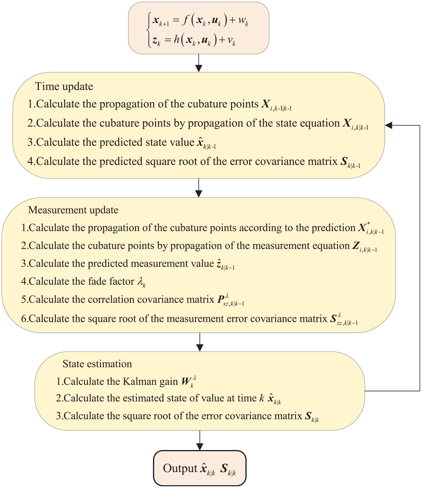
The SGHCKF-STF algorithm flowchart.
Experimental analysis
To confirm the actual control impact of the PMSM sensorless control based on RBF-ADRC and SGHCKF-STF algorithm, a motor experiment platform is established based on an upper computer, drive control box and PMSM as shown in Figure 6. First, the PMSM model based on the SMC, ADRC, and RBF-ADRC is opened in MATLAB/Simulink, and the CKF, GHCKF, and SGHCKF-STF algorithms compiled with the S-function to estimate states. Then, C code that can be run on the DSP is compiled via CCS 6.2, and the code is input to the drive control box. Finally, by commissioning the motor test bench equipment, data acquisition of the PMSM is performed and the corresponding experimental curves are drawn.
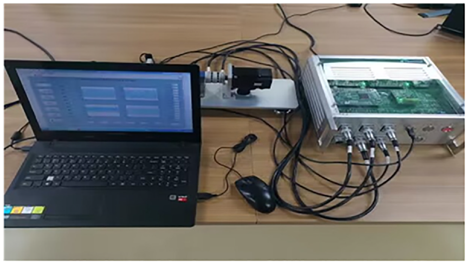
Motor test platform.
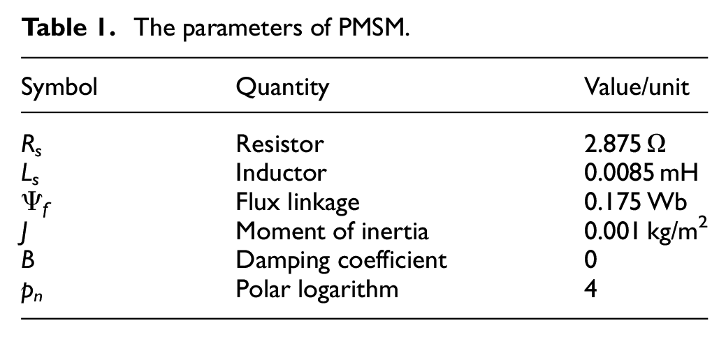
The following experiments are designed in this paper: (i) The CKF, GHCKF, and SGHCKF-STF algorithms are used to estimate the PMSM states under the sudden load and sudden change in speed, and the estimation error is calculated to compare the estimation accuracy of the three algorithms on the speed and rotor position under two conditions. This is done to verify the estimation effect of the SGHCKF-STF algorithm. (ii) By combining the SMC, ADRC, and RBF-ADRC strategies with the SGHCKF-STF algorithm, it is possible to assess the auto disturbance rejection and robustness of sensorless control under the sudden load and sudden change in speed, proving the effectiveness of the RBF-ADRC control method. During the experiment, the parameters of PMSM are shown in Table 1, and the experimental results are shown in Figures 7–12.
The parameters of PMSM.
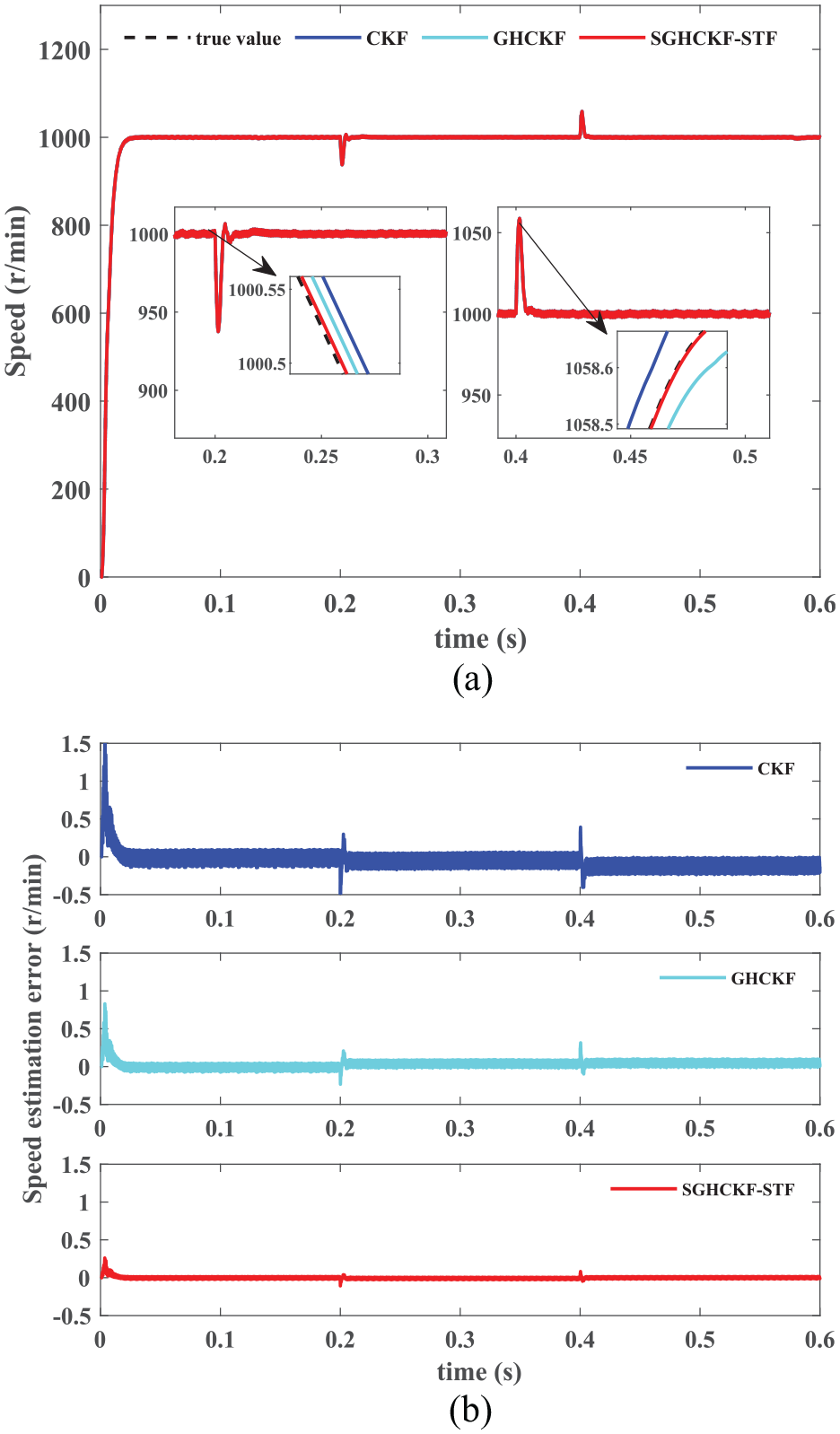
Speed estimation comparison curve under the sudden load: (a) speed estimation and (b) estimation error.
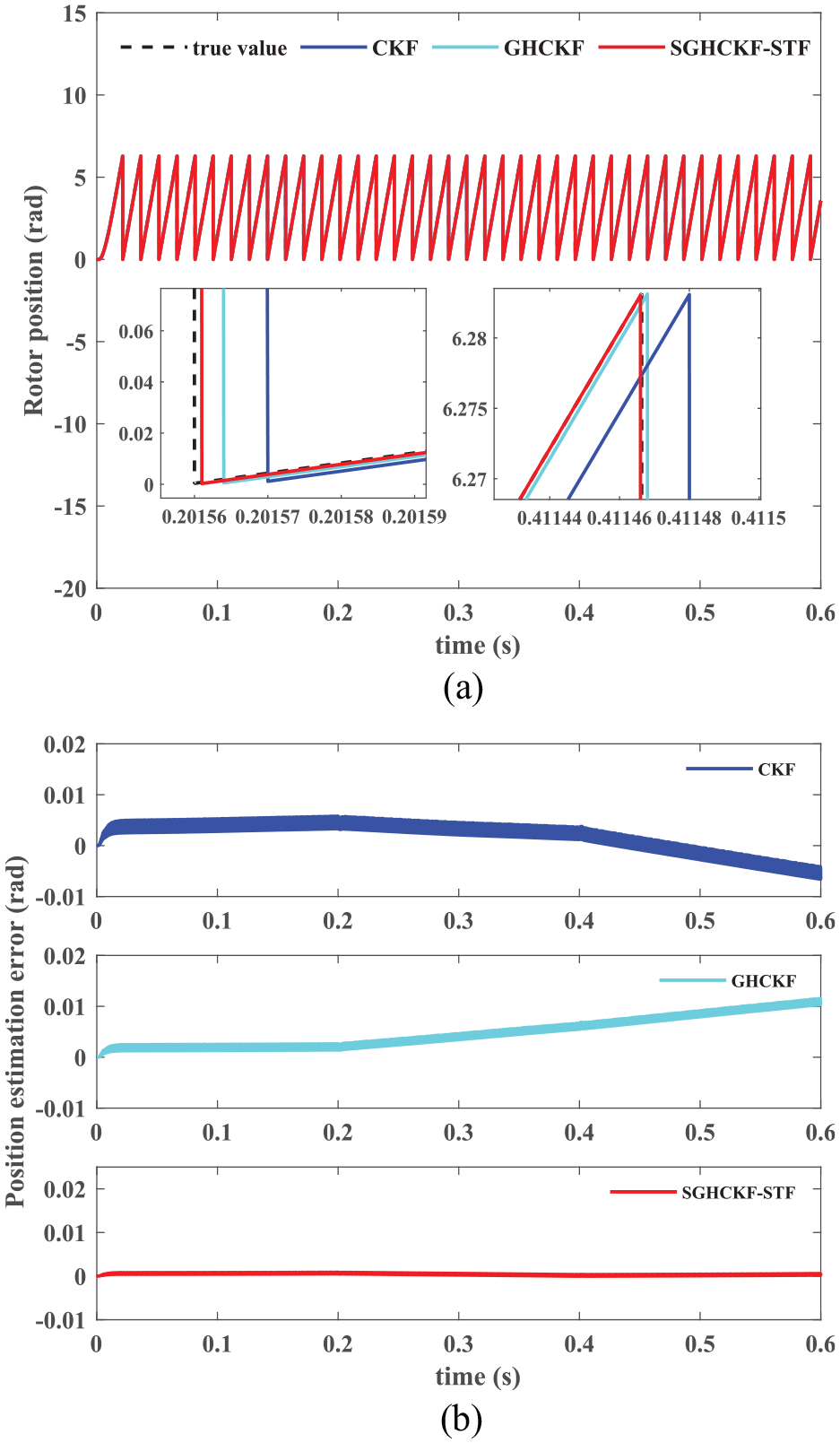
Rotor position estimation comparison curve under the sudden load: (a) rotor position estimation and (b) estimation error.
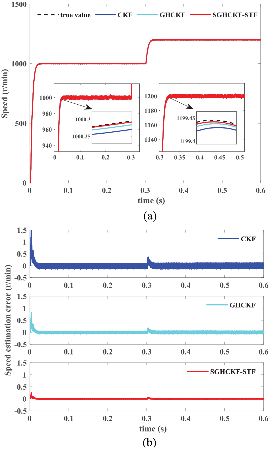
Speed estimation comparison curve under a sudden change in speed: (a) speed estimation and (b) estimation error.
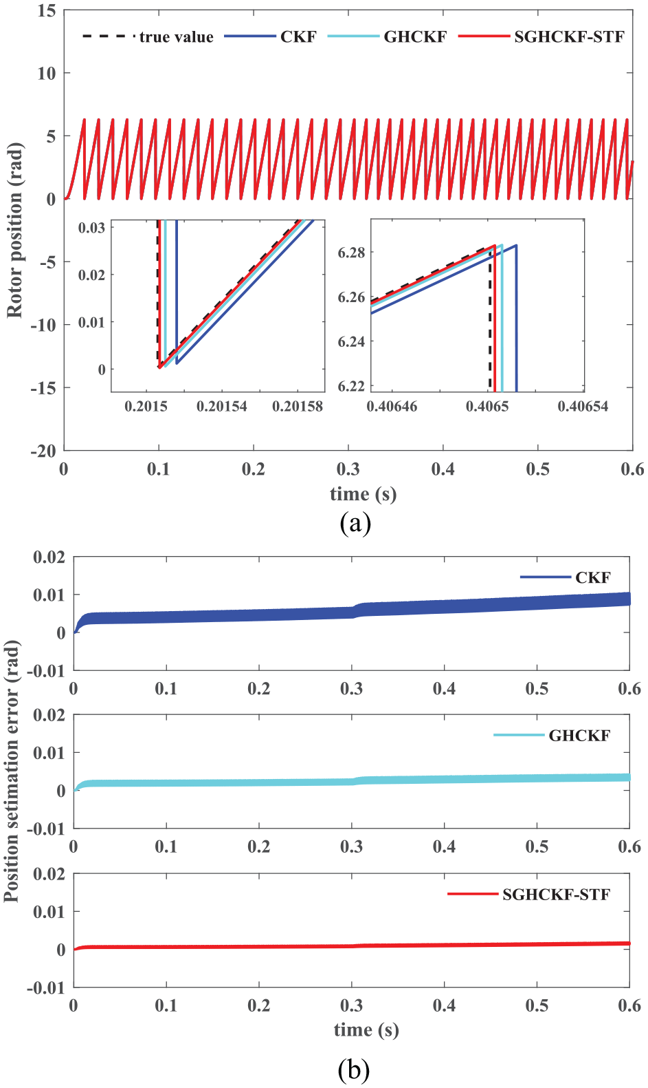
Rotor position estimation comparison curve under a sudden change in speed: (a) rotor position estimation and (b) estimation error.
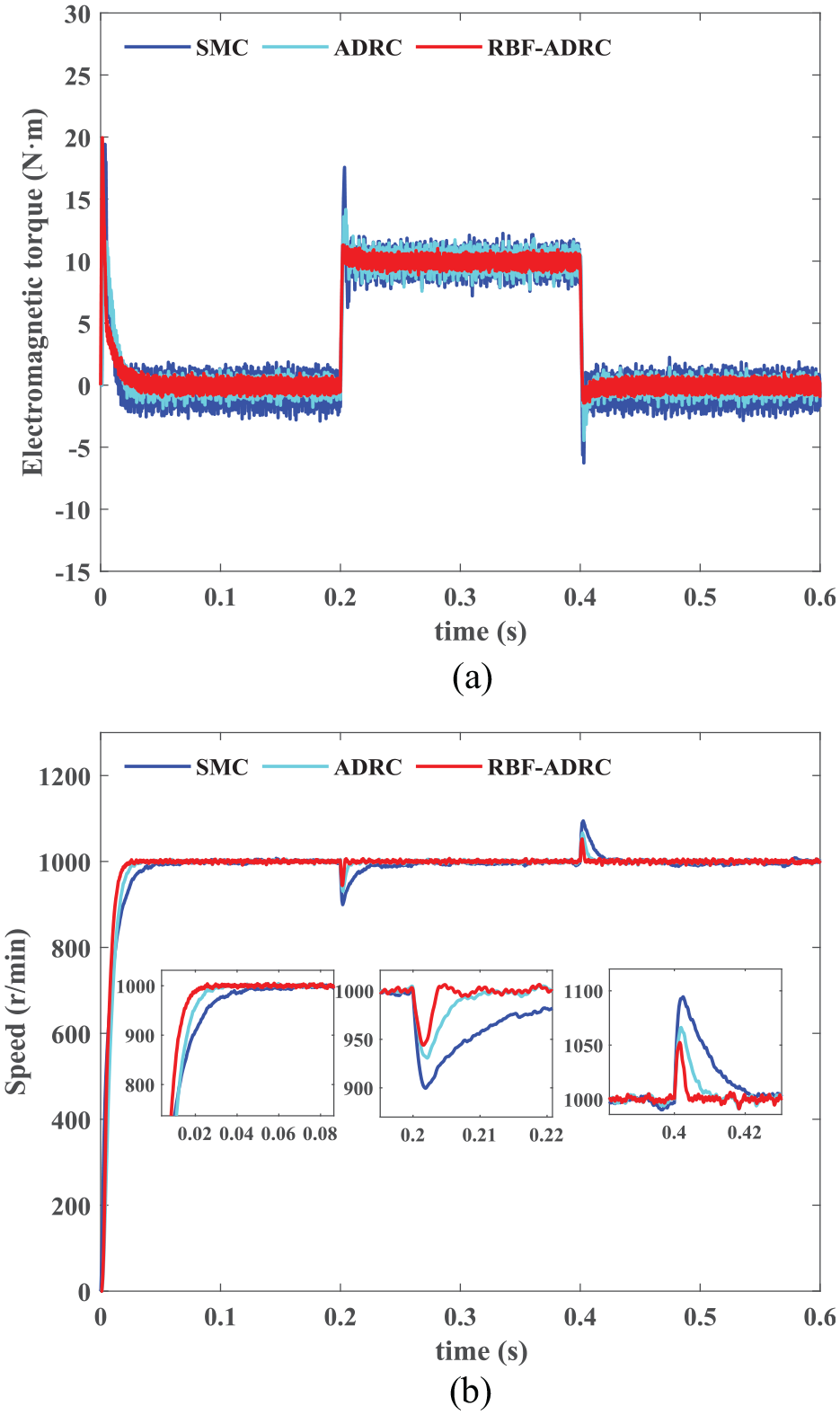
electromagnetic torque and speed control comparison curves under the sudden load: (a) electromagnetic torque and (b) speed.
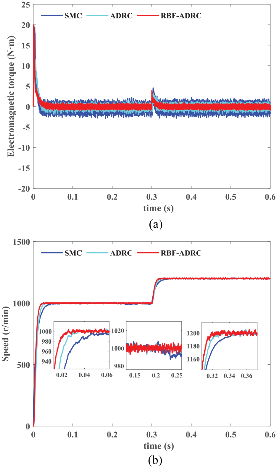
electromagnetic torque and speed control comparison curves under a sudden change in speed: (a) electromagnetic torque and (b) speed.
SGHCKF-STF algorithm estimation experiment
Condition 1. Sudden load
The target speed set to 1000 r/min, and 10 N · m load torque is suddenly applied in the opposite direction when t = 0.2 s and t = 0.4 s. The estimated speed and rotor position curves of the three algorithms and their corresponding error comparison curves are shown in Figures 7 and 8.
Figure 7 shows the speed estimation of PMSM using the CKF, GHCKF, and SGHCKF-STF algorithms and their estimation error comparison curves, respectively. It is obvious that the estimated values of the three algorithms can be quickly tracked and stabilized to the true value. But overall, the SGHCKF-STF algorithm tracked the best. When the load is suddenly applied, it can be seen from the speed estimation error comparison that the CKF speed estimation error jumps from 0.2 to 0.5 r/min, the GHCKF jumps from 0.1 to 0.3 r/min, while the SGHCKF-STF only jumps from 0.05 to 0.1 r/min, it shows that the SGHCKF-STF algorithm has higher estimation accuracy overall than the CKF and GHCKF algorithms.
Figure 8 shows the rotor position estimation of PMSM using the CKF, GHCKF and SGHCKF-STF algorithms and their estimation error comparison curves, respectively. It is evident that the three algorithms can accurately estimate the rotor position. Compared with the CKF and GHCKF algorithms, the SGHCKF-STF algorithm has a smaller estimation error. The comparison curves of the estimation error of the rotor position show that the estimation errors of the CKF and GHCKF algorithms become larger and the estimation effects become worse after the sudden addition of load due to the perturbation of the system and the accumulation of the filtering error. In contrast, the SGHCKF-STF algorithm still maintains a small estimation error. This shows that the SGHCKF-STF algorithm has better estimation accuracy and stability.
Condition 2. Sudden change in speed
The motor speed first reaches 1000 r/min and suddenly changes to 1200 r/min at 0.3 s. The estimated speed and rotor position curves of the three algorithms and their corresponding error comparison curves are shown in Figures 9 and 10.
Figure 9 shows the speed estimation of PMSM using the CKF, GHCKF, and SGHCKF-STF algorithms and their estimation error comparison curves, respectively. When the speed change occurs suddenly, the estimation error increases to 0.4 r/min for the CKF, 0.2 r/min for the GHCKF, and only 0.1 r/min for the SGHCKF-STF. When the system is stabilized, the estimation error returns to a stable value. It is clear that the estimation error of the SGHCKF-STF algorithm is least affected throughout the speed variation, and it can always maintain a small estimation error.
Figure 10 shows the rotor position estimation of PMSM using the CKF, GHCKF, and SGHCKF-STF algorithms and their estimation error comparison curves, respectively. It can be seen that compared with the CKF and GHCKF, the SGHCKF-STF algorithm still has smaller estimation error. When the speed changes suddenly, the position errors of the three algorithms increase, but the estimation error of SGHCKF-STF algorithm changes the least. The SGHCKF-STF algorithm has a good tracking effect, and the application of the SGHCKF-STF algorithm to sensorless control can improve the control accuracy of the PMSM.
To further compare the accuracy of filtering algorithms, under sudden load and sudden in speed change conditions, the mean absolute error (MAE) and root mean square error (RMSE) between the estimated values of the three algorithms and the true values are compared. The MAE and RMSE formulas are:
where
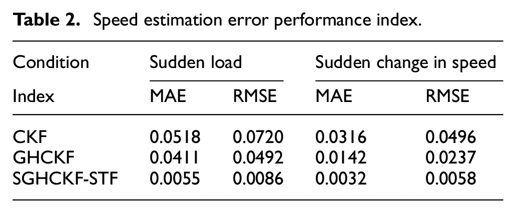
The comparison results between MAE and RMSE are shown in the Tables 2 and 3.
Speed estimation error performance index.
Rotor position estimation error performance index.
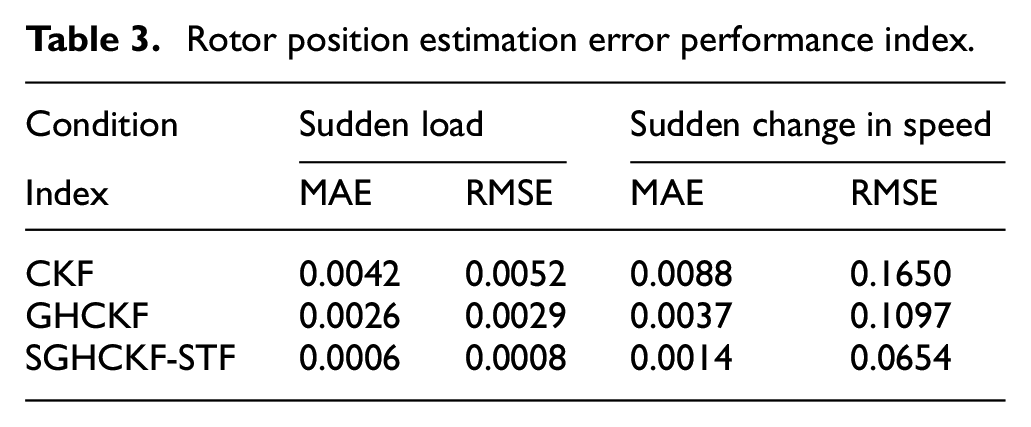
It is evident that from Tables 2 and 3 that the SGHCKF-STF algorithm greatly improves the estimation accuracy of speed and rotor position. Under condition 1, compared with the CKF and GHCKF algorithms, the SGHCKF-STF algorithm improves the estimation accuracy of the speed by 89.38% and 86.61% in the MAE, and by 88.05% and 82.52% in the RMSE, respectively, the estimation accuracy of the rotation position by 85.71% and 76.92% in the MAE, and by 84.61% and 72.41% in the RMSE, respectively. Under condition 2, compared with the CKF and GHCKF algorithms, the SGHCKF-STF algorithm improves the estimation accuracy of the speed by 89.87% and 77.46% in the MAE, and by 88.31% and 75.53% in the RMSE respectively, the estimation accuracy of the rotation position by 84.09% and 62.16% in the MAE, and by 60.36% and 40.38% in the RMSE, respectively. It shows that the SGHCKF-STF algorithm has higher numerical stability and accuracy, and the use of the SGHCKF-STF algorithm in PMSM sensorless control can satisfy the demands of accurate PMSM control.
RBF-ADRC sensorless control experiment
For evaluating the performance of sensorless control for the PMSM, three sensorless control methods with SMC, ADRC, and RBF-ADRC control strategies are used for experimental verification under two operating conditions of sudden load addition and sudden speed change.
Condition 1. Sudden load
Figure 11 shows the experimental comparison curves of electromagnetic torque and speed control under SMC, ADRC, and RBF-ADRC control strategies, respectively.
Condition 2. Sudden change in speed
Figure 12 shows the experimental comparison curves of electromagnetic torque and speed control under SMC, ADRC, and RBF-ADRC control strategies, respectively.
Figures 11(a) and 12(a) show the comparison curves of electromagnetic torque under two working conditions, respectively. It can be seen that when the PMSM is started, the amplitude of oscillation generated by RBF-DRC is significantly smaller than that of SMC and ADRC. From Figure 11(a), after increasing the load at 0.2 s, all three control strategies can respond quickly, but the overshoot generated by RBF-ADRC response to the target torque is the smallest. It can be seen that the robustness and self-anti-disturbance capability of control with RBF-ADRC is stronger and enhances the stability of torque control compared with SMC and ADRC.
Figures 11(b) and 12(b) show the comparison curves of the speed control effects of the three control strategies without sensors under two operating conditions, respectively. From Figure 11(b), the three control strategies can reach the target speed without overshoot, and the response is most rapid under the RBF-ADRC control strategy, which stabilizes at the target speed in about 0.02 s and takes a shorter time to reach steady state, while SMC and ADRC reach steady state in about 0.03 and 0.06 s. When a load torque is suddenly applied, the overshoot generated under RBF-ADRC control is 5%, and the time to restore to steady state is 0.004 s. However, the overshoot is large under SMC and ADRC control, and the time to restore to steady state is long. From Figure 12(b), in the case of sudden speed changes, the time taken to reach the target speed under RBF-ADRC control is smaller and the response is faster. It can be seen that RBF-ADRC control is more adaptive and robust than SMC and ADRC. In summary, the RBF neural network can not only improve the anti-load interference ability of ADRC, but also enhance the adaptability of the system.
The above experiments illustrate that the SGHCKF-STF algorithm can estimate the speed and rotor position of the PMSM more accurately than the CKF and GHCKF, and the RBF-ADRC effectively improves the self-anti-disturbance capability and control accuracy of the ADRC by adaptively adjusting the ADRC parameters online. It can be seen that the PMSM sensorless control method based on RBF-ADRC and SGHCKF-STF algorithm has better control effect.
Conclusion
In this paper, the designed SGHCKF-STF algorithm is used to estimate the speed and rotor position of the PMSM, compared with the CKF and GHCKF estimation results, the accuracy of the SGHCKF-STF algorithm for estimating the speed and rotor position is significantly improved. By the experimental analysis of RBF- ADRC sensorless control, it is obtained that compared with SMC and ADRC, the response speed of RBF- ADRC is improved by 48.57% and 28.59%, and the control accuracy is improved by 9.82% and 4.36% under the Condition 1, the response speed of RBF- ADRC is improved by 57.14% and 30.23%, and the control accuracy is improved by 12.63% and 6.87% under the Condition 2. Thus, it can be seen that the PMSM sensorless control method based on RBF-ADRC and SGHCKF-STF algorithm can not only save costs to a certain extent, but also effectively improve the control accuracy and self-disturbance rejection ability of PMSM.
Footnotes
Declaration of conflicting interests
The author(s) declared no potential conflicts of interest with respect to the research, authorship, and/or publication of this article.
Funding
The author(s) disclosed receipt of the following financial support for the research, authorship, and/or publication of this article: This work was supported in part by the National Natural Science Foundation of China (Grant No. 51605003 and 51575001), the Natural Science Foundation of the Anhui Higher Education Institutions of China (KJ2020A0358), young and middle-aged top talents training program of Anhui Polytechnic University.