
Abstract
To improve the load-bearing capacity and the rotation range about the normal of the moving platform in a spherical parallel mechanism (SPM), a type synthesis method for spherical hybrid mechanisms (SHMs) with fixed centers of rotation is proposed by coupling a serial transmission chain with the central passive limb chain of the SPM near its center area. Based on the analysis of the spherical mechanism configuration’s research status with a fixed rotation center, a method for systematically synthesizing SHMs is given, and four types of limb chains are developed. The possible limb constraint systems provided by each type of limb chain are analyzed via screw theory, and the type synthesis of each type of limb chain is carried out. Screening rules are proposed to obtain the preferred limb chains from the limb chain configuration results. By selecting and permuting preferred limb chains based on the mechanism’s center position of rotation and the constraint type, a series of SHMs that rotate unrestricted about the normal of the moving platform are produced. Selecting the RBR-2RRR SHM as an example, its workspace, singularity, dexterity, and stiffness are analyzed to verify the effectiveness of the research. This work enriches the configuration types of SHMs and provides theoretical support for the design and applications of SHMs in engineering.
Keywords
Introduction
The 3-DOF spherical mechanism is used to attain three-dimensional rotation and has wide applications in fields such as space pointing mechanisms, bionic joints, and medical rehabilitation. The parallel and hybrid configuration schemes have advantages such as high precision, high stiffness, and high dynamic motion compared with the serial configuration and have always been a research hotspot that attracts much attention from academia and industry.
Many scholars have conducted in-depth and extensive research on the configuration of the spherical parallel mechanism (SPM). Gosselin first proposed a camera positioning mechanism named Agile Eye 1 (the topological structure is a 3-RRR overconstrained SPM). Karouia and Hervé 2 obtained three classes of non-overconstrained SPMs, 3-P l RR, 3-RP l R, and 3-RRP l , by replacing one R pair in the RRR limb chain with a P l pair (where P l denotes a planar pair or planar sub-chain). Di Gregorio 3 and Karouia and Hervé 4 obtained four types of non-overconstrained SPMs, 3-RUU, 3-RCC, 3-CRC, and 3-CCR, by adding an inactive rotation pair and inactive prismatic pair to the RRR limb chain. Fang and Tsai 5 carried out the type synthesis of 3-limb chain symmetrical non-overconstrained SPMs based on screw theory and obtained typical mechanisms, including 3-RRS, 3-RSR, 3-URU, 3-URC, 3-UPC, and 3-CRC. Kong and Gosselin 6 synthesized symmetrical SPMs with and without inactive kinematic pairs in the limb chain based on screw theory. Karouia and Hervé 7 synthesized nonsymmetrical non-overconstrained SPMs based on group theory.
By changing one of the revolute pairs in the RRR limb chain to a circular arc-shaped prismatic pair Pc, in which the virtual axis is coaxial with the replaced R pair, a new mechanism configuration can be obtained. By varying the different numbers and positions of substitutions, three major classes (RRPc, RPcPc, PcPcPc) and a total of seven basic limb kinematic chains can be obtained. By analogy, PcRS, PcSR, RPcS and other limb kinematic chains can be obtained. Specifically, Sui et al. 8 synthesized three types of SPMs: 3-RRPc, 3-PcRR, and 3-PcRPc. Moreover, Zhao et al. 9 proposed a 2RPcR-RRPc SPM, Zarkandi10,11 proposed two 3-PcRR SPMs, and Zhao et al. 12 proposed a 3-PcPcR SPM.
In addition, scholars have proposed using the spherical pair as the main bearing chain of the SPM and carrying out type synthesis with the purpose of improving its rigidity. The configurations visible in the literature include 3-PUS/S, 13 3-PSU/S, 14 3-PSS/S,15,16 3-UPS/S, 17 3-SPS/S,18,19 and 3-UCU/S. 20
The abovementioned SPMs have one important characteristic in common: they cannot rotate unrestricted about the normal direction of the moving platform, which limits the SPM’s use in applications such as active ball joints or positioning platforms for machining tools (such as milling or drilling). To give the mechanism a rotation capability of more than a full cycle, two solutions can be implemented based on different configuration principles:
Adopting a coaxial input spherical parallel configuration scheme
The initial revolute pair in the 3-RRR, 3-RSR, and 3-RRS mechanism limb chains is arranged with a coaxial input or changed to a circular arc-shaped prismatic pair. When an appropriate input drive is used, the mechanism’s moving platform can rotate about its normal without being limited, but this scheme has higher requirements for drive coordination control. The mechanisms seen in the literature are 3-RRR, 21 3-RSS, 22 3-PcRR, 23 3-PcSR, 24 3-PcRS, 25 3-PcUS/S, 26 and 3-PcSS/S. 27
Adopting a spherical hybrid configuration scheme
Xu et al. 28 proposed a 3-UPS/S+R spherical hybrid mechanism (SHM). The terminal rotation motion is driven by a lateral transmission chain. In addition, some scholars have proposed central transmission SHMs. Specifically, Zhang, Hess Coelho, and Du proposed SHMs with topological structures of 2RPc-2RPcS-RUR, 29 3RRR-RUR, 30 and UPR-UCU-URU, 31 respectively, for use in underwater vector propulsion devices. Bajaj and Dollar 32 proposed a PRU-PSS-RUR SHM for wrist joints. Wu and Zou 33 proposed three types of SHMs with topological structures of 2RRR-RPS-RUR, 2UPU-RPS-RUR, and 2CUU-RPS-RUR for active ball joints or machine tool machining tool heads. However, at present, U-pairs are mostly used in transmission chains, which exhibit periodic fluctuations 34 that can cause vibration and wear during motion transmission.
SHMs inherit the characteristics of compact structure, high rigidity, and high precision from parallel mechanisms while possessing complete cycle rotation capabilities that general parallel mechanisms do not have. At present, there is still potential for further exploration of the configuration types of SHMs. Exploring new types of SHMs is very significant for expanding the application range of spherical mechanisms in engineering fields.
In this paper, a type synthesis method is proposed for SHMs with fixed rotation centers by coupling a serial transmission chain with the central passive limb chain of the SPM near the center area of the SPM. Based on the analysis of the spherical mechanism configuration’s research status with a fixed rotation center, a method for systematically synthesizing SHMs is given, and four types of limb chains are developed. Based on screw theory, the possible limb constraint systems provided by each type of limb chain are analyzed, and the type synthesis of each type of limb chain is carried out. Screening rules are proposed to obtain the preferred limb chains from the limb chain configuration results. Depending on the difference in the mechanism’s center position of rotation and the constraint type, a series of SHMs that rotate unrestricted about the normal direction of the moving platform are produced by selecting the corresponding preferred limb chain for permutations and combinations.
Constraint-synthesis method based on screw theory and synthesis ideas for SHMs
Constraint-synthesis method based on screw theory
In screw theory,
35
any screw can be represented as
If two screws

In this case,
All possible motion forms of the end component in space are linear combinations of all the kinematic screws

The linear space composed of all kinematic screws
If there is a set of screws

The type synthesis method based on screw theory 35 is as follows: First, according to the kinematic screw system of the target mechanism, the mechanism constraint system can be obtained, and the number of limb chains and each limb constraint system can be determined. Second, according to the limb constraint system, the limb screw system can be obtained and used for the type synthesis of the limb chain. Finally, the obtained limb chains can be assembled according to certain geometric requirements to obtain the final mechanism configuration and verify the non-instantaneity of the mechanism.
Synthesis ideas for SHMs
As shown in Figure 1, the SHM can be seen as an integrated coupling between a central transmission limb chain in a series configuration and an SPM (with 2 or 3 DOFs) with a central ball pair passive limb chain by sharing the same rotational center.
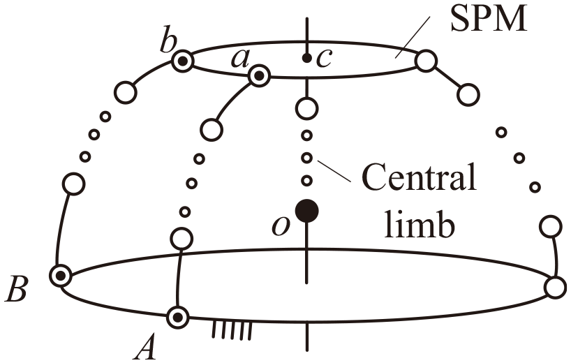
Composition schematic of an SHM.
Among them, the central transmission limb chain has two swing DOFs and one full-cycle rotation DOF. It exists both as a series mechanism and as a passive limb chain of a parallel mechanism. The advantages of this coupling design are as follows: (1) the drive that controls the rotation of the end can be arranged close to the fixed platform to reduce the end load and improve dynamic performance; (2) the central transmission limb chain can be used as the central passive limb chain of the SPM for external force unloading and improving the linear displacement stiffness of the mechanism; and (3) the design makes full use of the blank area near the center of the SPM to improve the space utilization rate of the mechanism.
When the parallel part mechanism has 2 DOFs, the central S-pair passive limb chain does not constrain the rotation motion of the mechanism. Therefore, there must be a constraint limb chain that constrains the rotation of the moving platform about its normal. As shown in Figure 1, the constraint limb chains that make the four points Aoca always coplanar (first type coplanar constraint) are defined as type I limb chains, and the constraint limb chains that make the four points BAab always coplanar (second type coplanar constraint) are defined as type II limb chains. Type I and type II limb chains can eliminate the rotation DOF of the moving platform about its normal through their respective coplanar constraints. In addition, if the moving platform has a definite motion, it must also have a non-constraint limb chain. The limb chains that do not constrain the rotation of the moving platform about its normal are defined as type III limb chains. Type III limb chains may not provide any constraint but may also provide an overconstraint that is the same or partially the same as that of the central S-pair passive limb chain. When the parallel part mechanism has 3 DOFs, there are at least three type III limb chains in the mechanism, and there are no type I or type II limb chains.
The synthesis idea is as follows: First, the SHM can be deconstructed into a series mechanism and an SPM with a central S-pair passive limb chain. Second, in the serial part, the central transmission limb chain’s configuration can be synthesized according to its DOFs and task requirements. Third, in the parallel mechanism part, all possible limb constraint systems provided by type I, type II, and type III limb chains can be analyzed according to the constraint task of the limb chain, the corresponding limb screw systems can then be solved, and type synthesis for various types of limb chains can be carried out. Finally, the obtained central transmission limb chain and type I, type II, and type III limb chains can be reasonably configured to obtain an SHM configuration that meets the requirements.
Synthesis and preferred selection of limb chains
Symbol description
To more clearly describe the synthesized limb chain types, the following rules are established: The symbol main body represents the type of kinematic pair, where R, P, C, U, and S represent a revolute pair, prismatic pair, cylindrical pair, universal joint, and ball joint, respectively. The upper left or upper right symbols represent the direction of the R-pair centerline or P-pair. The lower left or lower right symbol indicates that the kinematic pair axis must pass through this point. Moreover, i, j, and k represent arbitrary directions of the spatial axes.
For example,
The focus of limb chain synthesis in this article is on basic kinematic pairs and commonly used multi-DOF kinematic pairs. The helical pair H and the circular arc-shaped prismatic pair Pc are not studied in this paper.
Synthesis of central transmission limb chains
Unequal speed central transmission limb chain
The central transmission limb chain needs to meet two conditions: Condition 1 is to constrain the moving platform of the parallel mechanism to generate spherical motion about point o; and Condition 2 is to transmit a rotational motion through the fixed platform and the moving platform of the parallel mechanism to the end of the hybrid mechanism.
According to Condition 1, the moving platform can be connected to the fixed platform through an S-pair. According to Condition 2, for the central limb chain to transmit rotational motion, the S-pair can be changed to a U-pair, and the R-pair can be set at the connection between the central limb chain and the fixed platform and the moving platform of the parallel mechanism to obtain the

Central transmission limb chain: (a)
Constant velocity central transmission limb chain
By replacing the U-joint in the
Synthesis of type I limb chains
Figure 3 is a partial view of a 2-DOF SPM with a central S-pair passive limb chain. The fixed and moving platforms are fixed to the fixed coordinate system

Possible constraint types provided by the type I limb chain.
Case 1: A constraint force couple
In this instance, the limb chain provides a constraint force couple
In the limb coordinate system with
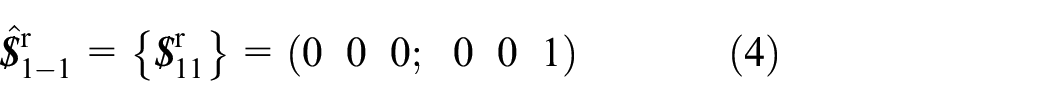
The reciprocal screw for

According to equation (2), by linearly combining the basic screws in
Configuration of the type I limb chains in Case 1.
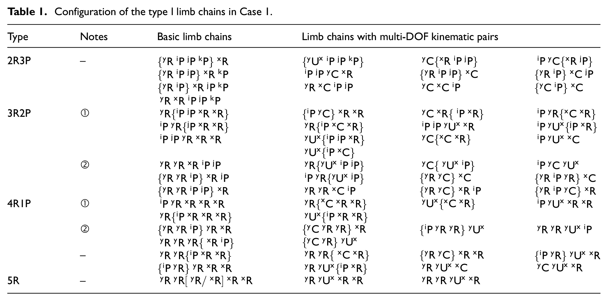
To save space, two symbols, {} and [], are used in this article to represent limb chains. The first symbol, {}, represents any possible arrangement of the elements in {}, while [] indicates that only one element in [] is taken. For example,
Case 2: A constraint force
In this instance, the limb chain provides a constraint force
In the limb coordinate system with N as the origin, the following expression can be obtained:

According to equation (1), the limb screw system

where
By linearly combining
Configuration of the type I limb chains in Case 2.

Case 3: A constraint force couple
or a constraint force
, depending on the instantaneous spatial position of the limb chain
Although the spatial orientations of the constraints in the above two situations change with the motion of the moving platform, the nature of the constraints does not change. In this section, the following situation is discussed: the constraint properties provided by the limb chain switch between the constraint force
To provide a clearer explanation of the process of switching constraint properties, the

Transformation of the constraint force and constraint couple.
Configuration of the type I limb chains in Case 3.

Case 4: Both a constraint force couple
and a constraint force
In this instance, in the limb coordinate system with N as the origin, the following expression can be obtained:

After calculating the reciprocal screw for

Similarly, by linearly combining
The type I limb chains in Case 4.

Case 5: Three orthogonal constraint forces
,
, and
passing through point o and a constraint force couple
In this instance, the limb screw system of

The limb chain configuration obtained is
Case 6: A constraint force couple
and any one or two constraint forces from
,
, and
By obtaining the limb screw system and taking linear combinations, the following basic limb kinematic chains can be obtained:

Due to the presence of the inactive prismatic pair (which does not move when the moving platform rotates), the above limb chains are not adopted. By further combining the above basic limb kinematic chains, the effective limb chain configurations
Synthesis of type II limb chains
As shown in Figure 1, Type II limb chains ensure that points A, B, b, and a are coplanar (second type coplanar constraint), eliminating the rotational DOF of the moving platform about its normal. Figure 5 shows the front view of the plane ABba. AB and ab are line segments on the fixed platform and the moving platform, respectively. It is assumed that

Kinematic constraints on ab.
To ensure that ab and AB remain coplanar, the type II limb chain needs to provide a constraint force

Linearly combining the basic screws in
Configuration of type II limb chains.

Synthesis of type III limb chains
Type III limb chains do not affect the rotational DOF of the moving platform, so they either only provide overconstraints that are the same or partially the same as those provided by central passive limb chain or do not provide any constraints at all. As shown in Figure 6,
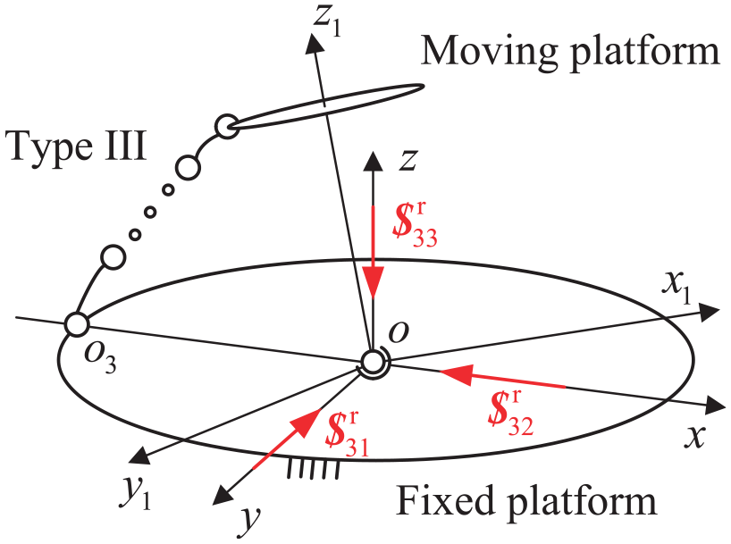
Possible constraint types provided by the type III limb chain.
Case 1: A constraint force
that always passes through point o
In this instance, the limb chain provides a constraint force
Three revolute pair axes passing through point o
Linearly combining the basic screws can obtain limb chain configurations such as
Two revolute pair axes passing through point o
In this case, the axes of the revolute pairs in the limb chain intersect at point o or are parallel to the constraint force
Configuration of the type III limb chains in Case 1.

Case 2: Two constraint forces
and
that always pass through point o
In this instance, the limb chain provides two constraint forces passing through point o. The limb screw system can be easily obtained as follows:

Linearly combining the basic screws in
Case 3: Three constraint forces
,
, and
that always pass through point o
In this instance, the limb chain provides three constraint forces
Case 4: No constraints are provided
In this instance, the limb chain does not provide any constraints on the moving platform, that is, it is an unconstrained limb chain. The widely used unconstrained limb chains are
Limb chain screening principle
In the above text, we used screw theory to synthesize the limb chain configurations corresponding to different constraint conditions. In this section, we formulate some optimization rules to screen out limb chain configurations with simple compositions and reasonable layouts. The details are provided in the following discussion:
(1) Two bar-three pair or three bar-four pair limb chains containing multi-DOF kinematic pairs (C, U, S) should be preferred. Limb chains composed of basic kinematic pairs often have disadvantages such as many components, complex forms, and self-interference. Replacing basic kinematic pairs with multi-DOF kinematic pairs can reduce the total number of components in a limb chain and simplify its complexity.
(2) The limb chain should contain only one driving joint and should be as close to the fixed platform as possible. An excessive number of driving devices matched with driving pairs will increase the mechanism’s inertia constant and reduce its dynamic characteristics. In addition, placing the drive joint close to the fixed platform can reduce the limb chain’s center of gravity height, thereby improving the mechanism’s dynamic performance. In the selection of driving joints, the revolute pair R can be used as a driving pair or passive pair. The U-pair and S-pair are passive pairs. The P-pairs are mostly used as driving pairs. When used as a passive pair, it often needs to be equipped with a guiding mechanism to avoid motion jamming.
(3) The limb chain should minimize space occupation and have a simple layout. Limb chains composed of the same kinematic pairs with different arrangements can have completely different occupation effects during movement. For example,
Based on the above screening conditions, the preferred limb chains are shown in Table 7, where joints with underlines ¯ are driving joints.
Preferred limb chains.

Type synthesis of SHMs
Based on the aforementioned analysis, a series of SHM configurations can be obtained by assembling the limb chains presented in Table 7 under certain conditions. According to the different positions of the rotation center in the mechanism, SHMs can be classified into two types: SHMs with a rotation center close to the fixed platform and those with a rotation center close to the moving platform.
Selection and spatial distribution of limb chains
Collating the obtained types reveals that the spatial distribution of SHM limb chains can be classified into three categories, as shown in Figure 7.

The spatial distribution of outer limb chains: (a) type I and II limb chains, (b) type II and III limb chains, and (c) only type III limb chains.
The limb chain composition types corresponding to each spatial layout are as follows:
(1) The outer limb chains are type I and type III limb chains (Figure 7(a)), in which type I limb chains make Aoca four-point constant coplanar and constrain the redundant rotational DOF of the SPM moving platform, and type III limb chains provide another driving input needed for stable motion of the mechanism. The assembly conditions between these chains are as follows:① The origin points
(2) The outer chains consist of type II and type III limb chains (Figure 7(b)). The type II limb chain ensures that the four points ABba remain coplanar, thereby eliminating redundant rotational DOF in the SPM moving platform. The type III limb chain provides an additional drive input necessary for stable motion of the mechanism. The assembly conditions between these limb chains are as follows:
④ The axes of the starting and ending revolute pairs of the type II limb chain are arranged on a set of parallel straight lines AB and ab (AB and ab are located on the fixed and moving platforms of SPM, respectively), and each kinematic pair is arranged in the direction specified by its superscript and subscript. Only unconstrained limb chains in the type III limb chain can be arranged within the plane ABba, while the remaining type III limb chains are still arranged in the direction specified by their superscript and subscript. ⑤ The spatial layout of the limb chain is generally shown in Figure 7(b), and the specific structural parameters need to be determined through dimensional synthesis of ad, cd, AD, oD, and oc.
(3) All three outer limb chains consist of a type III limb chain (Figure 7(c)), which forms the requested SHM by coupling with the center limb chain. The distribution of the limb chains is as follows: ⑥ evenly distributed circumferentially.
In addition, in all three cases mentioned above, the following conditions are met: ⑦ Both ends of the central limb chain pass through the fixed and moving platforms of the SPM and are connected to them through a revolute pair. The rotation center of the U-pair or B-pair coincides with the rotation center of the SHM.
Type synthesis of the rotation center close to the fixed platform
When the rotation center is arranged close to the fixed platform, the mechanism can have a larger swing radius and swing line displacement space. By arbitrarily selecting central limb chains (CLCs), type I, type II, and type III limb chains from Table 7 and arranging and combining them according to the limb chain composition and assembly conditions shown in Table 8, a series of SHMs with rotation centers close to the fixed platform can be obtained. The typical configurations and their examples are shown in Table 8 and Figures 8 to 10.
Limb chain composition, assembly conditions, and typical configurations.

Examples of the SHMs containing type I limb chains: (a) RUR-SRR-SRU, (b) RUR-URR-URS, (c) RBR-RR-RRR, (d) RBR-UCR-UCU, (e) RBR-SPR-UPS, and (f) RBR-UPR-UPS.

Examples of the SHMs containing type II limb chains: (a) RBR-UPU-UPS, (b) RUR-URU-URS, and (c) RBR-2UPU.

Examples of the SHMs containing type III limb chains only: (a) RBR-3RSR, (b) RBR-3RRR, and (c) RBR-3UCU.
Type synthesis of the rotation center close to the moving platform
By arranging the rotation center close to the moving platform, new configurations can be obtained. At the same time, the rotation radius decreases, and the mechanism theoretically has better dynamic characteristics. The synthesis process is the same as before and involves first selecting limb chains based on the screening principle and then arranging and combining them to obtain the target configuration.
Preferred limb chain configurations
Based on the synthesized limb chains and combined with the established screening principle, the preferred limb chains can be obtained when the rotation center is close to the moving platform, as shown in Table 9.
Preferred limb chains when the rotation center is close to the moving platform.

Type synthesis
By arbitrarily selecting central limb chains (CLCs), type I, type II, and type III limb chains from Table 9 and arranging and combining them according to the limb chain composition and assembly conditions shown in Table 10, a series of SHMs with rotation centers close to the moving platform can be obtained. The typical configurations and their examples are shown in Table 10 and Figures 11 to 13.
Limb composition, assembly conditions, and typical configurations.


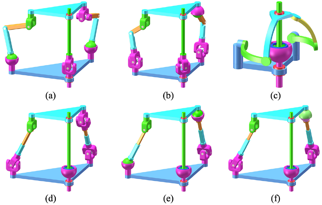
Examples of the SHMs containing type I limb chains: (a) RBR-RCU-UCU, (b) RBR-RPU-SPU, (c) RUR-PRS-PUS, (d) RBR-PRU-PUS, (e) RBR-CRU-CUU, and (f) RBR-RRU-RSU.

Examples of the SHMs containing type II limb chains: (a) RBR-UPU-UPS, (b) RUR-URU-URS, and (c) RBR-2UPU.

Examples of the SHMs containing type III limb chains only: (a) RBR-3RUS, (b) RUR-3PUS, and (c) RBR-3CUU.
Characteristics of various configurations
(1) From the perspective of the central limb chain: The rotational speed transmitted by the RUR limb chain is not uniform, and periodic fluctuations occur, 34 making it difficult to accurately control the angular displacement of its rotation during spatial motion. The configuration using such a limb chain can be used for situations with low transmission torque (due to the lower stiffness of the U-pair) and low-precision control of the output angular displacement and angular velocity. The ball cage joint has the advantages of a high transmission torque, strong tensile and compressive strength, constant speed transmission, and easy control, making the RBR limb chain an excellent transmission and unloading limb chain. Such limb chains can be used in scenarios with high transmission torque and high-precision control of the output angular displacement and angular velocity. (2) From the perspective of the position of the rotation center: When the rotation center is close to the fixed platform, the mechanism has a large rotation radius and a large linear displacement space. When the rotation center is close to the moving platform, the rotation radius of the mechanism decreases, and the dynamic performance is enhanced. (3) From the perspective of constraint type: The configuration obtained based on the first type of coplanar constraint exhibits partial kinematic decoupling because the rotation axis of the first type of coplanar constraint is the y-axis and the rotation around the y-axis is only controlled by the type III limb chain. The configuration obtained based on the second type of coplanar constraint shows decoupling only for the motion of the central limb chain. However, when the mechanism is only composed of a central transmission limb chain and two type II limb chains, the mechanism can be subject to more overconstraints that restrict the rotation of the moving platform with the minimum number of limb chains, thus yielding greater structural stiffness. The configuration with only type III limb chains uses a uniform distribution of the same limb chains, and its performance is characterized by central symmetry in spatial distribution. The recommended configurations from different perspectives are shown in Table 11. Users can select appropriate configurations from the corresponding classification based on the characteristics of the application scenario.
Recommended configurations from various perspectives.

An example of the obtained SHMs
Figure 14 shows a RBR-2RRR SHM that can be used for vector propulsion devices or human biomimetic joints. The coordinate systems o-XYZ and o-xyz are established with the rotation center of the mechanism as the origin. The initial attitudes of the two coordinate systems coincide and are fixedly connected to the fixed platform and the moving platform. The Z-axis is perpendicular to the fixed platform upwards, and the X-axis is located in the plane where the Z-axis and rotation axis
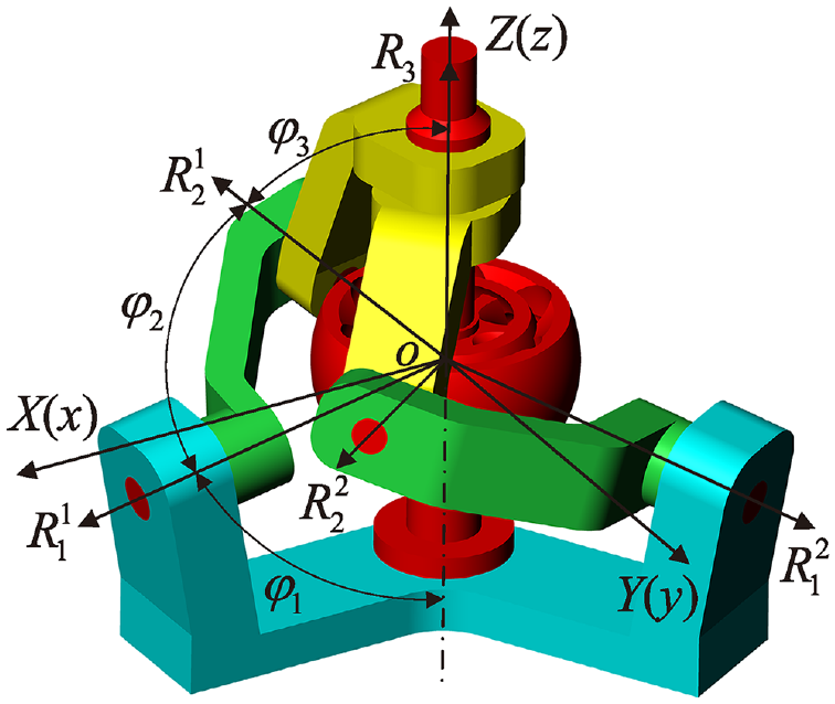
Structural parameters of RBR-2RRR.
Inverse kinematics and simulation verification
The global coordinates of
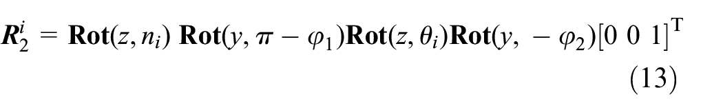

where
From the geometrical relationship between the revolute pairs

Substituting equations (13) and (14) into equation (15) yields the following expression:

where
In the central limb chain, the output shaft and input shaft do not rotate relative to each other. Therefore, the output shaft needs to rotate

Next, the correctness of the inverse kinematics solution is verified through virtual prototype simulation in ADAMS. The parameters of the output axis attitude angle are set to

Input angle
Singularity and workspace analysis
Limb singularity and platform singularity
37
occur in the RBR-2RRR mechanism. The condition for limb singularity to occur is that the revolute pairs

Singularity and workspace: (a) the first type of limb singularity, (b) the second type of limb singularity, (c) the first type of platform singularity, (d) the second type of platform singularity, and (e) the singular configuration and workspace.
If we want the workspace to avoid limb singularity and platform singularity, the structural parameters of the RBR-2RRR mechanism need to meet the following conditions:


where
The target workspace is set to
Dexterity analysis
By taking the derivative of equations (15) and (17), the following expression can be obtained:

where
To this end, the kinematic Jacobian matrix of the mechanism is expressed as follows:

where
The condition numbers of the Jacobi matrix, 38 the kinematic conditioning index, 38 and the global conditioning index 39 of the mechanism are respectively represented as follows:


The distribution of
Stiffness comparison
The deformation response of the RBR-2RRR mechanism and the 3-RRR mechanism to the same load is compared in this section utilizing the ANSYS static analysis module. The comparison demonstrates that the proposed type synthesis method can enhance the stiffness of the spherical mechanism.
In the modeling stage, the structural parameters of the RBR-2RRR mechanism are consistent with those in section “Singularity and workspace analysis.” The 3-RRR mechanism adopts the second set of structural parameters optimized for stiffness in Table 1 of the literature. 40 Specifically, the angle between adjacent revolute pairs is 90°, and the angle between the revolute pairs’ axes on the moving platform and the fixed platform and the normal of the platform is 60°. The width and thickness of the limb chains and the rotation shaft radius of the revolute pair are the same in the two mechanisms.
The settings in the ANSYS static analysis module are as follows: the materials for all components are structural steel, except for the outer race, inner race, steel ball, and cage in the ball cage joint, which are 42CrMo, 42CrMo, GCr15, and 20CrMnTi, respectively. The starting revolute pair of each limb chain is bound to the fixed platform, and the contact between the other revolute pairs is set to no separation. The contact between the inner and outer surfaces of the cage is set to be frictionless, and the contact between the steel ball and the inner and outer raceways of the ball cage joint is set to be friction contact with a friction coefficient of 0.1. The unit size is 2 mm, and automatic mesh generation is performed. Finally, a perpendicular load of 2000 N is applied to the moving platforms of both mechanisms.
As shown in Figure 18(a), the maximum deformation of the RBR-2RRR mechanism is 0.03 mm, which occurs in the plane where the moving platform bears the load. The maximum stress value is 638.11 MPa, located on the steel ball inside the ball cage joint of the central transmission limb chain (Figure 18(b)). The maximum deformation of the 3-RRR mechanism is 0.446 mm, which occurs in the plane where the moving platform bears the load (Figure 18(c)). The maximum stress value is 224.91 MPa, located on the shaft of the middle rotating pair (Figure 18(d)). Meanwhile, by comparing Figure 18(b) and (d), it can be seen that under vertical load, compared to the 3-RRR mechanism, the force transmission of the RBR-2RRR mechanism mainly occurs on the central transmission limb chain, and the load force on the outer limb chain of the mechanism is very small, which realizes the unloading of the external force.

Deformation and stress results: (a) total deformation of RBR-2RRR SHM, (b) equivalent stress of RBR-2RRR SHM, (c) total deformation of 3-RRR SPM, and (d) equivalent stress of 3-RRR SPM.
In summary, in the case that the width and thickness of the connecting rod are approximately the same and the radius of the rotation shaft is the same, the deformation of the RBR-2RRR SHM is much smaller than that of the 3-RRR SPM after applying the same load along the normal direction of the moving platform to both mechanisms, which indicates that the type synthesis method proposed in this paper can improve the stiffness of the spherical mechanism.
Conclusion
In this article, a type synthesis method for SHMs with fixed rotation centers is proposed by coupling a serial transmission limb chain with the central passive limb chain of the SPM near the center area of the SPM, which improves the load-bearing capacity and the rotation range about the normal of the moving platform of the SPM. Based on the analysis of the spherical mechanism configuration’s research status with a fixed rotation on the center, a method for systematically synthesizing SHMs is given, and four types of limb chains are developed. Based on screw theory, the possible limb constraint systems provided by each type of limb chain are analyzed, and the type synthesis of each type of limb chain is carried out. Screening rules are proposed to obtain the preferred limb chains from the limb chain configuration results. Depending on the difference in the mechanism’s center of rotation and the constraint type, a series of SHMs with different fixed centers of rotation, unrestricted normal rotation around the moving platform, and high load-bearing capacity were obtained by selecting the preferred limb chains from the corresponding types of limb chains via permutation and combination. In this work, the configuration types of SHMs have been improved, providing theoretical support for their design and engineering applications.
Meanwhile, it should be pointed out that the overall workspace of the SHMs obtained are mainly determined by the central transmission limb chain. Due to the limitation of the deflection angle of the central transmission limb chain, the mechanism has a slightly smaller swing space (generally, it can reach ±50°, and with a special ball cage joint, 41 it can reach ±60°). However, within the allowable swing range, the configuration obtained in this study can still be used as a supplement to the existing configuration and has considerable development potential.
Footnotes
Appendix
Notation

| B | Ball cage constant velocity joint |
| C | Cylindrical pair |
| H | Screw pair |
| P and Pc | Prismatic pair and circular arc-shaped prismatic pair |
| R | Revolute pair |
| S | Spherical pair |
| U | Universal joint |
| and | Kinematic screw and constraint screw |
| and | Screw system and constraint system |
Handling Editor: Chenhui Liang
Declaration of conflicting interests
The author(s) declared no potential conflicts of interest with respect to the research, authorship, and/or publication of this article.
Funding
The author(s) disclosed receipt of the following financial support for the research, authorship, and/or publication of this article: This work was supported by the National Natural Science Foundation of China [grant number 52075466].