
Abstract
This paper addresses a novel sliding mode control based on state observer for active magnetic bearing rotor system. Firstly, the state-space model of a radial AMB rotor system is established with considering unbalance disturbance and gyro effect for a vertical flywheel energy storage system. Then a sliding mode function and switching surface are constructed based on an observer. Meanwhile, a separation and decoupling strategy based on Finsler’s lemma is proposed. Through this method, the constraint relationship between the controller gain, active magnetic bearing matrices and the Lyapunov variables is eliminated. After that a method for chattering reduction in the sliding-mode controller is raised. Relied on these techniques, new sufficient conditions for the stability of AMB rotor system are given in the framework of linear matrix inequalities. Finally, the effectiveness of the proposed sliding mode controller is validated on the experimental platform of the flywheel energy storage system.
Keywords
Introduction
Active magnetic bearing (AMB) has been receiving increased attention in industry since the merits of no friction, no need of lubrication, maintenance reduction, long life span and high-velocity rotation.1–3 In recent years, AMB has been widely used in diverse high-performance applications such as flywheel energy storage systems, bearing less motors, artificial heart pumps, vacuum pumps, and numerical control machines.4–6
During the widely application of AMB system, rotor position control is the key and basic issue. AMB is an unstable system because of the relationship between the electromagnetic force and the length of the air gap. Moreover, external interference can also cause the rotor to deviate from its equilibrium point. Therefore, in order to stabilize and adjust the rotor position, diverse control methods have emerged. Proportional integral differential (PID) control, as a traditional control scheme, has been used in AMB systems due to its simple implementation long before.7,8 However, due to the lack of robustness to external disturbances, various control methods are proposed, such as fuzzy control, model predictive control, adaptive control, sliding mode (SM), and so on.9–13 Fuzzy control, which inevitably leads to poor control precision and dynamic quality. 9 Model predictive control requires high accuracy of system model. 10 Adaptive control may cause the stability of the system to become worse or even unstable in some cases.11,12 Compared with the above methods, SM control is very appropriate for the control of AMB system with the advantages of strong robustness and no need for an accurate control object mode.14–20 To the best of the authors’ knowledge, Rundell et al. 21 was one of the first attempts to use SM control in AMB system. Afterward, the authors designed an integral SM controller to solve the problem of parameter change and external disturbance of the magnetic suspension balance beam system. 22 A second-order integral SM control was addressed for the voltage-controlled three-pole AMB. 23 A second-order SM control method was proposed to deal with the time-variation of rotor unbalance under a wide range of speed changes. 24 However, because of high-frequency chattering, the traditional SM controller would weaken its ability to resist external disturbance or reduce the stability of the system.25,26 In order to reduce the chattering phenomenon, a PID-SM controller was proposed for AMB system. 27 The parameters of SM controller were optimized online by using the RBF network and adaptive law. 28 Combined the benefits of SM control and neural networks, a new controller was advanced for a five-DOF AMB system. In this way, the model of the AMB system was adjusted online by the neural network. 29 Although the above-mentioned methods can reduce chattering, there is a lack of method that can completely eliminate system chattering.
In summary, robust controller can be used to improve the anti-disturbance performance of the system both inside and outside the AMB system. 30 However, it may lead to strong conservatism if the model is not accurate. To further improve the disturbance suppression performance of the robust controller, the extended state observer which proposed by Han et al.31–33 is introduced to estimate and suppress disturbance. Combining the advantages of the state observer and SM controller, the optimal parameters of the observer and SM controller were obtained through linear quadratic method. 34 Li et al. 35 used the state observer to estimate the total disturbance including all the uncertainties and the external disturbance to stabilize the vehicle attitude to provide a good ride quality. The sliding mode observer was used to estimate the lumped disturbance caused by the system parameter perturbation, which effectively reduces the parameter sensitivity. 36 Observer-based disturbance compensation schemes, parameter online identification, and model-free schemes for improving system robustness are reviewed.37,38 The performance of the controller with and without state observer in magnetic bearings was compared by simulation and experiment. 39 This paper will reveal a novel SM controller to deal with chattering based on state observer, which is very easy to understand and apply in practice. Furthermore, the outside disturbance, system uncertainty, and chattering are mostly rejected.
Motivated by the above analysis and previous studies, an observer-based SM control design method was given for the AMB rotor system. A novel type of sliding mode function and switching surface were constructed based on an observer. With the help of Lyapunov theory, sufficient conditions for the stable operation of the AMB rotor system were given. In order to obtain the conditions under the framework of linear matrix inequalities, a separation and decoupling strategy based on Finsler’s lemma was proposed. Through this method, the constraint relationship between the controller gain, AMB system matrices and the Lyapunov variables was eliminated. Then a method for chattering reduction in the sliding-mode control was raised, and the effectiveness of the method was verified by simulation. Finally, the effectiveness of the proposed SM controller was validated on the experimental platform of the flywheel energy storage system. The main contributions of this paper are as follows.
A sliding mode surface based on a novel observer structure was designed. By extending the state observe and combining the SM control, the steady-state performance and anti-disturbance ability of the AMB rotor system are improved.
The SM controller gain and observer gain are calculated by the designed formulas, instead of being repeatedly adjusted in the simulation process. A new method for suppressing high-frequency chattering in SM control is introduced in the simulation process.
In order to ensure the sufficient conditions of the AMB rotor system in the frame work of linear matrix inequality, a lossless decoupling technique was proposed to reduce the conservatism.
AMB rotor system model
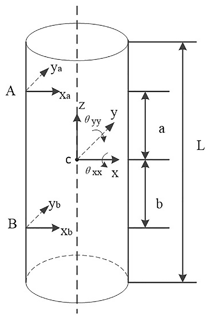
In this research, the radial four-DOF AMB system was explored for the vertical flywheel energy storage system. The rotor coordinate system c-xyz was established as shown in Figure 1.
Schematic diagram of radial MB rotor.
In Figure 1, m is the rotor mass; c is the geometrical center of the rotor; L is the total length of the rotor; A and B denote the two centers of the two-DOF radial AMB respectively; a and b are the distances from upper radial AMB and lower radial AMB to the rotor center point c; Jx, Jy, Jz are the moments of inertia of the rotor in the X–, Y–, and Z–axes; xa, xb,ya, yb are the radial displacements; θ xx and θ yy are the rotor angular. The relation between rotor centroid displacement xc, yc, θ xx , θ yy and other parameters is as follows:

The AMB rotor system is affected by gravity, electromagnetic force and unbalanced disturbing force. According to the electromagnetic force linearization equation, the relationship between the electromagnetic force, displacement and current can be expressed as


where, Fxaa, Fxbb, Fyaa, Fybb are the electromagnetic force; kia, kib and kxa, kxb, kya, kyb are current stiffness coefficient and displacement stiffness coefficient. According to (2), (3), (4), (5), one can obtain:

where I=[ixa ixb iya iyb]T,


On the other hand, due to impurities in material or processing technology, the mass is unevenly distributed. Then, mass imbalance is caused by the uneven mass distribution. Therefore, when the AMB rotor system worked at high speed, the geometric center line of the rotor will not coincide with the inertia axis, which will cause unbalanced disturbance. According to the rotor mechanics principle of AMB system, the disturbance can be described as:


where,
To sum up, according to the rotor dynamics theory, the equations of motion to radial four-degree-of-freedom rotor were established as follows:


Because the shaft core of the magnetic bearing is parallel to the maglev line in the vertical flywheel energy storage system, the gravity of the rotor was not taken into account. Combining equations (11) to (14), we have

where


Multiplying (15) with TL−1, we get

Let

Thus, the state-space model of the AMB rotor system with unbalance disturbance and gyro effect can be obtained
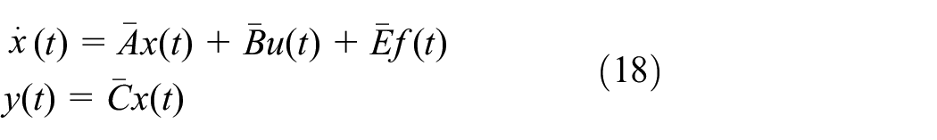
where,


Before the specific controller design, one lemma was introduced firstly.
(Ai) If
(Bi)
(Ci) ∃
Controller development
In order to effectively suppress the disturbance caused by mass unbalance and gyro effect in the AMB rotor system, an observer-based integral SM controller is constructed to ensure the accessibility of the sliding mode surface and the sliding mode motion of the state trajectory on the basis of the state-space equation (18) in Figure 2.

The block diagram of the AMB rotor system based on the proposed SM controller with state observer.
where
Sliding surface design
First of all, the integral sliding mode surface function is constructed as follows:

where

where
Calculating the derivative of equation (19) gives

In accordance with the equivalent control principle of SM control, when the controller is properly designed, the sliding mode function can reach onto the sliding surface
SM controller law design scheme
In this part, on the basis of the existing sliding mode surface function (19), appropriate rules used in SM control will be selected to ensure the stability of the AMB rotor system (18) under the action of the SM controller and meet the H∞ performance index γ.

where θ is a smaller positive number, and
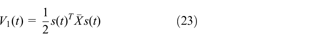
where
Considering the differential of (23) and

By substituting (22) into (24), we can get

In order to ensure

Through the norm calculation, the left side of (26) is scaled as follows:
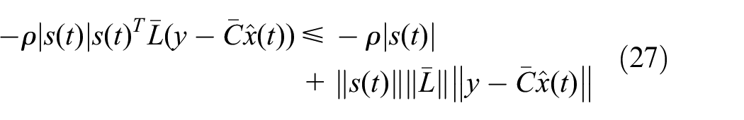
Considering
This completes the proof.
The above sliding mode surface function (19) has been proved to be reachable. Next, the main research is to stabilize the closed-loop AMB rotor system based on the controller (22).
In order to make the sliding mode function reach onto the sliding surface

Substituting (28) into (18), the state track can be obtained:

The observer error is defined as follows:

and

In the following, the sufficient conditions for the stability of the AMB rotor system satisfying the H∞ performance index γ are given. The controller gain K and observer gain L can be obtained by this condition.
Stability analysis


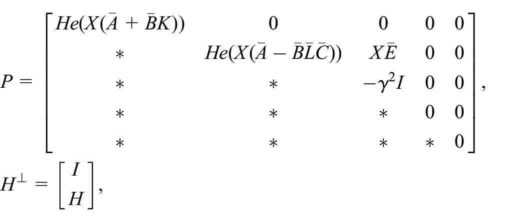
the AMB rotor system (18) will operate stably and meet the H∞ performance index γ with the controller (22).
Moreover, controller gain matrices K and

where X > 0
Then, the derivative of

To guarantee the asymptotic stability of the system (18) with H∞ performance, one needs

where


On the other hand,

where
Applying Lemma 1 to (38), we get

where

which is equivalent to condition in (32). So if the equation (39) holds, it can be ensure that
Modeling and simulation of control system
The effectiveness of the proposed observer-based SM control for the AMB rotor system will be verified in the following sections. The main parameters of the AMB rotor system using in the simulation process are shown in Table 1.
Simulation parameters of AMB rotor system.

During the simulation, it is assumed that x0 = [0 −0.05 0.05 0.03 0 0 0 0 ]
T
,


Substituting the above parameter K and state observer gain

The curve of sliding mode function.
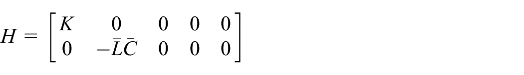
The curve of system input control.

The response curves of system states.
As can be seen from Figures 3 and 4, the chattering was effectively overcome by substituting
Under the same conditions, comparative simulation are also carried out for the AMB rotor system using the proposed sliding mode controller with state observer and the traditional sliding mode controller without state observer. The displacements of the upper magnetic levitation bearing A and the lower magnetic levitation bearing B in the x-axis and y-axis directions are presented in Figure 6.

Rotor position under the proposed SM controller with state observer and the traditional SM controller without state observer: (a) the response curve of state x1(t), (b) the response curve of state x2(t), (c) the response curve of state x3(t), and (d) the response curve of state x4(t).
Both the proposed SM controller with state observer and the traditional SM controller without state observer can make the rotor of the bearing quickly adjusted from the initial to the fixed position and remained stable in Figure 6. The speed response curves based on the proposed SM controller with state observer are faster and better than the conventional existing SM controller without state observer. As a result, the proposed SM controller has better dynamic characteristics than the traditional control strategy. Meanwhile, the number of decision variables involved in the proposed SM controller with state observer is 18.5n2 + (m + 5.5)n + 1, while the number of decision variables involved in the traditional SM controller without state observer is 11n2 + 12n.
Experiment platform and results
Establishment of experimental platform
In order to validate the effectiveness of the proposed new SM controller, the experimental platform of the flywheel energy storage system was established. The components of the flywheel energy storage system and its controller are shown in Figure 7. It is mainly consisted of the flywheel battery, flywheel battery control system, uninterrupted power supply (UPS), dissipation resistance box, Labview monitoring system, and vacuum pump.

Test platform for magnetic levitation flywheel energy storage system.
The flywheel battery system is the core component of the system. It is composed of flywheel, motor, magnetic suspension bearing and auxiliary bearing. The main function is to charge and discharge the flywheel battery.
The main task of flywheel battery control cabinet is to complete the start, stop and parameter setting of magnetic levitation bearing and motor.
The UPS can not only supply power to the flywheel energy storage system, but also ensure that the system will not be damaged due to external interference caused by sudden power failure.
The dissipative resistance box, taken as the load of the flywheel energy storage system, consumes the electric energy emitted by the flywheel battery. The Labview monitor computer is used to display the output displacement curves of the rotor. In order to ensure that the flywheel rotor is not subjected to air resistance during operation, vacuum pumps are used.
Experiment results
In this part, the proposed SM controller is utilized to guarantee the rotor displacement with the experimental platform in Figure 7. In this experiment platform, the mass of the flywheel AMB rotor systems is 58 kg, the external diameter and height are 318 and 815 mm. The stiffness of the AMB is 600 N/μm. Its charging and discharging times are 133.29 and 110.10 s, respectively. During the test, sampling frequency, nominal air gap, the barrier of the rotor displacement, and the rotor speed were set to 33.3 kHz, 0.5 mm, 0.25 mm, and 10,020 r/min.
The rotor trajectories used the proposed SM controller with state observer in this article and conventional SM controller without state observer are given Figures 8 and 9.

Axis position of static suspension MB with the proposed controller (a) the trajectory of the upper axis and (b) the trajectory of the lower axis.

Axis position of static suspension MB with the conventional SM controller (a) the trajectory of the upper axis and (b) the trajectory of the lower axis.
The voltage of the displacement sensor was transformed into the actual position of the rotor, and the experimental results of the two controllers were compared. As can be seen from Figures 8 and 9, all the axis positions changed within the range of 50 μm under the action of the SM controller. The designed SM controller with state observer could stabilize the AMB and was superior to the traditional sliding mode controller without state observer in terms of stability time and rotor position fluctuation, as shown in Table 2. In summary, it can be seen that the performances of rotor displacement orbits under the proposed controller was better than using conventional SM controller.
Comparison of experimental results.

In the meantime, the experimental results of the radial-axial output displacement of suspension AMB system applied the proposed controller are present in Figure 10 at 10,020 r/min. Figure 11 gives the corresponding control currents and other parameters.

The radial-axial displacement of MB at 10,020 r/min.

The parameters of flywheel battery control panel at 10,020 r/min.
From Figure 10, it can be observed that the peak-to-peak value in the rotor trajectory was controlled in the range of 120μm. It indicates that the performance with the proposed SM controller based on state observer is resultful. As can be seen from Figure 11, the energy stored by the flywheel energy storage system at this time is 27 W.H. The control currents 1, 2, 3, and 4 in x/y directions of the upper radial AMB are 2620, 2261, 2346, and 2529 mA. The control currents 5, 6, 7, and 8 in the x/y directions of the lower radial AMB are 2583, 2339, 2581, and 2309 mA. The control current 9 of the upper axial maglev bearing is 4378 mA, and the control current 10 of the lower axial maglev bearing is 3023 mA. Compared with static suspension, the radial control current of each degree of freedom in dynamic suspension increased, while the axial control current decreased. Due to the large mass of the flywheel rotor, the control currents of the axial AMB changes more than that of the radial AMB. In summary, the flywheel energy storage system realized the task of energy storage, and the static and dynamic suspension processes of the AMB are relatively stable. All of these demonstrate that the proposed method has significant effectiveness in the rotor imbalance vibration suppression.
Conclusion
In this article, an improved SM controller with the introduction of a state observer was presented for suppression of unbalanced disturbances in AMB rotor system. Firstly, the state-space model of a vertical radial AMB rotor system with unbalance disturbance and gyro effect is presented. Then, an observer based sliding mode function and switching surface were constructed. Unlike traditional observer structures, the gain L of the observer can be designed based on the parameters of the magnetic levitation bearing rotor system. Meanwhile, in order to provide sufficient conditions for the AMB rotor system in the form of linear matrix inequalities, a separation method based on Finsler lemma were proposed to eliminate the coupling among controller parameters and Lyapunov variables. Finally, simulation and experimental results are supplied to confirm the validity of the presented schemes. How to extend the proposed schemes for the AMB rotor systems with time-delay will be conducted in the future.
Footnotes
Handling Editor: Xiaodong Sun
Declaration of conflicting interests
The author(s) declared no potential conflicts of interest with respect to the research, authorship, and/or publication of this article.
Funding
The author(s) disclosed receipt of the following financial support for the research, authorship, and/or publication of this article: This work was supported in part by the Natural Science Foundation of the Anhui Higher Education Institutions (no. 2022AH051118, 2022AH051110, 2022AH051085), in part by the Research Initiation Fund of Chuzhou University (no. 2022qd45), in part by the Anhui Provincial Department of Education University Discipline (Major) Top Talent Academic Support Project (no.gxbjZD2020088).