
Abstract
This article presents a robust control method; all of the unknown disturbances and uncertainty values will be rejected. Suspension of active magnetic bearing system is aimed to figure out that the proposed control method is implementable for highly nonlinear unstable system. First, system state is described by dynamic model, with unknown lump of uncertainty value. Subsequently, the cascade control with inner and outer loops is defined by sliding mode control based on disturbance and uncertainty estimator. The outer control loop is used to force the system state converge on the predefined surface, while inner control loop is used to control the current of electrical part of the system. Finally, the simulation results show that the proposed control method is good at tracking trajectory.
Introduction
Due to non-contact and frictionless nature, the magnetic suspension of active magnetic bearing (AMB) offers many kinds of machines, potentially promising sub-system devices, such as turbine engines, helicopter, and flywheel energy, and vacuum pump was introduced in previous works.1–3 Usually, the desired goal is the rotor can track precise predefined positions, there is non-contact between stator and rotor. Chen and Lin 1 presented non-singular sliding mode control for one axial suspension of AMB system. Su et al. 4 presented the combination of fuzzy logic control with conventional sliding mode control for almost the same system with Chen et al. Our system is the same with Su et al. 4 Due to the tracking predefined orbit for highly nonlinear system, many studies implemented advanced control methods, such as Lin et al., 3 Chen and Lin, 1 or Su et al. 4 under high nonlinear mode, and the external disturbances are unknown or very expensive to estimate. Tsai et al. 5 presented robust observer-based optimal control method; therein system state and disturbance are equipped by observers. Those papers ignored that AMB system can be controlled by electrical values. Otherwise, the AMB is highly unstable system, the external disturbances and the uncertainty values are unknown, estimated term of these is need to know. Due to these approaches, Do et al. 6 presented disturbance observer-based fuzzy sliding mode controller (SMC) method, and Liu et al. 7 employed nonlinear disturbance observer-based backstepping sliding mode control. All of them proved effective results of the observer to estimate the unknown disturbances. This study proposes the disturbances and uncertainty estimator to adverse the unexpected values. All unknown disturbances and lump of uncertainty are bounded. Otherwise, the proposed method is implementable with both of matched and mismatched disturbance systems. The lump of uncertainty is bounded, and this value will be approximated by a filter gain, herein the filter is named low pass filter. Some of the exogenous disturbances might challenge the system at sudden time periods.
In other words, the suspension of AMB system is highly unstable, and then this study describes system state by dynamic model. The mismatched disturbances and uncertainties estimator are offered first. Subsequently, robust controller named cascade controller based on disturbance and uncertainty estimator (DUE) is presented. The inner loop used SMC to force the electrical variable converge on predefined state, and outer loop used SMC to force the mechanical part converge on the predefined surface. In order to take advantage of SMC, Petit et al. 8 used backstepping sliding mode control for stiffness robot and achieved desired goal for tracking trajectory. Taheri et al. 9 employed a backstepping SMC for pneumatic cylinders.
This article is organized as follows. The “Mathematical modeling of AMB system” section describes mathematical equations of suspension of AMB system and problem statement. The “DUE-based control laws” section presents the design of disturbances and uncertainty estimator-based controller. “An illustrative example” section shows simulation results and some discussions. The conclusion will be given in the “Conclusion” section.
Mathematical modeling of AMB system
Due to non-contact characteristic between rotor and stator, the upper and lower electromagnet coils are supplied by the current to generate electromagnetic force for keeping the rotor at the expected position. This study considered the case of the thrust disk is embedded on the rotor of the AMB system. The distances of the thrust disk and stator are determined by the air gaps

Geometry differential coils for linearization of the force-current characteristics.
Then, the system model is presented as

where m is mass of the rotor;
The system state can be written as

Denote

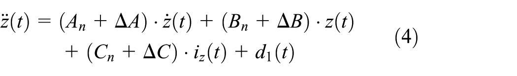
Then, equation (2) can be written as

The uncertainty values are unknown and can be estimated by

where

Now, redefine the above compact form as dynamic equation

where the system state
All explanations of above equations just show the system state using mechanical part. Under requirements of cascade control, system’s electrical state is required to reveal. The Faraday’s law indicates that the amplifier output voltage is surrounded by

where
Refer

where
DUE-based control laws
The dynamic system without knowing the lump of uncertainty is presented in equations (4), (6), and (8); the main problem of this term is how the controller can track the precise predefined trajectory. The DUE-based cascade position-current control will be constructed. Otherwise,10,11 Were applied flux-control, current-control. This study proposes SMCs for both inner and outer loops. The above-proposed method is improved by low pass filter; this filter is used for estimating the lump of uncertainty. Basically, sliding mode control is robust control method; it can be applied for many kinds of systems, such as nonlinear or linear.12,13,14 Each system state will be forced to converge on the prespecified surfaces. The AMB system controlling expects that the rotor can track the trajectory precisely. Many unknown external disturbances will be tested on the system. The cascade controller is applied to achieve the desired goal. In order to track trajectory more precisely, the lump uncertainty of inner loop and outer is bounded and estimated by a filter.
Position control design
Due to the non-contact characteristic of the rotor and stator, the desired goal is to keep the rotor and stator by air gaps at every given time. This section presents SMC for AMB system. First, SMC concept will be discussed with simple surface as

Sliding mode surface is selected as

where xr, xm are the reference signal, and the measured signal of the distance between the stator and the thrust disk of the system;

Combining equation (4) and equation (9), the current is calculated as

where Iout is reference signal of inner loop. In order to archive the highly precision tracking control and low chattering value, the
Design saturation function
Sliding mode control usually produces chattering by switching part. This proposed method replaced signum function by saturation function; the function is presented as


Then, equation (11) can be written as

Current control design
Usually, control electrical part is more effective than mechanical part; the SMC for inner loop is proposed as15,16

Combine with equation (8), we have

To achieve the desired goal
DUE concept
First, basically concepts of DUE will be given. Every dynamic system is unable to know disturbances and uncertainty values; then estimator design is required. Taloe and colleagues17,18 and Ren et al. 19 implemented the DUE-based control for those system and get perfect performances. This study also equips the DUE-based controller as follows.
DUE-based inner control loop
This system is presented as two parts. First, mechanical part under desired prespecified position expects to achieve, and the inner electrical part with expected more precipice tracking error. There are many unknown and unexpected exogenous disturbance values in sudden time period. With chosen input voltage as

Refer

otherwise

or

The lump of uncertainty can be observed by a filter. Suggesting strictly proper low pass filter as

where

Combination of equation (15) and equation (20) leads to

Choose
DUE-based outer control loop
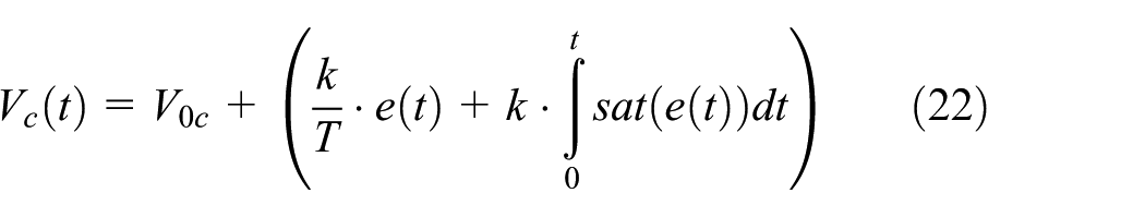
The original controller is designed as equation (11), then apply the low pass filter with inverse of Laplace function; the control signal is presented as

or
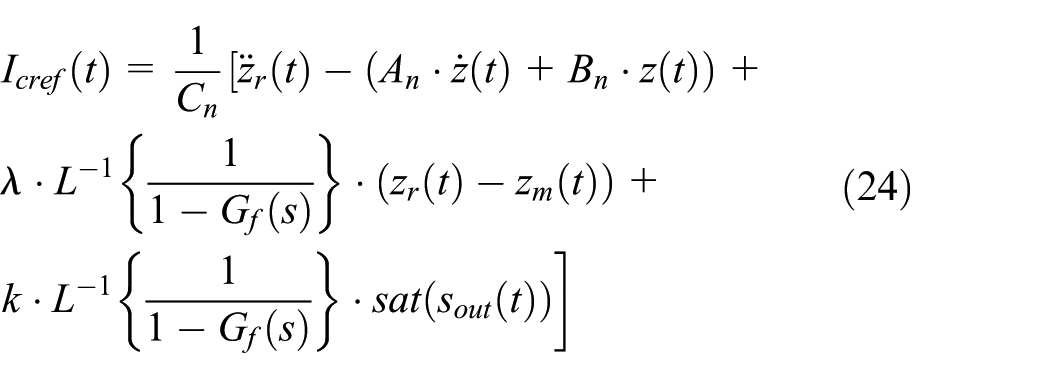
Equation (24) can be simplified as

At this time, the unknown disturbances and uncertainty are rejected by the two DUE-based cascaded position-current control.
Stability analysis and performance
(a) Stability analysis
The estimation errors of the lump uncertainty are determined as

where
The filter track error terms in equation (9) can rewritten as

or

where

Solving equation (27) and equation (28) yields

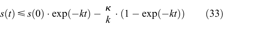
Otherwise, the lump of uncertainty of the outer loop is bounded as

then

Combining equation (32) and equation (30) yields
Substituting equation (34) into equation (30) yields

Refer


(b) Performance
The combination of the equations (26-29) will lead to

or

Substituting equation (38) to equation (29) yields

Combination of lump uncertainty in equation (31) is bounded. The low pass filter was chosen above will effect to tracking error value as

We chose
Following the above analysis, the results for each method will be given in the next section as step 1—the performance of cascade controller will be appeared—and step 2—disturbance and uncertainty-based controller for outer loop will be given. Finally, the DUE is designed for cascaded position-current controller (see Figure 2).
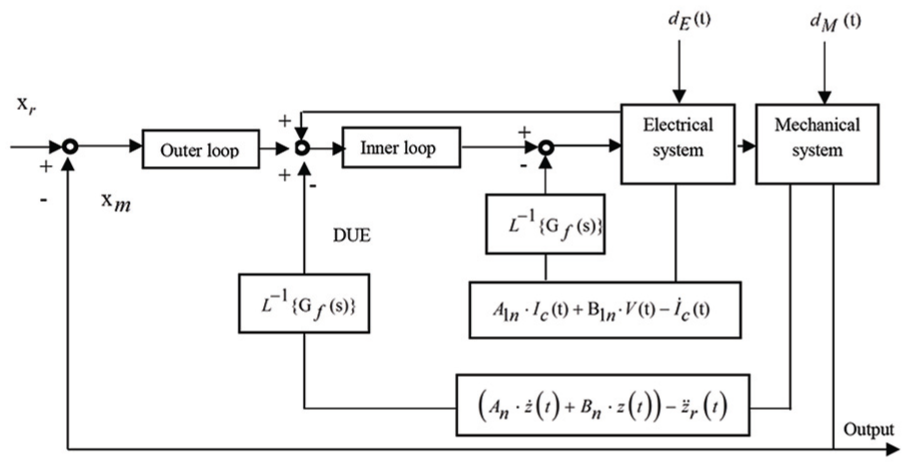
DUE-based cascaded position-current controller.
An illustrative example
Corresponding to the proposed structure mentioned above, the simulation results are given in this section. These procedures present the cascade controller for dynamic system; the system state will be converged to prespecified position by forcing on mechanical and electrical parts. The requirements of designing filter for this problem are satisfied strictly by proper stable filters.
Those results demonstrate the effects of the proposed method on the AMB system.
Step 1: Cascade control method-based system modeling
The results of this part are given by the tracking error value equal to
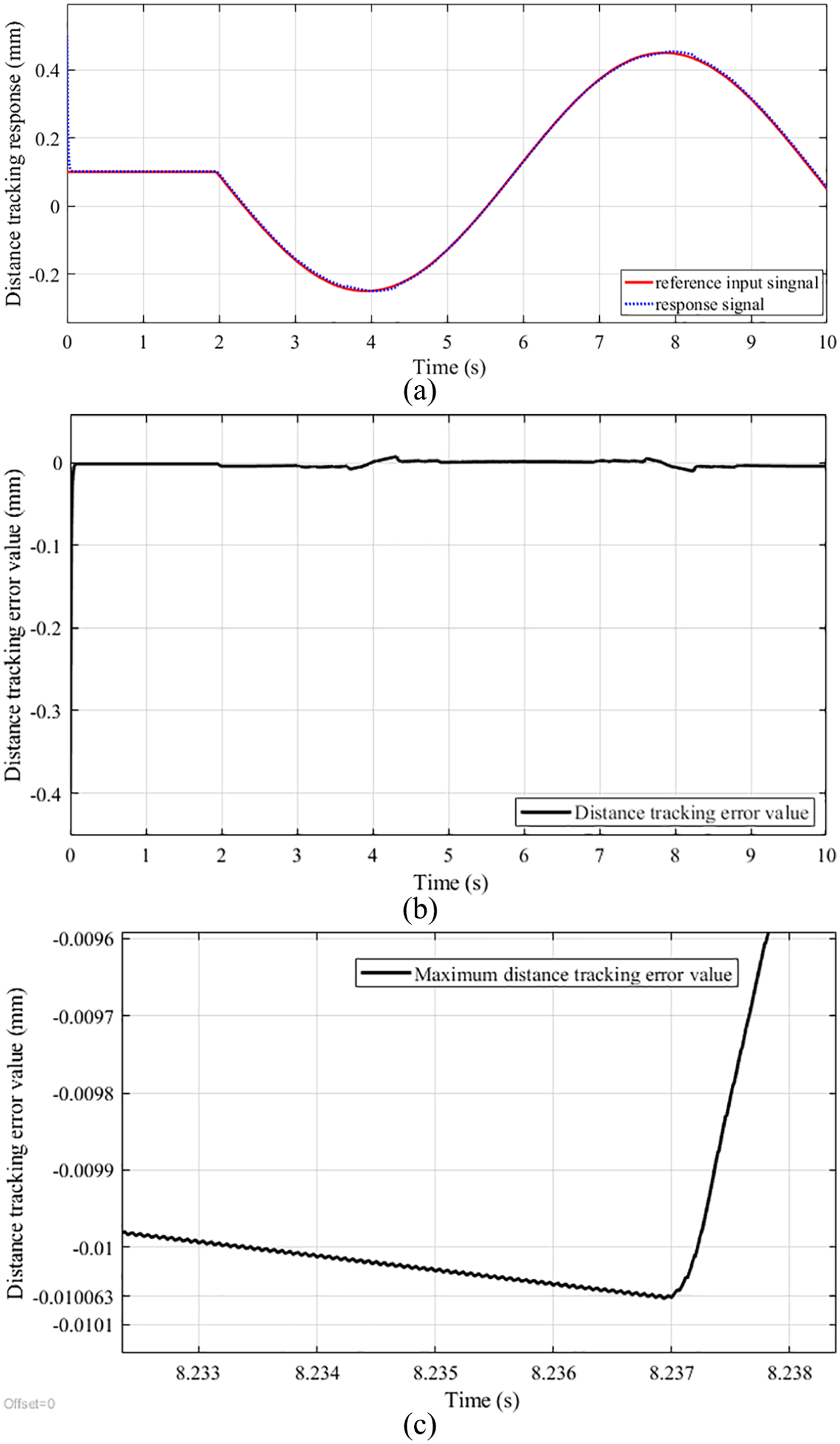
Cascade controller tracking values: (a) response tracking, (b) distance tracking error, and (c) maximum distance tracking error value.
The distance tracking error value performs that the proposed scheme is applicable for dynamic system.
Step 2: DUE design for outer loop
Under sliding mode and designed
Step 3: DUE design for cascaded position-current controller
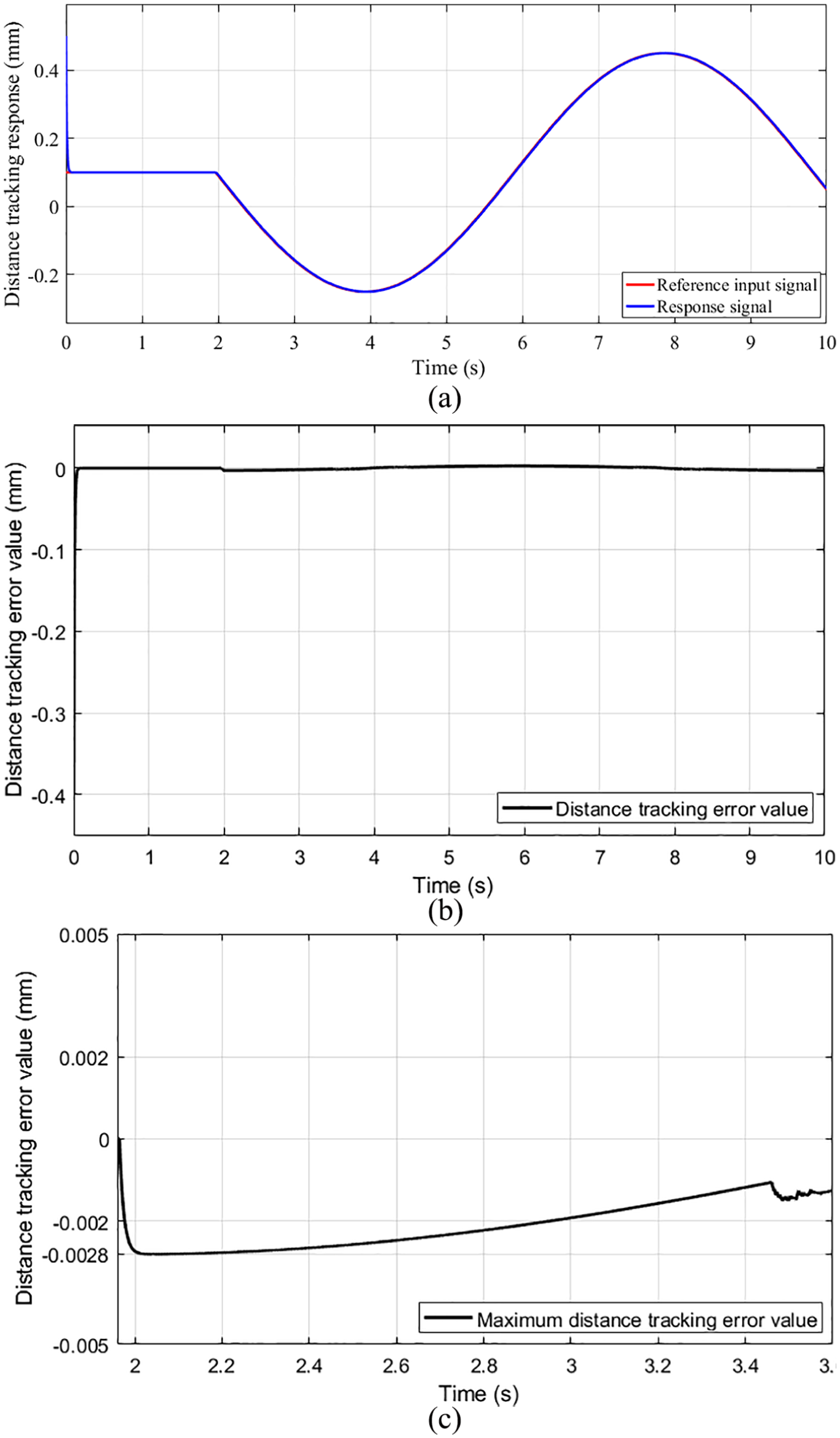
Inner DUE-based cascaded position-current control distance tracking: (a) distance response, (b) distance tracking error, and (c) maximum distance tracking error value.
This procedure ensures that the proposed control method is quite good at tracking trajectory. The distance tracking error is much small than above procedures. The average value of the distance tracking error is equal to
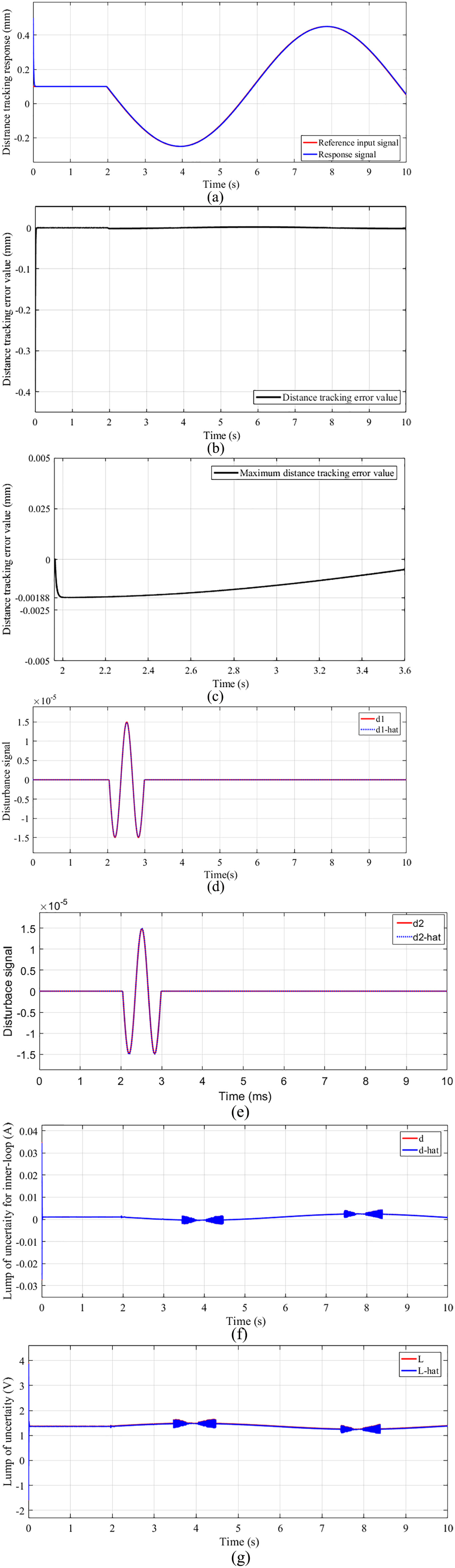
DUE-based cascaded position-current controller: (a) distance tracking response, (b) distance tracking error, (c) maximum distance tracking error value, (d) inner loop disturbance estimation response, (e) outer loop disturbance estimation response, (f) inner lump of uncertainty estimation response, and (g) outer loop disturbance estimation response.
The test results show that the adaptation of the proposed controller and the transient response are quite fast. Moreover, the distance tracking error is a satisfied desired goal. For future work, we will apply this method to real system, in which the mechanical structure is the same with Chen and Lin. 1
Conclusion
With a design methodology for dynamic equation with many unexpected disturbances and unmeasurable uncertainty values, the estimator-based cascade controller is given in this article. In order to achieve the prespecified goals, the cascade sliding mode, disturbances, and uncertainty estimator are applied. The perfection of the performed results points out the dynamic system with unmeasurable disturbances, and uncertainties can be estimated through the terms of sliding surface or tracking error. This article demonstrates the only results at scenario of thrust disk embedded on the rotor of the system. The proposed methodology is good at tracking with time-varying trajectory.
Footnotes
Appendix 1
The mechanical parameters of the suspension active magnetic bearing system is referenced from Chen et al. 1 , these values are given in Tables 1–4; otherwise, the electrical value for future implementation is tested—some parameters like coil inductance and resistances are chosen to apply for this AMB system. The controller parameters will be revealed in this section; all the parameters were chosen to satisfy the stable condition above.
Handling Editor: Yunn-Lin Hwang
Declaration of conflicting interests
The author(s) declared no potential conflicts of interest with respect to the research, authorship, and/or publication of this article.
Funding
The author(s) received no financial support for the research, authorship, and/or publication of this article.