
Abstract
Traditional finite control set model predictive control (FCS-MPC) selects an optimal voltage vector in one control cycle. However, considering multiple control cycles, it cannot be proved that the voltage vector is optimal, and the uncertainty of PMSM parameters seriously affects the prediction accuracy. In order to balance the relationship between switching frequency, steady-state performance, and robustness, a multi-step robust FCS-MPC is proposed. Firstly, an incremental prediction model is established to eliminate the flux linkage of permanent magnets. The inductance parameters in the incremental model are identified online based on the observer and inductance extraction algorithm. Then, based on the principle of no-beat, the candidate voltage vector in two control periods is simplified to get the candidate voltage vector, and the cost function is used to determine the optimal voltage vector again. Finally, the proposed FCS-MPC method is compared with the traditional FCS-MPC method. The experimental results show the effectiveness of FCS-MPC strategy.
Keywords
Introduction
With the rapid development of industry, society is facing serious problems such as energy shortage and environmental pollution. Therefore, it is very necessary to develop new clean energy. Many countries and regions focus on wind power generation, new energy vehicles, and other aspects.1–6 As the core component of the above system, the motor has been widely studied, among which, the permanent magnet synchronous motor stands out in a crowd of motors because of its high-power density, high efficiency, lightweight, and other advantages.7–11
The control algorithm directly affects the performance of the PMSMs system. The traditional schemes such as magnetic field-oriented control (FOC) and direct torque control (DTC) have the disadvantages of insufficient dynamic performance and poor steady-state performance respectively.12–17 In recent years, model predictive control (MPC) has been regarded as a powerful alternative to FOC because of its simple principle, easy of dealing with multiple constraints, and fast dynamic response.18–21 According to different control variables, MPC can be divided into predictive current control,22–24 predictive torque control,25,26 and predictive speed control,27,28 among which predictive current control is widely used because there is no adjustment of the weighting factor. According to whether the modulation scheme is adopted or not, MPC can be divided into finite control set model predictive control (FCS-MPC)29,30 and continuous control set model predictive control (CCS-MPC), 31 wherein FCS-MPC can calculate the optimal voltage vector by minimizing the cost function and directly act on the inverter, and it is easy to add constraints, which is more concise. 32
Conventional FCS-MPC outputs only one voltage vector in one control cycle, which inevitably leads to a large error between the expected voltage and the output voltage and deteriorates the steady-state performance. To solve this problem, a multi-vector scheme is proposed. 33 The basic principle of the multi-vector scheme is to improve the steady-state performance of the system by outputting multiple voltage vectors in one control period. Duty cycle control is used in Sun et al., 34 zero vector and non-zero voltage vector are output in a control period so that the amplitude of the output voltage is adjusted. In Gonçalves et al., 35 the output voltage amplitude is adjusted by constructing a virtual voltage vector. In Sun et al., 36 duty cycle control and virtual vector are integrated to adjust the amplitude and phase of the output voltage simultaneously. In addition, two-vector MPC and three-vector MPC exist,37–39 and the reference modulation scheme greatly increases the flexibility of the output voltage. However, the above scheme undoubtedly increases the average switching frequency of the system because of the output of multiple voltage vectors in one control cycle.
To balance the relationship between the steady-state performance of FCS-MPC and the switching frequency, a multi-step FCS-MPC is introduced. The multi-step FCS-MPC can reduce the switching frequency and improve the steady-state performance by considering the optimization of multiple control cycles and adding switching limits to the cost function.40–42 However, the set of alternative voltage vectors that need to be computed iteratively for multi-step FCS-MPC increases exponentially with the increase in step size. Aiming at the heavy computation burden, many scholars reduce the computation amount by using a spherical decoding algorithm or gradient descent scheme.43,44 A simple two-step scheme is proposed in Zhang et al. 45 The series structure is used to first reduce the alternative voltage vector set and then the cost function is used to calculate the optimal voltage vector, which reduces the switching frequency and improves the steady-state performance. However, another problem with FCS-MPC is that it has a strong parameter dependence. The prediction accuracy will decrease with parameter mismatch.
At present, many scholars have studied the robustness of model prediction, which can be divided into observer-based estimation compensation, online parameter identification, and model-free scheme.30,46 The principle of an observer-based estimation compensation scheme is to estimate and compensate the disturbance caused by parameter mismatch as a whole to the reference voltage. In Sun et al., 47 a sliding mode observer is used to estimate the lumped disturbance compensation to the reference voltage, and a robust dead-beat predictive control is realized. Li et al. 48 applies the observer to FCS-MPC, and the estimated disturbance compensation to the reference voltage is used to determine the optimal voltage vector. At the same time, the virtual voltage vector is added to improve the accuracy of the voltage output, effectively reducing the parameter sensitivity of FCS-MPC. Another efficient scheme is to estimate time-varying parameters online and apply them to the prediction model. Traditional identification schemes include recursive least square (RLS) method, extended Kalman filter (EKF), and model reference adaptive (MRA) method.49–53 RLS requires a lot of computing and storage space. The problem of adaptive rule design is complicated in MRA. EKF has a lot of matrix operations and it is also very complex to identify multiple parameters. The advantage of a model-free scheme is that it does not use motor parameters to avoid the impact of parameter mismatch, which has attracted the attention and research of many scholars. Model-free schemes include the use of multiple sampling current differences to predict future currents, 54 or the design of a hyperlocal model using a first-order hyperlocal model instead of the PMSM model.55,56 In addition, the model-free scheme also includes a data-driven approach to design the controller directly through input and output, 57 but there are problems such as a large amount of required data, difficult data processing, and a large computational burden.
Therefore, a robust two-step FCS-MPC is proposed. The incremental prediction model is constructed to eliminate the flux linkage of the permanent magnet and reduce the voltage vector backup set by the principle of no beat and voltage vector non-switching. Inductance parameters in the incremental prediction model are identified online by designing an observer and an inductance extraction algorithm. Finally, the optimal voltage vector is obtained by substituting the reduced voltage vector set into the cost function.
The rest of this article is organized as follows. Section “Conventional FCS-MPC of PMSMs” describes the model of permanent magnet synchronous motors and the traditional FCS-MPC. Section “Simplified robust two-step FCS-MPC” introduces the simplified two-step robust FCS-MPC. Section “Experimental result” shows a comparison of the proposed scheme with conventional FCS-MPC. Conclusions and future outlook are presented in Section “Conclusion” and Section “Future outlook,” respectively.
Conventional FCS-MPC of PMSMs
Mathematical model of the PMSMs
In this paper, surface-mounted PMSMs (SPMSMs) are used, and their inductance meets Ld = Lq = L. Therefore, the voltage equation of SPMSMs in the rotating coordinate system (d−q coordinate system) is expressed as:

where
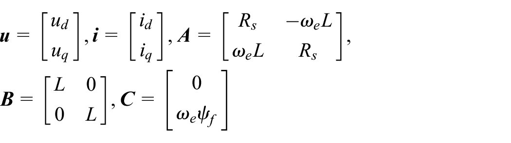
ud(q), id(q) represent the voltage component and the current component of the d−q axis respectively, and ωe is the electric angular velocity. Rs and ψf and represent stator resistance and flux linkage.
The electromagnetic torque equation of the SPMSMs is given by

where Pn represents the number of pole pairs of SPMSMs.
Conventional FCS-MPC strategy
According to Euler’s discrete equation, (1) can be expressed as:

where

Tc is the control period, k and k + 1 represent the current moment and the next moment, respectively.
The eight basic voltage vectors of the two-level voltage source inverter (2L-VSI) shown in Figure 1 are substituted into (3), and the result of the predicted current is compared with the reference value. By minimizing the current tracking error, the following cost function is established:

where the superscript “ref” represents the reference value. The reference value of id is 0, and the reference value of iq is output by the PI controller of the speed loop. The block diagram of conventional FCS-MPC is shown in Figure 2.
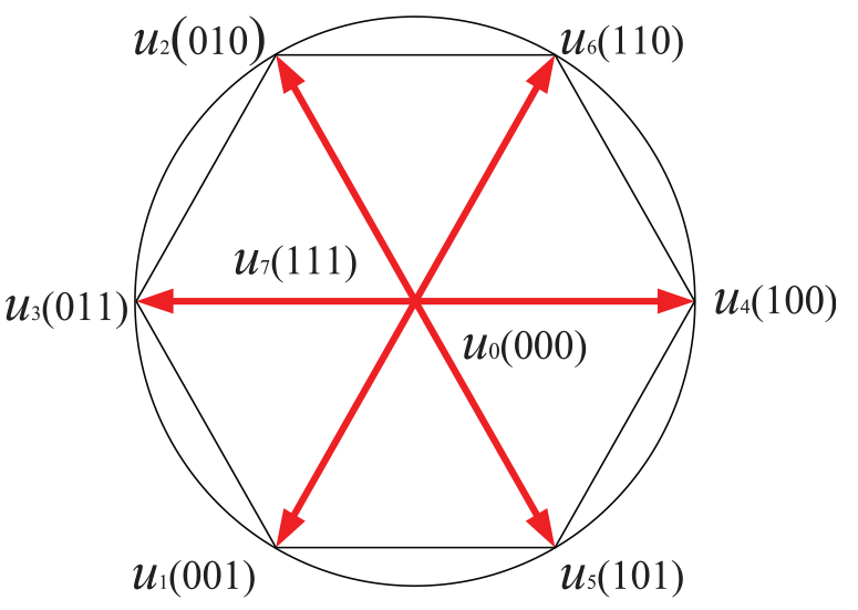
The basic voltage vectors of 2L-VSI.

Block diagram of conventional FCS-MPC.
Based on the above analysis, the traditional FCS-MPC only outputs one voltage vector in one control cycle, resulting in poor steady-state performance. An effective solution to this problem is multi-vector MPC. The application performance of a multi-vector scheme in FCS-MPC is given in Li et al., 30 and its performance is shown in Figure 3. It can be observed that the current THD and torque ripple of the system decreases with the increase of the vector output, but the calculation time of the scheme is undoubtedly further extended. In addition, as the switching of voltage vectors becomes faster, the average switching frequency of the system undoubtedly increases.

Performance comparison of multi-vector schemes in Li et al. 30
Simplified robust two-step FCS-MPC
The control block diagram of the simplified two-step robust FCS-MPC strategy proposed in this paper is shown in Figure 4, which mainly includes step1 and step2: reference voltage calculation and candidate voltage vector set determination based on the deadbeat principle, incremental prediction model, cost function, and inductance extraction algorithm.

Block diagram of the simplified two-step robust FCS-MPC.
Incremental prediction model
According to (3), the accuracy of the prediction model depends on the accuracy of the motor parameters. To reduce the sensitivity of parameters, an incremental prediction model was established to eliminate the influence of permanent magnet flux on the prediction formula. The specific steps are as follows:
First, a backward Euler expansion of (1) is performed to obtain:

Then, subtract (5) from (3) to obtain the incremental prediction current model:

where

Due to the calculation delay, the current prediction model obtained by one-step delay compensation for model (6) is as follows:

If traditional iterative calculation is used, eight calculations are required to determine the optimal voltage vector. To reduce the computational burden, based on the deadbeat principle, the predicted current id(k + 2) and iq(k + 2) should reach their reference values by the end of the next control cycle. Therefore,

Simplified two-step MPC
Unlike traditional FCS-MPC, which only considers the current tracking within one control period and determines an optimal voltage vector after obtaining the reference voltage, the prediction range is extended to two steps. When the optimal voltage vectors of two adjacent control cycles are the same, the switching state of the inverter remains unchanged, that is, the switching change is suppressed. Therefore, to balance switching frequency and steady-state performance, the selection of the optimal voltage vector is extended to two control cycles.
Therefore, the proposed voltage vector optimization scheme is as follows: First, after the reference voltage is obtained, it is converted to the reference voltage in the rest coordinate system according to the change of coordinates. Then, according to the reference voltage, the backup set of the optimal voltage vector is determined in the voltage vector space as shown in Figure 5. The relationship between sectors and alternative voltage vector sets is shown in Table 1. Each sector contains one zero vector and two non-zero vectors, and through the principle of no beat, the calculation is reduced from eight times to one time, which effectively reduces the calculation burden. It is worth noting that different from the traditional reference voltage calculation scheme based on the principle of no beat, the reference voltage scheme in this paper can not directly determine the optimal voltage vector, and it is only used for the preselection of the optimal voltage vector within two control cycles.
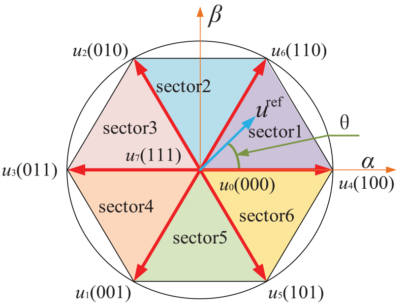
Voltage positioning method based on deadbeat principle.
Relation between sectors and alternative voltage vector sets.

After the alternative voltage vector set is obtained, the second step is to select the optimal voltage vector from the three candidate voltage vectors. The optimal voltage vector backup set is the set of optimal and suboptimal voltage vectors at the k + 2 moment. The principle of the series structure proposed is to evaluate the alternative voltage vector set at k + 2 moment by current tracing at k + 3 moment. Therefore, the scheme can be understood as the selection of the optimal set of voltage vectors within two steps.
The method of selecting the optimal voltage vector set at k + 2 moment is introduced in (8). The predicted current increment model at k + 3 moment is expressed as follows:

Then, taking sector 1 as an example, the corresponding cost function based on the current tracking error is designed. Select three candidate voltage vectors from the k + 2 moment and plug them into (9) to obtain the optimal voltage vector output to the inverter.

2L-VSl has two voltage vectors of zero amplitude, to reduce the average switching frequency of the system. The rules for applying the two zero vectors are as follows: If the optimal output at the previous time is u4 (whose switching signal is Sa = 1, Sb = 0, Sc = 0), then u0 (whose switching signal is Sa = 0, Sb = 0, Sc = 0) is used instead of u7 (whose switching signal is Sa = 1, Sb = 1, Sc = 1). If the optimal output voltage vector at the previous time is u6 (whose switching signal is Sa = 1, Sb = 1, Sc = 1), then u7 is used (whose switching signal is Sa = 1, Sb = 1, Sc = 1).
Inductance extraction algorithm
The incremental prediction model shown in (7) eliminates the influence of permanent magnet flux linkage, but inductance and resistance parameters still exist, and the influence caused by the mismatch of resistance parameters is small and can be ignored. 58 Therefore, an inductance extraction algorithm is designed to enhance the robustness of the SPMSMs drive system.
Since the d-axis inductance and the q-axis inductance are equal, taking the d-axis as an example, the voltage equation considering parameter uncertainty is expressed as:

The perturbation term is estimated by designing an observer:
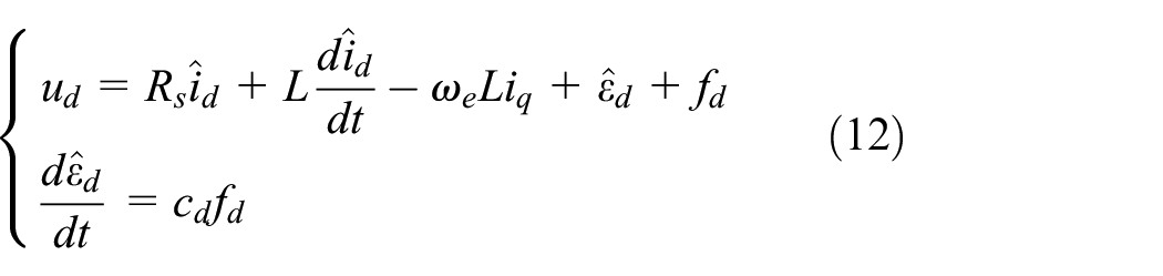
where “^” represents the estimated value. fd is the control function, cd is a positive sliding mode parameter.
Subtract (11) from (12) to obtain the estimated error term:

where
The sliding mode function adopts variable gain approximation law to reduce tremor, expressed as:
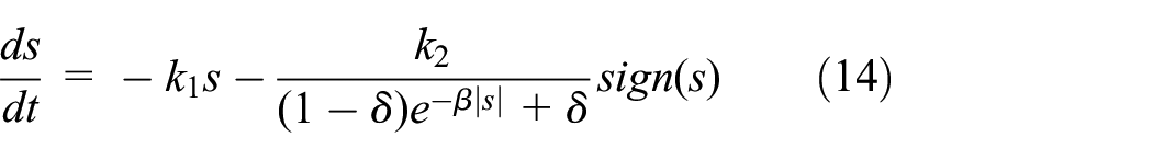
The stability analysis of the designed sliding mode observer is as follows:

When the parameters k1 > 0, k2 > 0, β > 1, and 0 < δ < 1 are set, the reaching law satisfies the stability condition, which means that the system is stable.
Taking e2 as the disturbance of the control function, design the following sliding mode control function as follows:

Substitute (16) into (12) and e1 is considered equal to zero at steady state, so it can be simplified to:

where
According to (16), the estimated inductance can be derived as:

The inductance extraction algorithm is shown in Figure 6, where kp and ki are the proportional and integral gains of the PI controller. The transfer function is expressed in the form of a typical type II system:

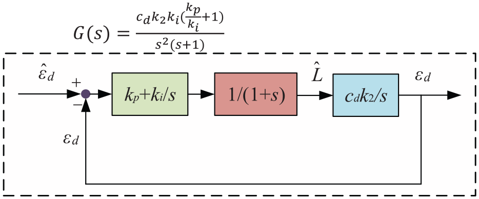
The inductance extraction algorithm.
Experimental result
Figure 7 shows the construction of the experimental device, and the relevant SPMSM parameters are shown in Table 2. To verify the advantages of the scheme in steady-state performance, switching frequency, and robustness, the proposed scheme is compared with conventional FCS-MPC. Rtunit’s real-time controller RTU-BOX 201 was adopted in the experiment, which integrated ADC, PWM, position signal input, and high-quality communication interface modules, and the experimental sampling frequency was set at 10 kHz. The controller block diagram based on the experiment of the proposed scheme is shown in Figure 8.

The experiment platform.
SPMSM system parameters.


Controller block diagram based on RTU BOX.
Steady-state performance and switching frequency comparison under normal parameters
First, to demonstrate that a simplified two-step FCS-MPC can effectively trade off the relationship between switching frequency and steady-state performance. The steady-state performance and switching frequency of conventional FCS-MPC and simplified two-step FCS-MPC are compared under normal parameters. First, the control frequency of both schemes is set to 20 kHz. Set the load torque to 8 Nm and the speed to 2000 rpm. Figure 9 shows the speed, phase current, and corresponding harmonic analysis of the two schemes. It can be seen from Figure 9 that both schemes can track the reference speed well, with the THD of the traditional scheme being 5.51% and that of the proposed scheme being 7.26%. To illustrate the universality of the scheme, the THD of the two schemes was compared under the same load but at different speeds, such as 500, 1000, and 1500 rpm, as shown in Figure 10. Figure 10 illustrates that the steady-state performance of conventional FCS-MPC is slightly better than that of the proposed two-step FCS-MPC. However, this is shown at different switching frequencies. At the same time, the switching frequency of the two schemes is shown in Figure 11, and it can be observed that the switching frequency of the proposed scheme is always lower than that of the traditional FCS-MPC.

Comparison of speed, A-phase current, and THD: (a) conventional FCS-MPC and (b) the proposed FCS-MPC.

Comparison of THD with different motor speeds.

Comparison of switching frequency with different motor speeds.
To show the superiority of the proposed scheme, the THD of the traditional FCS-MPC and the proposed scheme are compared by maintaining the same switching frequency at the same speed of 2000 rpm and load of 8 Nm. To prove its universality, it was verified at different rotational speeds, as shown in Figures 12 and 13. According to the data in Figures 12 and 13, it can be seen that the proposed scheme has smaller THD and better steady-state performance under the same switching frequency and experimental conditions. Therefore, the proposed two-step FCS-MPC can effectively balance the relationship between steady-state performance and switching frequency.

THD of traditional FCS-MPC at 2000 rpm, 8 Nm load, and 2.31 kHz switching frequency.

THD comparison of two schemes at the same switching frequency and different speeds.
In addition, to further prove the effectiveness of the proposed scheme. The proposed scheme is compared with the two-step FCS-MPC proposed in Zhang et al., 59 which applies the same voltage vector in both control cycles. The motor speed is set at 1000 rpm and the load is set at 10 Nm. Figure 14 shows the speed and current THD of the two schemes.

Speed and THD comparison of the proposed FCS-MPC and FCS-MPC in Zhang et al. 59
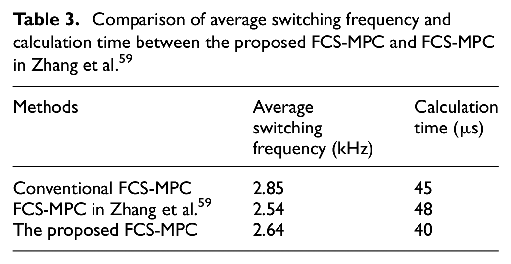
It can be observed that the THD of the proposed scheme is smaller, and the THD of the two is 5.98% and 4.66% respectively, because the vector is not restricted in the two control cycles of the proposed scheme, while the FCS-MPC in Zhang et al. 59 considers the vector invariant in the two control cycles. Table 3 shows the calculation time and the average switching frequency of the system for the above two schemes and the traditional FCS-MPC. Because the switches in the two control cycles are forcibly restricted, the average switching frequency in Zhang et al. 59 is smaller, but the calculation time is relatively maximum. The calculation burden is large because 11 enumerations are required in Zhang et al., 59 including eight enumerations for the first time for the preselection of three voltage vectors and three enumerations for the second time for the selection of the optimal value. The scheme proposed in this paper requires three enumerations, while the traditional FCS-MPC requires eight enumerations.
Comparison of average switching frequency and calculation time between the proposed FCS-MPC and FCS-MPC in Zhang et al. 59
Robust performance comparison
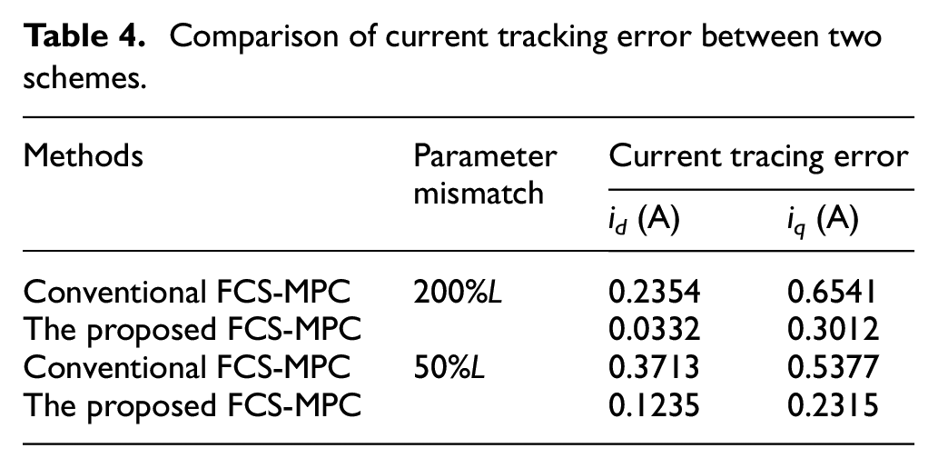
The parameters of the sliding mode observer and inductance extraction algorithm are set continuously as follows: k1 = 800, k2 = 800, β = 2, δ = 0.3, kp = 0.04, ki = 0.03. To show the suppression of parameter sensitivity by the proposed incremental prediction model and inductance algorithm, the conventional FCS-MPC is compared with the proposed two-step FCS-MPC. Because the inductance parameters of the motor cannot be changed quantitatively in real time, this paper simulates the disturbance under the change of parameters by changing the inductance parameters in the controller. First, because the variable φf is not used in the incremental prediction model, it will not be affected by its parameter mismatch. At 0.7 s, the load torque is set to rise from 5 to 8 Nm, and the speed is set to 1500 rpm. Figures 15 and 16 show the stator current tracking effects of the two schemes under 200% and 50% inductance respectively. The red realization represents the reference value of the current, and the dashed line represents the time point at which the inductance changes. It can be seen from Figures 15 to 16 that traditional FCS-MPC has large tracking errors when inductance parameters are mismatched, while the proposed robust two-step FCS-MPC has good current tracking performance. To further explain the superiority of the current tracking performance of the proposed scheme, the tracking errors of both are shown in Table 4. It can be seen from Table 4 that when the parameters are mismatched, the tracking error of the proposed scheme is small, no matter the d-axis current or the q-axis current. Therefore, the experimental results demonstrate the robustness of the proposed scheme.

Comparison of current tracking performance at 200%L: (a) conventional FCS-MPC and (b) the proposed FCS-MPC.
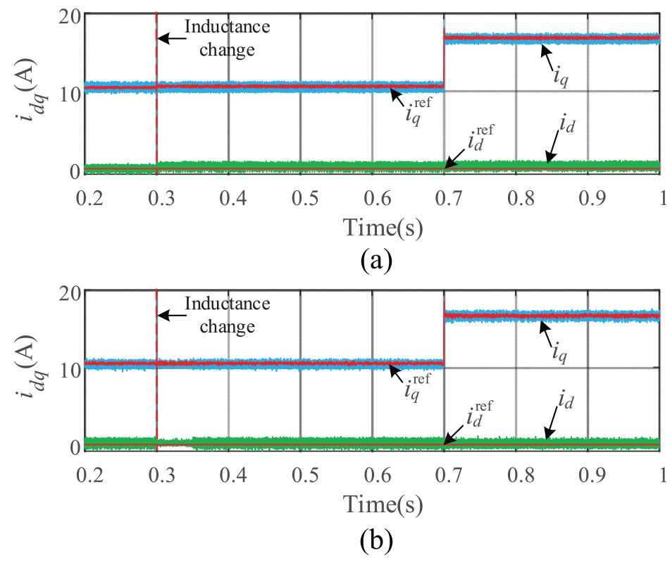
Comparison of current tracking performance at 50%L: (a) conventional FCS-MPC and (b) the proposed FCS-MPC.
Comparison of current tracking error between two schemes.
Conclusion
In this paper, a simplified robust two-step FCS-MPC is proposed, which extends the optimization of traditional FCS-MPC from one step to two control cycles. In this study, an incremental prediction model is established to eliminate the influence of permanent magnet flux linkage. On this basis, the reference voltage is calculated using the principle of deadbeat control, and three alternative voltage vectors are determined by the principle of non-switching voltage vectors within two steps. After obtaining the alternative vector set, the optimal voltage vector is calculated by using the cost function of the series structure, and the output is applied, which greatly reduces the computational burden. In addition, inductance parameters still affect the accuracy of the prediction model. A sliding mode observer and related inductance extraction algorithm are designed to optimize the incremental prediction model. By comparing the experimental results, the advantages of the proposed scheme in average switching frequency, steady-state performance, and robustness performance are verified.
Future outlook
Compared with traditional FCS-MPC, the proposed two-step scheme has improved the average switching frequency, steady-state performance, and computational cost, but the performance optimization is not great when the step size is less than three steps. The author will consider the three-step FCS-MPC in the future and will calculate the reference voltage of the three control periods based on this paper by extending the deadbeat principle to three steps and selecting the optimal voltage vector sequence in the voltage plane of the three control periods according to the reference voltage.
Footnotes
Handling Editor: Sharmili Pandian
Author contributions
Conceptualization, C.Z.; formal analysis, C.Z. and C.C; investigation, C.Z. and C.C; writing – original draft preparation, C.Z.; All authors have read and agreed to the published version of the manuscript.
Declaration of conflicting interests
The author(s) declared no potential conflicts of interest with respect to the research, authorship, and/or publication of this article.
Funding
The author(s) received no financial support for the research, authorship, and/or publication of this article.
Institutional review board statement
Not applicable.
Informed consent statement
Not applicable.
Data availability statement
Not applicable.